JP2005299749A - Pipe connection structure - Google Patents
Pipe connection structure Download PDFInfo
- Publication number
- JP2005299749A JP2005299749A JP2004114291A JP2004114291A JP2005299749A JP 2005299749 A JP2005299749 A JP 2005299749A JP 2004114291 A JP2004114291 A JP 2004114291A JP 2004114291 A JP2004114291 A JP 2004114291A JP 2005299749 A JP2005299749 A JP 2005299749A
- Authority
- JP
- Japan
- Prior art keywords
- pipe
- diameter pipe
- small
- diameter
- tube
- Prior art date
- Legal status (The legal status is an assumption and is not a legal conclusion. Google has not performed a legal analysis and makes no representation as to the accuracy of the status listed.)
- Pending
Links
Images


Landscapes
- Joints With Sleeves (AREA)
- Quick-Acting Or Multi-Walled Pipe Joints (AREA)
Abstract
Description
本発明は、配管接続構造に関する。 The present invention relates to a pipe connection structure.
従来より、比較的細径の配管あるいは樹脂チューブを接続する配管接続構造として金属製のソケット(接続管)を使用したものが知られている(特許文献1)。ソケットSは一端側がチューブ4が接続される第1の接続部1とされ、他端側が他の配管(コンジット)8が接続される第2の接続部5とされている。図5に示すように、第2の接続部5は第1の接続部1に比べて大径とされており、内部には他の配管8を抜止めするためのリテーナ6が装着されるようになっている。一方、第1の接続部1の外周には、径方向外側に張り出すチューブ抜止め用のバルジ部2が複数個設けられている。
上記構造によれば、ソケットSは金属製である。従って、ソケットSを合成樹脂材により形成する場合に比べて、高い強度が得られる。しかし、ソケットSに大径の部分と小径の部分がある場合には、大径部分とほぼ同径の一様の管を徐々に絞ってゆくことでソケットS全体を成形することとなる。従って、小径の部分にあっては絞りが深くならざるをえない。このような成形方法がとられる場合に、小径の部分にバルジ部2等の凹凸を設ける必要があると、加工性が著しく悪くなり改良の余地があった。
本発明は上記のような事情に基づいて完成されたものであって、高い強度が得られ、かつ加工が容易な配管の接続構造を提供することを目的とする。
According to the above structure, the socket S is made of metal. Therefore, higher strength can be obtained as compared with the case where the socket S is formed of a synthetic resin material. However, when the socket S has a large-diameter portion and a small-diameter portion, the entire socket S is formed by gradually squeezing a uniform tube having substantially the same diameter as the large-diameter portion. Therefore, the diaphragm must be deeper in the small diameter portion. When such a molding method is employed, if it is necessary to provide irregularities such as the
This invention is completed based on the above situations, Comprising: It aims at providing the connection structure of the piping which can obtain high intensity | strength and is easy to process.
上記の目的を達成するための手段として、請求項1の発明は、一端側には可撓性を有するチューブが外周に被せ付けられ、他端側には他の配管が接続される配管接続構造であって、筒状をなすとともに、その一端部には径方向外側に張り出し同端部に被せ付けられる前記チューブを装着状態に保持する複数個の抜止め突条を有する金属製の小径管と、一端側が前記小径管が接続される第1接続部とされ他端側が前記他の配管が接続される第2接続部とされた金属製の大径管とを備えてなるところに特徴を有する。 As means for achieving the above object, the invention according to claim 1 is a pipe connection structure in which a flexible tube is put on the outer periphery on one end side and another pipe is connected on the other end side. A metal small-diameter pipe having a plurality of retaining ridges that form a cylindrical shape and that are extended radially outward at one end thereof and hold the tube attached to the same end in an attached state; And a metal large-diameter pipe having one end side as a first connection portion to which the small-diameter pipe is connected and the other end side as a second connection portion to which the other pipe is connected. .
請求項2の発明は、請求項1に記載のものにおいて、前記大径管には、前記大径管の第1接続部に対する前記小径管の装着動作に伴って前記小径管に係止して前記小径管を前記大径管に対して抜止め状態に保持可能な弾性ロック爪を備えたロック部材が装着されているところに特徴を有する。 According to a second aspect of the present invention, in the first aspect of the present invention, the large-diameter pipe is engaged with the small-diameter pipe as the small-diameter pipe is attached to the first connection portion of the large-diameter pipe. It is characterized in that a lock member having an elastic lock claw capable of holding the small-diameter tube in a retaining state with respect to the large-diameter tube is mounted.
請求項3の発明は、請求項2に記載のものにおいて、前記ロック部材は前記大径管の外周に装着可能な筒型をなすところに特徴を有する。 A third aspect of the invention is characterized in that, in the second aspect of the invention, the locking member forms a cylindrical shape that can be mounted on the outer periphery of the large-diameter pipe.
請求項4の発明は、請求項1ないし請求項3に記載のものにおいて、前記大径管の前記第1・第2接続部の形状は同一形状とされ、同大径管を正・逆反転させた状態で前記小径管或いは前記他の配管を前記第1或いは第2接続部に対して接続可能であるところに特徴を有する。 According to a fourth aspect of the present invention, in the first to third aspects of the present invention, the first and second connecting portions of the large-diameter pipe have the same shape, and the large-diameter pipe is forward / reversely inverted. In this state, the small diameter pipe or the other pipe can be connected to the first or second connection portion.
請求項5の発明は、請求項1ないし請求項4のいずれかに記載のものにおいて、前記大径管の内周面と前記小径管の外周面との間には両間をシールするシール部材が介装されているところに特徴を有する。 A fifth aspect of the present invention is the sealing member according to any one of the first to fourth aspects, wherein a seal is provided between the inner peripheral surface of the large-diameter pipe and the outer peripheral surface of the small-diameter pipe. It is characterized in that is installed.
<請求項1の発明>
請求項1の発明によれば、小径管並びに大径管は共に金属製であるからこれらの部品を樹脂製とする場合に比べて強度が高くなる。一方、両管が金属製である場合にはその加工性が問題となる。すなわち、これら管を成形する場合には一様な径の母管を徐々に絞って所定の形状とするが、仮に、両管が一体成形されている場合には小径の部分では絞りが深くなる。しかし、径の太い部分(大径管)と細い部分(小径管)が分割されているため、各管毎に母材を選択することとが可能となる。従って、両管を分割構造としておけば、小径管と大径管を一体に成形する場合に比べて小径管を加工する際の絞りの深さが浅くなる。以上のことから両管を金属製とし、更に小径管に抜止め突条を形成するにも拘わらず良好な加工性が担保される。
<Invention of Claim 1>
According to the invention of claim 1, since both the small-diameter pipe and the large-diameter pipe are made of metal, the strength is higher than when these parts are made of resin. On the other hand, when both pipes are made of metal, the workability becomes a problem. That is, when molding these pipes, the uniform diameter mother pipe is gradually squeezed into a predetermined shape, but if both pipes are integrally molded, the squeezing becomes deeper at the small diameter part. . However, since the thick part (large diameter pipe) and the thin part (small diameter pipe) are divided, it becomes possible to select a base material for each pipe. Therefore, if both pipes are divided, the throttling depth when processing the small diameter pipe is smaller than when the small diameter pipe and the large diameter pipe are integrally formed. As a result, both pipes are made of metal, and good workability is ensured despite the fact that the protrusions are formed on the small-diameter pipe.
<請求項2の発明>
請求項2の発明によれば、大径管に対する小径管の装着動作に伴って、ロック部材が小径管に対して係止して小径管を抜止め状態に保持する。このように、小径管の組付け動作をワンタッチで行うことが出来るから組付け性に優れる。
<Invention of
According to the second aspect of the present invention, the lock member is engaged with the small-diameter pipe to hold the small-diameter pipe in a retaining state with the mounting operation of the small-diameter pipe with respect to the large-diameter pipe. As described above, the small diameter pipe can be assembled with a single touch, which is excellent in assembling.
<請求項3の発明>
請求項3の発明によれば、ロック部材は大径管の外周に装着されるから、ロック部材を内周側に装着する場合に比べて大径管の径サイズを小さくすることが出来る。
<Invention of Claim 3>
According to the invention of claim 3, since the lock member is mounted on the outer periphery of the large-diameter tube, the diameter of the large-diameter tube can be made smaller than when the lock member is mounted on the inner peripheral side.
<請求項4の発明>
請求項4の発明によれば、第1・第2接続部の形状が同一であるため、大径管を正逆反転させた状態であっても、小径管或いは他の配管の組み付けが可能となる。従って、方向性を気にすることなく組み付けを行うことが可能で組み付け作業性に優れる。
<Invention of Claim 4>
According to invention of Claim 4, since the shape of the 1st, 2nd connection part is the same, even if it is in the state which reversed the large diameter pipe forward and reverse, a small diameter pipe or other piping can be assembled. Become. Therefore, the assembly can be performed without worrying about the directionality, and the assembly workability is excellent.
<請求項5の発明>
請求項5の発明によれば、小径管と大径管との間はシール部材によってシールされているから、両管が分割されているにも拘わらずシール性が担保される。
<Invention of Claim 5>
According to the invention of claim 5, since the gap between the small-diameter pipe and the large-diameter pipe is sealed by the sealing member, the sealing performance is ensured regardless of whether both pipes are divided.
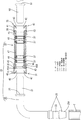
本発明の一実施形態を図1ないし図4によって説明する。
図1に示す60は金属製のパイプであって例えば、燃料タンク(図示せず)に対して装着されるとともに、先端寄りの位置には抜止めフランジ61が全周に亘って形成されている。一方、Tはゴム製の燃料チューブ(以下、単にチューブとする)であって、このチューブTとパイプ60との間が連結管10によって繋がれるようになっている。
An embodiment of the present invention will be described with reference to FIGS.
1 is a
連結管10は小径管20と大径管30とから分割構成されている。小径管20は金属製のパイプをL字状に折り曲げて形成されるとともに、その一端(図1における下端側)はチューブ嵌合部23とされ、外周面に環状をなす抜止め突条25が軸方向に2個形成されており、そこにチューブTが被せ付けられるようになっている。また、この抜止め突条25のうち下側の抜止め突条25の先端には下方に先細りするテーパ25Aが設けられているが、これは小径管20に対するチューブTの組付け動作を円滑に行うための誘いである。
The connecting
一方、他端(図1における右端部)はジョイント部21とされ、次に述べる大径管30の第1接続部31に対して内挿されるようになっている。ジョイント部21の先端寄りの位置には抜止めフランジ22が全周に亘って形成されている。 この抜止めフランジ22は後述する大径管30に設けられるロック部材40に対して係止して同小径管20を前記大径管30に対して抜止めするよう機能する。
On the other hand, the other end (the right end portion in FIG. 1) is a
また、抜止めフランジ22の小径管20本体からの突出高さと抜止め突条25の突出高さはほぼ等しくなっており、その径サイズは大径管30の内径のサイズより小さい設定とされている。
加えて、小径管20の外径寸法とパイプ60の外径寸法とは同じ寸法設定とされ更に、ジョイント部21の抜止めフランジ22の寸法設定(先端からの配置位置、幅、外周からの突出高さ)はパイプ60の抜止めフランジ61の各部位の寸法設定と同じ寸法設定とされている。
Further, the protruding height of the
In addition, the outer diameter dimension of the
ところで、この小径管20の成形を行う場合には、まず一様な径サイズの母材(母管)を用意しておき、その母材を徐々に絞り込んでゆくことで凹凸部分、すなわち抜止めフランジ22或いは抜止め突条25が成形されるされるようになっている。
By the way, when the
次に、大径管30は軸線が直線状をなす金属製の管よりなり、その左右両端部がそれぞれ小径管20或いはパイプ60に対する接続部31、35とされている。図1に示す左側の端部は第1接続部31であって、そこには小径管20のジョイント部21が内挿される。一方、右側の端部は第2接続部35であって、そこにはパイプ60の先端部分が内挿されるようになっている。この大径管30の接続部31、35は次述するシールに関する構造、抜止めに関する構造がいずれも同一構造とされており、大径管30は左右対称となっている。このような構成とすることで、大径管30を正逆反転させても、小径管20並びにパイプ60の接続が出来るようになっている。以下、大径管30の左半分について説明し、右半分については説明を省略する。
Next, the large-
大径管30の第1接続部31の内周側には一対のシールリング(本発明のシール部材に相当する)37がスペーサ47、48並びにブッシュ45によって位置決めされた状態で装着されている。このシールリング37は、ジョイント部21が第1接続部31に嵌合された時には、ジョイント部21の外周面と第1接続部31の内周面に密着することで、両間をシールするようになっている。また、大径管30の周壁には、図4に示すように次述するロック部材40を装着するためのロック孔36が周方向に3個形成されているが、このロック孔36はブッシュ45の抜止めも兼用している。ブッシュ45はその端部に径方向外側に張り出す3本の弾性片45Aを設けており、装着状態においては同弾性片45Aが前記ロック孔36に係止するようになっている。そして、弾性片45Aが形成された側の端部であって、その内周側には前方(小径管20との嵌合面側)に向かって間口が広くなるように傾斜する傾斜部45Bが設けられている。この傾斜部45Bは第1接続部31内にジョイント部21を円滑に嵌め込むための誘いである。
A pair of seal rings (corresponding to a seal member of the present invention) 37 are mounted on the inner peripheral side of the
ロック部材40は金属製のばね材よりなるとともに、図4に示すように割溝が軸線方向に入った円筒状をなす本体部41を設けてなる。この本体部41は大径管30の外周に装着可能な大きさに形成されるとともに、本体部41の周壁の後端寄りの位置(図4における奥側の端部)であって、前記ロック孔36と対向する各位置には内向きに(ロック孔36側に)屈曲形成された係止片43が設けられている。この係止片43は弾性変位可能とされ、ロック部材40が図1に示す組み付け位置(第1接続部31の外周に外嵌されその前端同士がほぼ揃った位置)に装着されるとロック孔36の孔壁に対して係止してロック部材40を抜止め状態に保持するようになっている。
The
また、本体部の開口縁(図4における手前側)には内向き屈曲する弾性抜止め片(本発明の弾性ロック爪に相当する)42が周方向に3個等間隔に設けられている。この弾性抜止め片42はロック部材40が組み付け位置に装着されたときには、そのほぼ全体が第1接続部31の内部空間に進入した状態となる。この弾性抜止め片42は第1接続部31内に挿入される小径管20の抜止めフランジ22に係止可能とされ同小径管20を大径管30に抜止め状態に保持するよう機能する。
In addition, three elastic retaining pieces (corresponding to the elastic lock claws of the present invention) 42 that are bent inward are provided at equal intervals in the circumferential direction on the opening edge (front side in FIG. 4) of the main body. When the
また、ロック部材40の後端部はその全周に亘って径方向外側に斜めに折り曲げられているが、これは大径管30に対するロック部材40の組み付けを円滑に行うための誘導斜部44である。尚、第2接続部35にも第1接続部31に装着されたロック部材40と同型のロック部材40が装着されているが、これはパイプ60を抜止め状態に保持するためのものである。
Further, the rear end portion of the
次に、本実施形態の作用効果について説明する。
チューブTとパイプ20を繋ぐには、まずチューブTの前端を小径管20のチューブ嵌合部23に宛って、その状態からチューブTを小径管20に向けて押し込む。これにより、チューブTはチューブ嵌合部23の先端に設けられるテーパ25Aによって径方向外側に押し拡げられつつ、チューブ嵌合部23の外周に被されてゆく。やがて、チューブTの上端が上側の抜止め突条25の上端まで達し、チューブTの組み付けが完了する。この取り付け状態においてチューブTは、図2に示すようにチューブ嵌合部23の外周に密着した状態にあって、チューブ嵌合部23の備える抜止め突条25によって抜止め状態に保持される。
Next, the effect of this embodiment is demonstrated.
In order to connect the tube T and the
次に、大径管30に対してパイプ60並びに小径管20を接続する。それには、小径管20のジョイント部21或いはパイプ60の先端を大径管30の第1・或いは第2接続部31、35に宛って、その状態から小径管20或いはパイプ60を大径管30に向かって押し込んでゆく。すると、パイプ60或いは小径管20が大径管30の内部に進入する過程で、抜止めフランジ22、61がロック部材40の弾性抜止め片42に当接し、弾性抜止め片42をロック解除方向に弾性変位させる。その後、小径管20並びにパイプ60が図3に示す組み付け位置に至ると、抜止めフランジ22、61が弾性抜止め片42を通過する。これにより、弾性抜止め片42が復帰して小径管20並びにパイプ60の抜止めフランジ22、61に係止する。以上より、チューブT並びにパイプ60が小径管20、大径管30を介して接続されることとなる。
Next, the
本実施形態によれば、小径管20並びに大径管30は金属製であるからこれらの部品を樹脂製とする場合に比べてチューブTとパイプ60を接続する部分の強度が高くなる。また、これら両管20、30が金属製である場合にはその加工性が問題となるが、この点に関しても小径管20と大径管30を分割することで良好な加工性が維持されるようになっている。というもの、仮に小径管20と大径管30が一体に成形されていると、母材は大径管30に合わせて選択されるため、小径管20を成形する際の絞りの深さが深くなる。しかもこの小径管20には抜止め突条25が形成されているため絞りが深い上に複雑な加工を行う必要があり加工性が悪くなる。しかし、径の太い部分(大径管30)と細い部分(小径管20)が分割されていれば、各管20、30毎にそれぞれの管の径サイズに対応した母材を選択することが可能となる。従って、小径管20においてはその分深い絞り加工を行う必要がなくなり、小径管20の外周に抜止め突条25が形成されているにも拘わらず、良好な加工性が維持される。
According to this embodiment, since the small-
加えて、大径管30に対する小径管20或いはパイプ60の装着動作に伴って、ロック部材40が小径管20或いはパイプ60に対して係止する。従って、小径管20並びにパイプ60の組付け動作をワンタッチで行うことが出来る。
そして、大径管30は左右対称形状をなしており、正逆反転された状態であっても小径管20或いはパイプ60の接続作業を行うことが出来るようになっている。従って、誤組付けの心配がなく組み付け作業性にも優れる。
In addition, the
The large-
<他の実施形態>
本発明は上記記述及び図面によって説明した実施形態に限定されるものではなく、例えば次のような実施形態も本発明の技術的範囲に含まれ、さらに、下記以外にも要旨を逸脱しない範囲内で種々変更して実施することができる。
<Other embodiments>
The present invention is not limited to the embodiments described with reference to the above description and drawings. For example, the following embodiments are also included in the technical scope of the present invention, and further, within the scope not departing from the gist of the invention other than the following. Various modifications can be made.
(1)本実施形態では、小径管20を1種類しか設けていないが、チューブ嵌合部23の形状のみ異なる複数個の小径管20を用意しておけば、パイプに対して複数種類のチューブを接続することが可能となる。
(1) In this embodiment, only one type of
(2)本実施形態では、連結管10をチューブTとパイプ60との接続に使用したが、チューブT同士の接続に使用してもよい。
(2) In the present embodiment, the connecting
(3)本実施形態では、大径管30を一様な径のストレート管により構成したが、小径管20を内周側に嵌め合わせることが可能なものであればよく、例えば小径管20が接続される端部を大径としておき、その他の部分を小径管20と同径とするものであってもよい。
(3) In the present embodiment, the large-
T…チューブ
20…小径管
30…大径管
31…第1接続部
35…第2接続部
60…パイプ(他の配管)
T ...
Claims (5)
筒状をなすとともに、その一端部には径方向外側に張り出し同端部に被せ付けられる前記チューブを装着状態に保持する複数個の抜止め突条を有する金属製の小径管と、
一端側が前記小径管が接続される第1接続部とされ他端側が前記他の配管が接続される第2接続部とされた金属製の大径管とを備えてなることを特徴とする配管接続構造。 A pipe connection structure in which a flexible tube is put on the outer periphery on one end side and another pipe is connected on the other end side,
A metal small-diameter pipe having a plurality of retaining protrusions that form a tube and that has one end portion extending outward in the radial direction and holding the tube attached to the same end portion in a mounted state;
A pipe having a metal large-diameter pipe having one end side as a first connection portion to which the small-diameter pipe is connected and the other end side as a second connection portion to which the other pipe is connected. Connection structure.
Priority Applications (1)
| Application Number | Priority Date | Filing Date | Title |
|---|---|---|---|
| JP2004114291A JP2005299749A (en) | 2004-04-08 | 2004-04-08 | Pipe connection structure |
Applications Claiming Priority (1)
| Application Number | Priority Date | Filing Date | Title |
|---|---|---|---|
| JP2004114291A JP2005299749A (en) | 2004-04-08 | 2004-04-08 | Pipe connection structure |
Publications (1)
| Publication Number | Publication Date |
|---|---|
| JP2005299749A true JP2005299749A (en) | 2005-10-27 |
Family
ID=35331530
Family Applications (1)
| Application Number | Title | Priority Date | Filing Date |
|---|---|---|---|
| JP2004114291A Pending JP2005299749A (en) | 2004-04-08 | 2004-04-08 | Pipe connection structure |
Country Status (1)
| Country | Link |
|---|---|
| JP (1) | JP2005299749A (en) |
Cited By (1)
| Publication number | Priority date | Publication date | Assignee | Title |
|---|---|---|---|---|
| JP2017187073A (en) * | 2016-04-01 | 2017-10-12 | ゼンシン株式会社 | Fastener for pipe coupling |
-
2004
- 2004-04-08 JP JP2004114291A patent/JP2005299749A/en active Pending
Cited By (1)
| Publication number | Priority date | Publication date | Assignee | Title |
|---|---|---|---|---|
| JP2017187073A (en) * | 2016-04-01 | 2017-10-12 | ゼンシン株式会社 | Fastener for pipe coupling |
Similar Documents
| Publication | Publication Date | Title |
|---|---|---|
| US8056937B2 (en) | Tube couplings | |
| US9777875B2 (en) | Clam shell push-to-connect assembly | |
| US7328922B2 (en) | Quick connector | |
| US7837234B2 (en) | Pipe joint unit and method of manufacturing the same | |
| MXPA03006136A (en) | Pipe joint. | |
| JPH02266190A (en) | Connector device for fine diametral piping connection | |
| US11098833B2 (en) | Quick connector | |
| WO2016132745A1 (en) | Pipe joint | |
| US20050221679A1 (en) | Quick connector | |
| JP2005299749A (en) | Pipe connection structure | |
| JP2006300127A (en) | Fastener | |
| JP3386406B2 (en) | Pipe fittings | |
| JP2015078749A (en) | Pipe joint | |
| JP4699286B2 (en) | Corrugated pipe insertion joint and stopper | |
| JP2014095434A (en) | Pipe joint with flange | |
| JP2007064367A (en) | Pipe coupling structure | |
| JP6594160B2 (en) | Sealing material and pipe fittings | |
| JP6490910B2 (en) | Removal jig | |
| CN213018257U (en) | Fast inserting structure and pipeline structure with same | |
| CN218119006U (en) | Pipeline connection structure, engine pipeline and vehicle | |
| CN221145685U (en) | Detachable quick connector | |
| CN209743844U (en) | pipeline connection structure, engine pipeline and vehicle | |
| JP4979652B2 (en) | Method of connecting rubber ring joints of ribbed pipes, ribbed pipes and sewer pipes | |
| JP6813183B2 (en) | Assembling method of pipe fittings and pipe fittings | |
| JP2007032813A (en) | Pipe connection structure |
Legal Events
| Date | Code | Title | Description |
|---|---|---|---|
| RD04 | Notification of resignation of power of attorney |
Free format text: JAPANESE INTERMEDIATE CODE: A7424 Effective date: 20060531 |