JP2005299748A - Hinge and image forming apparatus using the same - Google Patents
Hinge and image forming apparatus using the same Download PDFInfo
- Publication number
- JP2005299748A JP2005299748A JP2004114252A JP2004114252A JP2005299748A JP 2005299748 A JP2005299748 A JP 2005299748A JP 2004114252 A JP2004114252 A JP 2004114252A JP 2004114252 A JP2004114252 A JP 2004114252A JP 2005299748 A JP2005299748 A JP 2005299748A
- Authority
- JP
- Japan
- Prior art keywords
- case
- rotating body
- hinge
- scanner unit
- side wall
- Prior art date
- Legal status (The legal status is an assumption and is not a legal conclusion. Google has not performed a legal analysis and makes no representation as to the accuracy of the status listed.)
- Granted
Links
- 239000002184 metal Substances 0.000 description 13
- 230000006835 compression Effects 0.000 description 10
- 238000007906 compression Methods 0.000 description 10
- 230000002093 peripheral effect Effects 0.000 description 3
- 238000013459 approach Methods 0.000 description 2
- 238000010586 diagram Methods 0.000 description 2
- 230000005484 gravity Effects 0.000 description 2
- 239000011347 resin Substances 0.000 description 2
- 229920005989 resin Polymers 0.000 description 2
- 238000007599 discharging Methods 0.000 description 1
- 230000000694 effects Effects 0.000 description 1
- 230000003287 optical effect Effects 0.000 description 1
Images


Landscapes
- Pivots And Pivotal Connections (AREA)
- Facsimiles In General (AREA)
Abstract
【課題】 揺動に対する摩擦による制動力が大きいヒンジ、及びそれを用いた画像形成装置を提供する。
【解決手段】本体または揺動体の一方に取り付けられる筒状のケースと、前記本体または前記揺動体の他方に取り付けられ、前記ケースの互いに向き合う側壁に回転自在に支持される回転体と、前記回転体に形成され前記側壁と圧接し前記側壁を前記回転体の回転軸方向に押圧する圧接部と、前記回転体に形成されるカム部と、前記ケースに往復移動自在に収容され前記カム部と摺接する斜面を有するくさび体と、前記ケースに収容され前記くさび体を前記回転体側に付勢する弾性部材と、を備えることを特徴とするヒンジ。
【選択図】 図1PROBLEM TO BE SOLVED: To provide a hinge having a large braking force due to friction against swinging, and an image forming apparatus using the hinge.
A cylindrical case attached to one of a main body or an oscillating body, a rotating body attached to the other side of the main body or the oscillating body, and rotatably supported on mutually facing side walls of the case, and the rotation A pressure contact portion formed on the body and pressed against the side wall to press the side wall in the direction of the rotation axis of the rotating body; a cam portion formed on the rotating body; A hinge comprising: a wedge body having an inclined surface in sliding contact; and an elastic member housed in the case and biasing the wedge body toward the rotating body.
[Selection] Figure 1
Description
本発明はヒンジ及びそれを用いた画像形成装置に関する。 The present invention relates to a hinge and an image forming apparatus using the hinge.
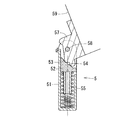
画像形成装置として、プリンタとイメージスキャナとを一体化した所謂複合機が知られている。こうした複合機の中には、スキャナ部を揺動体とし、印刷部を本体として両者をヒンジで搖動自在に連結しているものが知られている。しかしながら、スキャナ部と印刷部とを搖動自在に連結した複合機の場合、スキャナ部が自重により閉じると、衝撃による故障が発生する場合がある。 As an image forming apparatus, a so-called multifunction machine in which a printer and an image scanner are integrated is known. Among such multi-function machines, there is known a printer in which a scanner unit is a rocking body, a printing unit is a main body, and both are slidably connected by a hinge. However, in the case of a multifunction machine in which the scanner unit and the printing unit are slidably connected, a failure due to an impact may occur when the scanner unit closes due to its own weight.
特許文献1には、図8に示すように、制動機構を備えるヒンジ5によってスキャナ部59と図示しない印刷部とが連結された画像形成装置が開示されている。印刷部に固定されるケース51は筒状に形成され、くさび体52を往復移動自在に収容している。くさび体52は回転体57のカム部53に圧接する斜面54を有し、ケース51に収容された圧縮コイルばね55でカム部53の金属シャフト58に接近する方向に押されている。ケース51にはスキャナ部59に固定される回転体57が金属シャフト58で搖動自在に連結されている。くさび体52が圧縮コイルばね55で押されることにより、くさび体52の斜面54がカム部53を押すため、金属シャフト58を中心として紙面上で反時計回りに回転させるトルクが回転体57に作用する。このトルクはスキャナ部59を開く力として作用するため、閉じるときにはスキャナ部59が自重により閉じるのを防止する。
しかし、特許文献1に記載された画像形成装置によると、金属シャフト58が挿入される軸穴が、温度変化により熱変形したり、カム部53がくさび体52に常時圧接することにより金属シャフト58から受ける力で変形したり、繰り返し揺動操作を行うことにより金属シャフト58との間に発生する摩擦により変形する。金属シャフト58が挿入される軸穴が広がると、回転の制動力が弱まるという問題がある。また、繰り返し揺動を行うことによりくさび体52とカム部53の圧接部が磨耗し、回転の制動力が弱まるという問題がある。さらに、スキャナ部59の重量が増加する場合、揺動体の重量に対して十分な制動力を発生させるためには圧縮コイルばね55のばね定数を上げるとともにヒンジ5の各部の強度を上げなければならないという問題がある。
However, according to the image forming apparatus described in
本発明は、このような問題を解決するために創作されたものであって、揺動に対する摩擦による制動力が大きいヒンジ、及びそれを用いた画像形成装置を提供することを目的とする。 The present invention has been created to solve such problems, and an object of the present invention is to provide a hinge having a large braking force due to friction against swinging, and an image forming apparatus using the hinge.
上記目的を達成するためのヒンジは、本体または揺動体の一方に取り付けられる筒状のケースと、前記本体または前記揺動体の他方に取り付けられ、前記ケースの互いに向き合う側壁に回転自在に支持される回転体と、前記回転体に形成され前記側壁と圧接し前記側壁を前記回転体の回転軸方向に押圧する圧接部と、前記回転体に形成されるカム部と、前記ケースに往復移動自在に収容され前記カム部と摺接する斜面を有するくさび体と、前記ケースに収容され前記くさび体を前記回転体側に付勢する弾性部材と、を備える。ケースの側壁と圧接する圧接部を回転体に形成することにより、揺動体の揺動時に、回転体の圧接部とケースの側壁との間の摩擦力による制動力を発生させることができる。また、圧接部が回転体の回転軸線と平行な方向にケースの側壁を押圧する構成では、摩擦力を発生させる抗力は回転体の回転軸方向に作用するため、回転体の回転軸及び軸穴がその抗力によって変形することを防止できる。 A hinge for achieving the above object is attached to one of a main body or an oscillating body and a cylindrical case attached to the other of the main body or the oscillating body, and is rotatably supported on opposite side walls of the case. A rotary body, a pressure contact portion formed on the rotary body and pressed against the side wall to press the side wall in a direction of a rotation axis of the rotary body, a cam portion formed on the rotary body, and a reciprocating movement to the case A wedge body having an inclined surface that is accommodated and slidably contacts the cam portion; and an elastic member that is accommodated in the case and biases the wedge body toward the rotating body. By forming the pressure contact portion in pressure contact with the side wall of the case on the rotating body, it is possible to generate a braking force due to a frictional force between the pressure contact portion of the rotating body and the side wall of the case when the swinging body swings. Further, in the configuration in which the press contact portion presses the side wall of the case in a direction parallel to the rotation axis of the rotating body, the drag force that generates a frictional force acts in the direction of the rotating shaft of the rotating body. Can be prevented from being deformed by the drag.
前記ケースの前記側壁は、前記揺動体が全閉姿勢と全開姿勢の中間姿勢になる期間中にのみ前記回転体の前記圧接部に圧接することが望ましい。全閉姿勢及び全開姿勢のときには圧接部がケースの側壁に圧接しない構成では、圧接部がケースの側壁を押圧する期間を短くすることができる。その結果、ケースの側壁の塑性変形を抑制することができる。 It is desirable that the side wall of the case is in pressure contact with the pressure contact portion of the rotating body only during a period when the swinging body is in an intermediate position between a fully closed position and a fully open position. In the configuration in which the pressure contact portion does not press the side wall of the case in the fully closed posture and the fully open posture, the period during which the pressure contact portion presses the side wall of the case can be shortened. As a result, plastic deformation of the side wall of the case can be suppressed.
上記目的を達成するための画像形成装置は、印刷部と、前記印刷部の上部に載置されるスキャナ部と、前記印刷部に前記スキャナ部を搖動自在に連結する前記ヒンジとを備える。印刷部とスキャナ部を連結するヒンジを前記ヒンジで構成することにより、スキャナ部の自重による閉動作に対する制動力を摩擦力によって増大させることができる。 In order to achieve the above object, an image forming apparatus includes a printing unit, a scanner unit placed on the printing unit, and the hinge that slidably connects the scanner unit to the printing unit. By configuring the hinge connecting the printing unit and the scanner unit with the hinge, the braking force against the closing operation due to the weight of the scanner unit can be increased by the frictional force.
以下、本発明を実施するための最良の形態を実施例に基づいて説明する。
図2は、本発明の一実施例に係るヒンジ1を用いた画像形成装置としての複合機4を示す模式図である。複合機4は、請求項に記載の揺動体としてのスキャナ部30と請求項に記載の本体としての印刷部20とを備えている。スキャナ部30は画像の読み取り機能を有する。印刷部20は画像の印刷機能を有する。また複合機4は、スキャナ部30で読み取った画像を印刷部20で印刷することができるため、全体として複写機能を有する。
Hereinafter, the best mode for carrying out the present invention will be described based on examples.
FIG. 2 is a schematic diagram showing a
スキャナ部30は、ヒンジ1の金属シャフト15を中心に揺動する。スキャナハウジング3は、スキャナ部30のハウジングである。スキャナハウジング3は樹脂等で箱形に形成されている。スキャナ部30は、原稿台39を有し、所謂フラットベッド型のスキャナを構成している。スキャナ部30には、原稿台39の盤面を覆う原稿台カバー32が搖動可能に接続されている。スキャナ部30は、光源34、ミラー35、レンズ36、リニアイメージセンサ37、キャリッジ38などを備えている。キャリッジ38は、原稿台39の盤面と平行な方向に往復移動可能に設けられ、光源34、ミラー35及びレンズ36からなる光学系とリニアイメージセンサ37とをA、B方向に運搬する。破線で示すように、ミラー35及びレンズ36は光源34により照射された被写体Mの反射光像をリニアイメージセンサ37に結像する。
The
プリンタハウジング2は、印刷部20のハウジングである。プリンタハウジング2は樹脂等で箱形に形成されている。印刷部20は、スキャナ部30を搖動可能に支持している。全閉状態のスキャナ部30は印刷部20の上部に載置され、スキャナ部30はプリンタハウジング2によって支持される。尚、本実施例では、スキャナ部30の底部が印刷部20の上部に載置されている状態を全閉状態といい、スキャナ部30の底部が印刷部20の上部から最も離れた状態を全開状態というものとする。印刷部20のキャリッジ22は、複数のカードリッジ23及び記録ヘッド24をC、D方向に運搬する。各カートリッジ23に収容されているインクは記録ヘッド24により印刷用紙Nに噴射される。印刷部20の送紙機構26は、印刷部20の図示しない給紙口に供給された印刷用紙Nを図示しないプラテン上に搬送し印刷部20の図示しない排紙口から排出する。
制御部40は、パーソナルコンピュータ等の外部システム又はスキャナ部30から入力される、画像データ又は印刷データに基づいて送紙機構26及び記録ヘッド24の作動を制御する。
The
The
図3は、本発明の一実施例に係るヒンジ1の外観を示す断面図である。本実施例ではヒンジ1のケース14を印刷部20に図示しないねじで取り付け、回転体11をスキャナ部30に図示しないねじで取り付けている。尚、ケース14をスキャナ部30に取り付け、回転体11を印刷部20に取り付けてもよい。
図4は、ヒンジ1の分解斜視図である。ヒンジ1は、回転体11と、くさび体12と、請求項に記載の弾性部材としての圧縮コイルばね13と、ケース14と、金属シャフト15と、金属シャフト15の抜けを防止するリング部材16とを備える。
FIG. 3 is a cross-sectional view showing the appearance of the
FIG. 4 is an exploded perspective view of the
回転体11は、両端部に形成されたねじ穴116、117にねじ込まれる図示しないねじによってスキャナ部30に固定される。回転体11は、軸穴114に挿入される金属シャフト15が軸穴144及び軸穴145に挿入されることによって、ケース14に回転自在に支持される。軸穴114はボス部118に形成されている。ボス部118の端面がケース14の内壁面に当接することにより、回転体11は金属シャフト15の中心軸線方向に位置決めされる。回転体11のケース14に収容される部位の側面の一部が請求項に記載の圧接部に相当する。回転体11のケース14に収容される部位の外周面の一部が請求項に記載のカム部に相当する。尚、本実施例において回転体11の側面とは、回転体11の外壁面のうち回転体11の回転軸線に対して垂直な部位をいうものとする。また本実施例において回転体11の外周面とは、回転体11の外壁面のうち回転体11の回転軸線に平行な線分の平行移動軌跡に相当する部位をいいうものとする。以下、回転体11のケース14に収容される部位の側面を圧接部113といい、回転体11のケース14に収容される部位の外周面をカム部112というものとする。
The rotating
ケース14は、開口部143を有する有低筒状に形成されている。ケース14には圧縮コイルばね13とくさび体12が収容される。向かい合う一対の側壁141及び142の開口部143側の端部には金属シャフト15が回転自在に挿入される軸孔144、145が形成されている。ケース14は、プリンタハウジング2に形成された図示しない凹部に挿入され、ねじ穴148にねじ込まれる図示しないねじによって印刷部20に固定される。
くさび体12は、ケース14に往復移動可能に圧入される。くさび体12は、回転体11のカム部112と圧接する斜面121を有する。くさび体12がケース14内を往復移動する時、くさび体12とケース14の内壁面との間で摩擦力が生じる。この摩擦力はヒンジ1の揺動に対する制動力として作用する。
The
The
図5は、本発明の一実施例に係るケース14を示す斜視図である。ケース14の側壁141及び側壁142の互いに向かい合う内壁面にそれぞれ段部146及び突部147が形成されている。段部146は、回転体11の回転軸線と平行な線分の平行移動軌跡に相当する形状である。段部146は、回転体11が所定の姿勢にあるとき図6(B)に示すように回転体11の角部115に圧接する。段部146と角部115が圧接した状態では、段部146と角部115との間にヒンジ1の揺動に対する制動力となる摩擦力が発生する。2つの突部147は、それぞれ段部146と軸穴144の間に形成されている。突部147の外縁は面取りされている。
FIG. 5 is a perspective view showing a
次に、ヒンジ1の作動について説明する。
図1(A)は、スキャナ部30が全開姿勢のときのケース14と圧接部113の位置関係を示している。図1(B)は、スキャナ部30が全閉姿勢でもなく全開姿勢でもない中間姿勢のときのケース14と圧接部113の位置関係を示している。図1(C)は、スキャナ部30が全閉姿勢のときのケース14と圧接部113の位置関係を示している。スキャナ部30が全開姿勢のときと全閉姿勢のときは、回転体11の圧接部113は側壁141にも側壁142にも圧接しない。回転体11の圧接部113は、スキャナ部30が全開姿勢でもなく全閉姿勢でもない中間姿勢になる期間中に、図6(B)に示すように側壁142の突部147と側壁141の突部147に圧接する。圧接部113が側壁142の突部147と側壁141の突部147とに圧接しながら回転体11が回転すると発生する摩擦力は、ヒンジ1が揺動する作動に対する制動力になる。
Next, the operation of the
FIG. 1A shows the positional relationship between the
図7(A)は、スキャナ部30が全閉姿勢のときのヒンジ1を示す断面図であり、図7(B)は、全開姿勢のときのヒンジ1を示す断面図である。図7(A)に示す全閉姿勢から図7(B)に示す全開姿勢になる方向にスキャナ部30を揺動させると(すなわちスキャナ部30を開くと)、圧縮コイルばね13は伸張する。スキャナ部30の姿勢が全閉姿勢に近いときは、圧縮コイルばね13がくさび体12を押し上げることによってスキャナ部30を開方向に回転させる力も、スキャナ部30に作用する重力の閉方向の分力も大きい。ここでいう閉方向とはスキャナ部30が全閉姿勢に近付く回転方向である。一方、スキャナ部30の姿勢が全開姿勢に近いときは、圧縮コイルばね13がくさび体12を押し上げることによってスキャナ部30を開方向に回転させる力も、スキャナ部30に作用する重力の閉方向の分力も小さい。ここでいう開方向とはスキャナ部30が全開姿勢に近付く回転方向である。すなわち、スキャナ部30が閉じる作動に対する圧縮コイルばね13による制動力はスキャナ部30が自重によって閉じようとする力に応じて変化する。
FIG. 7A is a cross-sectional view showing the
以上説明した本発明の一実施例によれば、ケース14の側壁141及び142にそれぞれ形成された突部147に回転体11の圧接部113が圧接すると摩擦力が発生し、スキャナ部30の揺動に対する制動力が増大する。また、突部147に圧接する回転体11の圧接部113は、回転体11の回転軸線と垂直な面で構成されているため、突部147と圧接部113の間の摩擦力を発生させる効力は、回転体11の回転軸線と平行な方向に作用する。したがって、回転体11を回転自在に支持する軸穴144及び145の変形を抑制しつつ、スキャナ部30の揺動作動に対する摩擦による制動力を増大させることができる。
また、圧接部113は、スキャナ部30が全閉姿勢と全開姿勢になる状態ではケース14の側壁141、142に圧接しない。したがって、ケース14の塑性変形により圧接部113と側壁141、142との間の摩擦力が低下することを抑制できる。
According to the embodiment of the present invention described above, a frictional force is generated when the
Further, the
1 ヒンジ、2 プリンタハウジング、3 スキャナハウジング、11 回転体、12 くさび体、13 圧縮コイルばね(弾性部材)、14 ケース、20 印刷部(本体)、30 スキャナ部(揺動体)、112 カム部、113 第一当接部(圧接部)、121 斜面、147 突部
DESCRIPTION OF
Claims (3)
前記本体または前記揺動体の他方に取り付けられ、前記ケースの互いに向き合う側壁に回転自在に支持される回転体と、
前記回転体に形成され前記側壁と圧接し前記側壁を前記回転体の回転軸方向に押圧する圧接部と、
前記回転体に形成されるカム部と、
前記ケースに往復移動自在に収容され前記カム部と摺接する斜面を有するくさび体と、
前記ケースに収容され前記くさび体を前記回転体側に付勢する弾性部材と、
を備えることを特徴とするヒンジ。 A cylindrical case attached to one of the main body or the rocking body;
A rotating body attached to the other of the main body or the rocking body and rotatably supported by mutually facing side walls of the case;
A pressure-contact portion that is formed on the rotating body and presses against the side wall to press the side wall in the direction of the rotation axis of the rotating body;
A cam portion formed on the rotating body;
A wedge body that is accommodated in the case so as to be reciprocally movable and has a slope that is in sliding contact with the cam portion;
An elastic member housed in the case and biasing the wedge body toward the rotating body;
A hinge comprising:
前記印刷部の上部に載置されるスキャナ部と、
前記印刷部に前記スキャナ部を搖動自在に連結する請求項1又は2に記載のヒンジと、
を備えることを特徴とする画像形成装置。
A printing section;
A scanner unit placed on top of the printing unit;
The hinge according to claim 1 or 2, wherein the scanner unit is slidably coupled to the printing unit.
An image forming apparatus comprising:
Priority Applications (1)
| Application Number | Priority Date | Filing Date | Title |
|---|---|---|---|
| JP2004114252A JP4424043B2 (en) | 2004-04-08 | 2004-04-08 | Hinge and image forming apparatus using the same |
Applications Claiming Priority (1)
| Application Number | Priority Date | Filing Date | Title |
|---|---|---|---|
| JP2004114252A JP4424043B2 (en) | 2004-04-08 | 2004-04-08 | Hinge and image forming apparatus using the same |
Publications (2)
| Publication Number | Publication Date |
|---|---|
| JP2005299748A true JP2005299748A (en) | 2005-10-27 |
| JP4424043B2 JP4424043B2 (en) | 2010-03-03 |
Family
ID=35331529
Family Applications (1)
| Application Number | Title | Priority Date | Filing Date |
|---|---|---|---|
| JP2004114252A Expired - Fee Related JP4424043B2 (en) | 2004-04-08 | 2004-04-08 | Hinge and image forming apparatus using the same |
Country Status (1)
| Country | Link |
|---|---|
| JP (1) | JP4424043B2 (en) |
Cited By (3)
| Publication number | Priority date | Publication date | Assignee | Title |
|---|---|---|---|---|
| JP2009071804A (en) * | 2007-08-21 | 2009-04-02 | Kato Electrical Mach Co Ltd | Document crimping plate opening and closing device and office equipment equipped with document crimping plate |
| JP2010091079A (en) * | 2008-10-10 | 2010-04-22 | Yano Seisakusho:Kk | Hinge mechanism |
| JP2010271627A (en) * | 2009-05-25 | 2010-12-02 | Shimonishi Giken Kogyo Kk | Opening/closing device for document-pressing plate |
-
2004
- 2004-04-08 JP JP2004114252A patent/JP4424043B2/en not_active Expired - Fee Related
Cited By (3)
| Publication number | Priority date | Publication date | Assignee | Title |
|---|---|---|---|---|
| JP2009071804A (en) * | 2007-08-21 | 2009-04-02 | Kato Electrical Mach Co Ltd | Document crimping plate opening and closing device and office equipment equipped with document crimping plate |
| JP2010091079A (en) * | 2008-10-10 | 2010-04-22 | Yano Seisakusho:Kk | Hinge mechanism |
| JP2010271627A (en) * | 2009-05-25 | 2010-12-02 | Shimonishi Giken Kogyo Kk | Opening/closing device for document-pressing plate |
Also Published As
| Publication number | Publication date |
|---|---|
| JP4424043B2 (en) | 2010-03-03 |
Similar Documents
| Publication | Publication Date | Title |
|---|---|---|
| JP4645446B2 (en) | Image forming apparatus | |
| JP4569687B2 (en) | Rotating device | |
| JP2011203574A (en) | Multifunctional peripheral | |
| JP6904771B2 (en) | Thermal printers and portable terminals | |
| JP7749967B2 (en) | printer | |
| JP4724621B2 (en) | Image reading and recording device | |
| JP4424043B2 (en) | Hinge and image forming apparatus using the same | |
| US7069622B2 (en) | Hinge and image input/output apparatus therewith | |
| CN107379779B (en) | Thermal printer and portable terminal | |
| JP4984468B2 (en) | Electronics | |
| JP3841211B2 (en) | Hinge and image input / output device using the same | |
| JP2003129739A (en) | Hinge and image input / output device using the same | |
| JP2008100381A (en) | Thermal printer | |
| JP6642885B2 (en) | Hinge | |
| JP6358149B2 (en) | Panel device and image recording device | |
| JP5471332B2 (en) | Image recording device | |
| JP6238612B2 (en) | Printing device | |
| JP4375368B2 (en) | Paper transport mechanism and image forming apparatus having the same | |
| US10668712B2 (en) | Printing device having engagement portion for suppressing disengagement of bearing from holder | |
| JP3944642B2 (en) | Image input / output device | |
| CN223702074U (en) | Printer with a printer body | |
| JP4341352B2 (en) | Hinge and image input / output device having the same | |
| JP7334488B2 (en) | printer | |
| JP2003054070A (en) | Opening / closing member support mechanism, tray, and recording device | |
| JP4636385B2 (en) | Image forming apparatus |
Legal Events
| Date | Code | Title | Description |
|---|---|---|---|
| RD04 | Notification of resignation of power of attorney |
Free format text: JAPANESE INTERMEDIATE CODE: A7424 Effective date: 20060818 |
|
| RD04 | Notification of resignation of power of attorney |
Free format text: JAPANESE INTERMEDIATE CODE: A7424 Effective date: 20061222 |
|
| RD03 | Notification of appointment of power of attorney |
Free format text: JAPANESE INTERMEDIATE CODE: A7423 Effective date: 20061226 |
|
| A621 | Written request for application examination |
Free format text: JAPANESE INTERMEDIATE CODE: A621 Effective date: 20070403 |
|
| RD04 | Notification of resignation of power of attorney |
Free format text: JAPANESE INTERMEDIATE CODE: A7424 Effective date: 20070403 |
|
| A131 | Notification of reasons for refusal |
Free format text: JAPANESE INTERMEDIATE CODE: A131 Effective date: 20090623 |
|
| A977 | Report on retrieval |
Free format text: JAPANESE INTERMEDIATE CODE: A971007 Effective date: 20090625 |
|
| A521 | Request for written amendment filed |
Free format text: JAPANESE INTERMEDIATE CODE: A523 Effective date: 20090821 |
|
| TRDD | Decision of grant or rejection written | ||
| A01 | Written decision to grant a patent or to grant a registration (utility model) |
Free format text: JAPANESE INTERMEDIATE CODE: A01 Effective date: 20091117 |
|
| A01 | Written decision to grant a patent or to grant a registration (utility model) |
Free format text: JAPANESE INTERMEDIATE CODE: A01 |
|
| A61 | First payment of annual fees (during grant procedure) |
Free format text: JAPANESE INTERMEDIATE CODE: A61 Effective date: 20091130 |
|
| R150 | Certificate of patent or registration of utility model |
Ref document number: 4424043 Country of ref document: JP Free format text: JAPANESE INTERMEDIATE CODE: R150 Free format text: JAPANESE INTERMEDIATE CODE: R150 |
|
| FPAY | Renewal fee payment (event date is renewal date of database) |
Free format text: PAYMENT UNTIL: 20121218 Year of fee payment: 3 |
|
| FPAY | Renewal fee payment (event date is renewal date of database) |
Free format text: PAYMENT UNTIL: 20121218 Year of fee payment: 3 |
|
| FPAY | Renewal fee payment (event date is renewal date of database) |
Free format text: PAYMENT UNTIL: 20131218 Year of fee payment: 4 |
|
| S531 | Written request for registration of change of domicile |
Free format text: JAPANESE INTERMEDIATE CODE: R313531 |
|
| R350 | Written notification of registration of transfer |
Free format text: JAPANESE INTERMEDIATE CODE: R350 |
|
| LAPS | Cancellation because of no payment of annual fees |