JP4984468B2 - Electronics - Google Patents
Electronics Download PDFInfo
- Publication number
- JP4984468B2 JP4984468B2 JP2005277314A JP2005277314A JP4984468B2 JP 4984468 B2 JP4984468 B2 JP 4984468B2 JP 2005277314 A JP2005277314 A JP 2005277314A JP 2005277314 A JP2005277314 A JP 2005277314A JP 4984468 B2 JP4984468 B2 JP 4984468B2
- Authority
- JP
- Japan
- Prior art keywords
- display unit
- liquid crystal
- crystal display
- guide groove
- key
- Prior art date
- Legal status (The legal status is an assumption and is not a legal conclusion. Google has not performed a legal analysis and makes no representation as to the accuracy of the status listed.)
- Expired - Fee Related
Links
- 210000000078 claw Anatomy 0.000 claims description 42
- 239000013013 elastic material Substances 0.000 claims description 4
- 238000003825 pressing Methods 0.000 claims description 3
- 239000004973 liquid crystal related substance Substances 0.000 description 133
- 230000036544 posture Effects 0.000 description 45
- 230000001681 protective effect Effects 0.000 description 26
- 229920001971 elastomer Polymers 0.000 description 22
- 230000007246 mechanism Effects 0.000 description 22
- 230000006870 function Effects 0.000 description 7
- 230000005489 elastic deformation Effects 0.000 description 6
- 238000010586 diagram Methods 0.000 description 4
- 239000011521 glass Substances 0.000 description 4
- 238000004519 manufacturing process Methods 0.000 description 3
- 238000000034 method Methods 0.000 description 3
- 239000003921 oil Substances 0.000 description 3
- 230000008569 process Effects 0.000 description 3
- 230000000694 effects Effects 0.000 description 2
- 230000002093 peripheral effect Effects 0.000 description 2
- 239000011347 resin Substances 0.000 description 2
- 229920005989 resin Polymers 0.000 description 2
- 229920002379 silicone rubber Polymers 0.000 description 2
- 230000032258 transport Effects 0.000 description 2
- 230000001154 acute effect Effects 0.000 description 1
- 230000008859 change Effects 0.000 description 1
- 238000009792 diffusion process Methods 0.000 description 1
- 239000000428 dust Substances 0.000 description 1
- 239000002184 metal Substances 0.000 description 1
- 238000001454 recorded image Methods 0.000 description 1
- 238000003860 storage Methods 0.000 description 1
- 239000000758 substrate Substances 0.000 description 1
Images


Classifications
-
- B—PERFORMING OPERATIONS; TRANSPORTING
- B41—PRINTING; LINING MACHINES; TYPEWRITERS; STAMPS
- B41J—TYPEWRITERS; SELECTIVE PRINTING MECHANISMS, i.e. MECHANISMS PRINTING OTHERWISE THAN FROM A FORME; CORRECTION OF TYPOGRAPHICAL ERRORS
- B41J29/00—Details of, or accessories for, typewriters or selective printing mechanisms not otherwise provided for
- B41J29/02—Framework
-
- B—PERFORMING OPERATIONS; TRANSPORTING
- B41—PRINTING; LINING MACHINES; TYPEWRITERS; STAMPS
- B41J—TYPEWRITERS; SELECTIVE PRINTING MECHANISMS, i.e. MECHANISMS PRINTING OTHERWISE THAN FROM A FORME; CORRECTION OF TYPOGRAPHICAL ERRORS
- B41J29/00—Details of, or accessories for, typewriters or selective printing mechanisms not otherwise provided for
- B41J29/12—Guards, shields or dust excluders
- B41J29/13—Cases or covers
Landscapes
- Devices For Indicating Variable Information By Combining Individual Elements (AREA)
- Control Or Security For Electrophotography (AREA)
- Facsimiles In General (AREA)
- Accessory Devices And Overall Control Thereof (AREA)
- Electrophotography Configuration And Component (AREA)
Description
本発明は、装置筐体に対して起伏可能に設けられた表示部を所望の姿勢に保持する所謂チルト機構を備えた電子機器に関するものである。 The present invention relates to an electronic apparatus including a so-called tilt mechanism that holds a display unit that can be raised and lowered with respect to an apparatus housing in a desired posture.
従来より、プリンタやスキャナ、コピー機、電話機、ファクシミリ機等において、液晶パネル等のディスプレイ部を有する電子機器が設けられたものがある。例えば、ディスプレイ部を有する操作パネルとして電子機器が実現されているとすれば、操作キーの操作性やディスプレイ部の視認性を考慮すると、操作パネルは装置の上面に配置されていることが望ましい。 2. Description of the Related Art Conventionally, some printers, scanners, copiers, telephones, facsimile machines, and the like are provided with an electronic device having a display unit such as a liquid crystal panel. For example, if an electronic device is realized as an operation panel having a display unit, it is desirable that the operation panel be disposed on the upper surface of the apparatus in consideration of the operability of operation keys and the visibility of the display unit.
ディスプレイ部には液晶ディスプレイが用いられることが多い。一般に、液晶ディスプレイは、視野角が狭く、斜め方向から見るとコントラストや彩度が低下するという問題がある。上記操作パネルは、装置の上面側から操作される場合と、装置の正面側から操作される場合が想定される。したがって、ディスプレイ部を装置上面側に向ければ装置正面側からの視認性が悪くなり、一方、ディスプレイ部を装置正面側に向ければ装置上面側からの視認性が悪くなる。これを解消するために、操作パネルに対してディスプレイ部が起伏可能に設けられ、ディスプレイ部の表示画面が装置上面側又は装置正面側の任意の方向を向くように姿勢変化できるものが提案されている。このような電子機器には、ディスプレイ部を任意の姿勢に保持できるようにチルト機構が備えられている。 A liquid crystal display is often used for the display unit. In general, the liquid crystal display has a problem that the viewing angle is narrow and the contrast and saturation decrease when viewed from an oblique direction. The operation panel is assumed to be operated from the upper surface side of the apparatus and from the front side of the apparatus. Therefore, if the display unit is directed to the upper surface side of the apparatus, the visibility from the front side of the apparatus is deteriorated. On the other hand, if the display unit is directed to the front side of the apparatus, the visibility from the upper surface side of the apparatus is deteriorated. In order to solve this problem, there has been proposed a display unit that can be raised and lowered with respect to the operation panel, and the posture of which can be changed so that the display screen of the display unit faces an arbitrary direction on the upper surface side of the apparatus or the front side of the apparatus. Yes. Such an electronic device is provided with a tilt mechanism so that the display unit can be held in an arbitrary posture.
従来より、ディスプレイ部の回動部分に設けられるチルト機構として回転ダンパーが提案されている(特許文献1参照)。この回転ダンパーは、ハウジングに形成した作動室内で回転するロータに接触する状態で、オイル混練ゴムを作動室内に装填し、付勢手段によりロータをオイル混練ゴムに圧接させるものである。回転ダンパーの回転軸が回転すると、ロータとオイル混練ゴムとの間に摩擦抵抗が発生し、この摩擦抵抗力が回転軸の制御トルクとして働く。 Conventionally, a rotation damper has been proposed as a tilt mechanism provided in a rotating portion of a display unit (see Patent Document 1). The rotary damper is configured such that oil kneaded rubber is loaded into the working chamber in contact with a rotor that rotates in the working chamber formed in the housing, and the rotor is pressed against the oil kneaded rubber by a biasing means. When the rotating shaft of the rotary damper rotates, a frictional resistance is generated between the rotor and the oil kneaded rubber, and this frictional resistance acts as a control torque for the rotating shaft.
また、別のチルト機構として、表示部側のシャフトに可動摩擦板及び固定摩擦板を交互に挿入するとともに、これら摩擦板の間に樹脂シートからなる摺動板を介在させて軸方向に押圧したチルトダンパ機構が提案されている(特許文献2参照)。 Further, as another tilt mechanism, a tilt damper mechanism in which a movable friction plate and a fixed friction plate are alternately inserted into the shaft on the display unit side, and a sliding plate made of a resin sheet is interposed between the friction plates and pressed in the axial direction. Has been proposed (see Patent Document 2).
さらに別のチルト機構として、表示ユニットの背面側に設けられたディスク状部材を、装置本体(筐体)に設けられた摩擦弾性部材で圧接する構成が提案されている(特許文献3〜5参照)。
As another tilt mechanism, a configuration has been proposed in which a disk-like member provided on the back side of the display unit is pressed by a friction elastic member provided in the apparatus main body (housing) (see
特許文献1,2に開示されているようなチルト機構は、ディスプレイ部の回動支点、すなわち装置本体に支持されるディスプレイ部の軸に設けられる。ダンパー機構は軸方向に複数の部材が組み付けられて一つのユニットとされており、このようなユニットをディスプレイ部の軸に設けるには、該軸付近にユニット取付け用のスペースを確保する必要がある。したがって、ディスプレイ部の軸が装置本体の上面又は正面付近にあれば、ダンパー機構を実現するためのユニットが、装置本体の上面又は正面から膨出する等して、装置本体が大型化し、見栄えもよくないという問題がある。
The tilt mechanism as disclosed in
特許文献3〜5に開示されているようなチルト機構では、ディスプレイ部の軸を中心とするディスク状部材がディスプレイ部の背面側に設けられるので、ディスプレイ部の背面側にディスク状部材を収容するためのスペースを確保する必要がある。特に、倒伏姿勢のディスプレイ部の背面から突出するディスク状部材を収容するためのスペースを、装置本体に確保する必要があるので、装置本体の薄型化が困難であるという問題がある。
In the tilt mechanism as disclosed in
また、従来のチルト機構では、ディスプレイ部の回動を制御するためのトルクとして、ディスプレイ部とともに回動する部材に弾性部材を押圧させて摩擦抵抗力を発生させるが、該弾性部材等のために部品点数及び組立工数が増加するという問題がある。 Further, in the conventional tilt mechanism, as a torque for controlling the rotation of the display unit, a member that rotates with the display unit is pressed against an elastic member to generate a frictional resistance force. There is a problem that the number of parts and assembly man-hours increase.
本発明は、これらの点に鑑みてなされたものであり、装置筐体に対して起伏可能に設けられた表示部を所望の姿勢に保持するチルト機構を、簡易且つ低コストで実現できる手段を提供することを目的とする。 The present invention has been made in view of these points, and provides a means that can easily and inexpensively realize a tilt mechanism that holds a display unit that can be raised and lowered with respect to an apparatus housing in a desired posture. The purpose is to provide.
(1)本発明に係る電子機器は、装置筐体に回動軸を中心として回動自在に支持されて、該装置筐体に対して起伏可能に設けられた表示部と、上記回動軸の軸線から隔てた上記表示部の背面位置に一端側が回動自在に取り付けられ、他端側に設けられた係合片が上記装置筐体に形成された案内溝に摺動自在に係合されることにより、上記表示部の起伏に従動して案内溝を往復動する従動部材と、上記案内溝に沿って設けられて、上記従動部材の係合片に圧接することにより、該従動部材の往復動に所望の摩擦力を付与する摩擦摺動部材と、を具備し、上記摩擦摺動部材は、上記表示部が倒伏する方向へ上記従動部材が移動する方向へ向かって、上記案内溝の溝幅を狭めるものである。 (1) An electronic apparatus according to the present invention includes a display unit that is supported by a device housing so as to be rotatable about a rotation axis, and is provided so as to be undulated with respect to the device housing, and the rotation shaft. One end of the display unit is pivotally attached to the rear surface of the display unit separated from the axis of the display unit, and an engagement piece provided on the other end is slidably engaged with a guide groove formed in the apparatus housing. By following the undulation of the display unit, the driven member that reciprocates the guide groove and the guide member provided along the guide groove and pressed against the engagement piece of the driven member, A friction sliding member that applies a desired frictional force to the reciprocating motion, and the friction sliding member is formed in the guide groove in a direction in which the follower member moves in a direction in which the display unit lies down. The groove width is narrowed .
表示部は、回動軸の軸線を中心として回動することにより装置筐体に対して起伏される。回動軸の軸線から隔てた表示部の背面位置に回動自在に取り付けられた従動部材は、表示部と共に回動する。従動部材の他端に設けられた係合片は、装置筐体の案内溝に摺動自在に係合されており、従動部材の一端側が回動すると、他端側は案内溝を往復動する。この案内溝に沿って、摩擦摺動部材が設けられている。摩擦摺動部材は、案内溝を摺動する係合片に圧接して配置される。摩擦摺動部材の圧接により、係合片の摺動に摩擦力が生じる。この摩擦力により従動部材の往復動に摩擦抵抗が付与され、該従動部材を通じて表示部の回動にも摩擦抵抗が生じる。これにより、表示部を所望の倒伏姿勢に保持する所謂チルト機構が実現される。 The display unit is raised and lowered with respect to the apparatus housing by rotating about the axis of the rotation axis. The driven member rotatably attached to the back surface position of the display unit separated from the axis of the rotation shaft rotates together with the display unit. The engaging piece provided at the other end of the driven member is slidably engaged with the guide groove of the apparatus housing. When one end side of the driven member rotates, the other end side reciprocates in the guide groove. . A friction sliding member is provided along the guide groove. The friction sliding member is disposed in pressure contact with an engagement piece that slides in the guide groove. Due to the pressure contact of the friction sliding member, a frictional force is generated in the sliding of the engagement piece. This frictional force gives a frictional resistance to the reciprocating motion of the driven member, and a frictional resistance is also generated in the rotation of the display unit through the driven member. This realizes a so-called tilt mechanism that holds the display unit in a desired lying posture.
(2)上記案内溝に隣接して、所望の指令を入力するための操作キーが設けられ、該操作キーを構成する弾性変形可能なキー部材と上記摩擦摺動部材とが一体に形成されたものであってもよい。 (2) An operation key for inputting a desired command is provided adjacent to the guide groove, and the elastically deformable key member constituting the operation key and the friction sliding member are integrally formed. It may be a thing.
(3)上記摩擦摺動部材は、上記係合片に圧接して弾性変形する弾性材が好適である。 (3) The friction sliding member is preferably an elastic material that is elastically deformed by being pressed against the engagement piece.
(4)本発明に係る電子機器は、装置筐体に回動軸を中心として回動自在に支持されて、該装置筐体に対して起伏可能に設けられた表示部と、上記回動軸の軸線から隔てた上記表示部の背面位置に一端側が回動自在に取り付けられ、他端側に設けられた係合片が上記装置筐体に形成された案内溝に摺動自在に係合されることにより、上記表示部の起伏に従動して案内溝を往復動する従動部材と、上記案内溝に沿って設けられて、上記従動部材の係合片に圧接して弾性変形することにより、該従動部材の往復動に所望の摩擦力を付与する弾性材である摩擦摺動部材と、上記案内溝に隣接して、所望の指令を入力するための操作キーと、を具備し、上記操作キーを構成する弾性変形可能なキー部材と上記摩擦摺動部材とが一体に形成されたものである。(4) An electronic apparatus according to the present invention includes a display unit that is supported by an apparatus housing so as to be rotatable about a rotation axis, and that can be undulated with respect to the apparatus housing, and the rotation shaft. One end of the display unit is pivotally attached to the rear surface of the display unit separated from the axis of the display unit, and an engagement piece provided on the other end is slidably engaged with a guide groove formed in the apparatus housing. By following the ups and downs of the display portion, the driven member that reciprocates the guide groove, and provided along the guide groove, elastically deformed by pressing against the engagement piece of the driven member, A friction sliding member that is an elastic material that imparts a desired frictional force to the reciprocating motion of the driven member; and an operation key for inputting a desired command adjacent to the guide groove. An elastically deformable key member constituting the key and the friction sliding member are integrally formed.
表示部は、回動軸の軸線を中心として回動することにより装置筐体に対して起伏される。回動軸の軸線から隔てた表示部の背面位置に回動自在に取り付けられた従動部材は、表示部と共に回動する。従動部材の他端に設けられた係合片は、装置筐体の案内溝に摺動自在に係合されており、従動部材の一端側が回動すると、他端側は案内溝を往復動する。この案内溝に沿って、摩擦摺動部材が設けられている。摩擦摺動部材は、案内溝を摺動する係合片に圧接して配置される。摩擦摺動部材の圧接により、係合片の摺動に摩擦力が生じる。この摩擦力により従動部材の往復動に摩擦抵抗が付与され、該従動部材を通じて表示部の回動にも摩擦抵抗が生じる。これにより、表示部を所望の倒伏姿勢に保持する所謂チルト機構が実現される。また、上記操作キーを構成する弾性変形可能なキー部材と上記摩擦摺動部材とが一体に形成されることにより、摩擦摺動部材を安価に実現することができる。また、摩擦摺動部材を操作キーとともに組み付けることができるので、製造コストが低減される。The display unit is raised and lowered with respect to the apparatus housing by rotating about the axis of the rotation axis. The driven member rotatably attached to the back surface position of the display unit separated from the axis of the rotation shaft rotates together with the display unit. The engaging piece provided at the other end of the driven member is slidably engaged with the guide groove of the apparatus housing. When one end side of the driven member rotates, the other end side reciprocates in the guide groove. . A friction sliding member is provided along the guide groove. The friction sliding member is disposed in pressure contact with an engagement piece that slides in the guide groove. Due to the pressure contact of the friction sliding member, a frictional force is generated in the sliding of the engagement piece. This frictional force gives a frictional resistance to the reciprocating motion of the driven member, and a frictional resistance is also generated in the rotation of the display unit through the driven member. This realizes a so-called tilt mechanism that holds the display unit in a desired lying posture. Further, the elastically deformable key member constituting the operation key and the friction sliding member are integrally formed, so that the friction sliding member can be realized at low cost. Further, since the friction sliding member can be assembled together with the operation key, the manufacturing cost is reduced.
(5)上記摩擦摺動部材は、上記表示部が倒伏する方向へ上記従動部材が移動する方向へ向かって、上記係合片との圧接力を増大させるものであってもよい。 (5) The friction sliding member may increase a pressure contact force with the engagement piece in a direction in which the follower member moves in a direction in which the display unit falls down.
表示部が倒伏するほど、従動部材の係合片は、案内溝を表示部の回動軸の軸線から遠ざかる方向へ摺動する。表示部が倒伏するほど、該表示部を所望の姿勢に維持するために、大きな摩擦抵抗が必要になる。摩擦摺動部材は、表示部が倒伏する方向へ従動部材が移動する方向へ向かって、係合片との圧接力を増大させる。したがって、表示部がある程度倒伏した姿勢でも、その姿勢に表示部を保持することができる。また、表示部を起伏する際に、表示部に生じる回動抵抗を一定にすることができるので操作感が向上される。 The more the display unit is laid down, the more the engagement piece of the driven member slides in the direction away from the axis of the rotation shaft of the display unit. The more the display unit falls, the more frictional resistance is required to maintain the display unit in a desired posture. The frictional sliding member increases the pressure contact force with the engagement piece in the direction in which the driven member moves in the direction in which the display unit lies down. Therefore, even in a posture where the display unit is lying down to some extent, the display unit can be held in that posture. In addition, when the display unit is raised and lowered, the rotational resistance generated in the display unit can be made constant, so that the operational feeling is improved.
(6)上記回動軸の軸線に対してその周方向に列設された複数の係止爪を有する係止部材が上記装置筐体に設けられ、隣り合う上記係止爪間に合致する山折れ状に先端が曲折された弾性部材が、上記係止部材に圧接するように上記表示部に突設され、上記弾性部材の先端が、上記係止部材の係止爪間に係止されることにより、上記表示部が所定の姿勢に維持されるものであってもよい。 (6) A locking member having a plurality of locking claws arranged in the circumferential direction with respect to the axis of the rotation shaft is provided in the apparatus housing, and is a mountain that matches between the adjacent locking claws. An elastic member whose tip is bent in a bent shape protrudes from the display portion so as to be in pressure contact with the locking member, and the tip of the elastic member is locked between the locking claws of the locking member. Accordingly, the display unit may be maintained in a predetermined posture.
表示部が倒伏されると、弾性部材の山折れ状の先端が、係止部材の係止爪間を移動する。弾性部材の先端は、係止部材に圧接されているので、現在係止している係止爪間から次の係止爪間に移動する際に弾性変形し、次の係止爪間で復元して、該係止爪間を先端が係止する。この弾性部材の弾性変形と復元とが、表示部の回動に際して連続的に行われることにより、表示部の回動にクリック感をもたすことができる。弾性部材が弾性変形してから復元する際に、弾性変形が収束的に収まるので、表示部に微小な回動方向の動きが伝達される。これに伴い、従動部材に微小な往復動が伝達されるが、摩擦摺動部材により従動部材の往復動に摩擦力が付与されているので、従動部材の微小な往復動が抑制される。これにより、表示部の微小な回動も抑制され、微小な振動のない良好なクリック感が実現される。 When the display unit is laid down, the mountain-shaped tip of the elastic member moves between the locking claws of the locking member. Since the tip of the elastic member is pressed against the locking member, it is elastically deformed when moving between the currently locked locking claws to the next locking claw, and restored between the next locking claws. Then, the tip is locked between the locking claws. Since the elastic deformation and restoration of the elastic member are continuously performed when the display unit is rotated, a click feeling can be given to the rotation of the display unit. When the elastic member is restored after being elastically deformed, the elastic deformation converges, so that a minute movement in the rotational direction is transmitted to the display unit. Along with this, a minute reciprocation is transmitted to the driven member, but since a frictional force is applied to the reciprocation of the driven member by the friction sliding member, the minute reciprocation of the driven member is suppressed. Thereby, a minute rotation of the display unit is also suppressed, and a good click feeling without a minute vibration is realized.
このように本発明に係る電子機器によれば、回動軸の軸線から隔てた表示部の背面位置に回動自在に取り付けられた従動部材を表示部と共に回動させ、従動部材の他端に設けられた係合片を、装置筐体の案内溝に係合して摩擦摺動部材に圧接しながら摺動させることにより、係合片の摺動に摩擦力を生じさせ、この摩擦力により従動部材の往復動に摩擦抵抗を付与して、表示部を所望の倒伏姿勢に保持する所謂チルト機構を実現したので、表示部の回動軸の軸線付近の構成を簡易なものとして、装置の小型化を実現することができる。また、表示部の回動軸の軸線から離れた位置で従動部材の係合片に摩擦力を付与させることにより、チルト機構を実現するための摩擦力を小さくすることができ、摩擦摺動部材の摩耗や音鳴きを防止することができる。更に、摩擦摺動部材を、隣接する操作キーを形成するシリコンゴム部材等と一体に形成することにより、部品点数を削減できるとともに組み立て工数の削減をも図ることができ、製造コストを低減することができる。 As described above, according to the electronic device of the present invention, the driven member that is rotatably attached to the back surface position of the display unit separated from the axis of the rotation shaft is rotated together with the display unit, and the other end of the driven member is provided. The provided engaging piece is engaged with the guide groove of the apparatus housing and slid while being pressed against the friction sliding member, thereby generating a frictional force on the sliding of the engaging piece. Since a so-called tilt mechanism that provides a frictional resistance to the reciprocation of the driven member and holds the display unit in a desired lying posture is realized, the configuration around the axis of the rotation axis of the display unit can be simplified, Miniaturization can be realized. Further, by applying a frictional force to the engagement piece of the driven member at a position away from the axis of the rotation axis of the display unit, the frictional force for realizing the tilt mechanism can be reduced, and the frictional sliding member Can prevent wear and noise. Furthermore, by forming the friction sliding member integrally with a silicon rubber member or the like that forms an adjacent operation key, the number of parts can be reduced and the number of assembly steps can be reduced, thereby reducing the manufacturing cost. Can do.
以下、適宜図面を参照して本発明の実施形態を説明する。なお、本実施の形態は本発明の一例にすぎず、本発明の要旨を変更しない範囲で、実施形態を適宜変更できることは言うまでもない。 Embodiments of the present invention will be described below with reference to the drawings as appropriate. In addition, this embodiment is only an example of this invention, and it cannot be overemphasized that embodiment can be changed suitably in the range which does not change the summary of this invention.
図1は、本発明の実施の形態に係る多機能装置1の外観構成を示すものである。本多機能装置1は、下部にプリンタ部2を、上部にスキャナ部3を一体的に備えたMFD(Multi Function Device)であり、プリンタ機能、スキャナ機能、コピー機能及びファクシミリ機能を有する。
FIG. 1 shows an external configuration of a
多機能装置1は、主に不図示のコンピュータと接続されて、該コンピュータから送信された画像データや文書データに基づいて、記録用紙に画像や文書を記録するものである。さらに、多機能装置1は、デジタルカメラ等の外部機器と接続されてデジタルカメラから出力される画像データを記録用紙に記録したり、メモリカード等の各種記録媒体を装填して、該記録媒体に記録された画像データ等を記録用紙に記録することが可能である。
The
多機能装置1の正面側には、操作パネル4が設けられている。操作パネル4は、各種操作キー40と液晶表示部41とを具備する。使用者は、操作パネル4を用いて、所望の指令を入力する。多機能装置1は、所定の入力を受けて所定の動作を行う。多機能装置1は、操作パネル4へ入力された指令のほか、コンピュータに接続されて該コンピュータからプリンタドライバやスキャナドライバ等を介して送信される指令によっても動作する。この操作パネル4が本発明に係る電子機器に相当し、操作パネル4を形成する装置筐体が本発明に係る電子機器の装置筐体に相当する。なお、本実施の形態では、本発明に係る電子機器が多機能装置1の操作パネル4として実現されているが、本電子機器の実施態様は多機能装置1に限定されず、プリンタやスキャナ、コピー機、電話機、ファクシミリ機、コンピュータ等において実現可能である。
An
多機能装置1の正面側には開口5が形成されており、該開口5内に設けられた給紙トレイ及び排紙トレイに、プリンタ部2により画像記録される記録用紙が保持される。なお、図1では、給紙トレイ及び排紙トレイが外された状態の多機能装置1を示している。プリンタ部2は、例えばインクジェット記録装置により実現され、給紙トレイに保持された記録用紙が搬送路へ給送され、該記録用紙にインクジェット記録ヘッドからインク滴が吐出されることにより画像形成が行われる。プリンタ部2の詳細な構成は本発明に直接関係しないので、詳細な説明は省略する。
An
スキャナ部3は、FBS(Flatbed Scanner)として機能する原稿載置台6に対して、自動原稿搬送機構(ADF:Auto Document Feeder、以下「ADF」という。)7を備えた原稿カバー8が、背面側の蝶番を介して開閉自在に取り付けられてなる。原稿載置台6の上面にはプラテンガラスが配設されており、原稿載置台6の内部には、画像読取ユニットが内蔵されている。スキャナ部3をFBSとして使用する場合は、原稿カバー8を開いてプラテンガラス上に原稿を載置する。画像読取ユニットがプラテンガラスに沿って走査されることにより、FBSによる原稿の画像読取りが行われる。
The
ADF7は、原稿トレイ9から原稿排出トレイ10へ原稿搬送路を通じて原稿を搬送する。この搬送過程において、原稿がプラテンガラスの読取面を通過して、画像読取ユニットが該原稿の画像を読み取る。このようなADF7による画像読取りでは、原稿カバー8は原稿載置台6に対して閉じられている。スキャナ部3の詳細な構成は本発明に直接関係がないので、詳細な説明は省略する。
The ADF 7 transports the document from the
多機能装置1の正面の左上部には、記録媒体である各種小型メモリカードを装填可能なスロット部11が設けられている。スロット部11に装填された小型メモリカードに記録された画像データを読み出してその画像データに関する情報を液晶表示部41に表示させ、任意の画像をプリンタ部3により記録用紙に記録させることができる。このための入力は、操作パネル4から行われる。なお、スロット部11は、本発明において任意の構成である。
A
以下、上記多機能装置1の動作を制御する制御部について説明する。図2は、多機能装置1の制御部20の構成を示している。制御部20は、プリンタ部2、スキャナ部3及び操作パネル4(電子機器)を含む多機能装置1の動作を制御するものである。制御部20は、図に示すように、CPU(Central Processing Unit)21、ROM(Read Only Memory)22、RAM(Random Access Memory)23、EEPROM(Electrically Erasable and Programmable ROM)24を主とするマイクロコンピュータとして構成されており、バス25を介してASIC(Application Specific Integrated Circuit)26に接続されている。
Hereinafter, the control unit that controls the operation of the
ROM22には、多機能装置1の各種動作を制御するためのプログラム等が格納されている。RAM23は、CPU21が上記プログラムを実行する際に用いる各種データを一時的に記録する記憶領域又は作業領域として使用される。
The
ASIC26は、CPU21からの指令に従い、プリンタ部2、スキャナ部3、操作パネル4及びスロット部11の動作制御を行う。プリンタ部2、スキャナ部3及びスロット部11は、本発明において任意の構成であるので詳細な説明は省略するが、制御部20により、プリンタ部2を駆動するモータやインクジェット記録ヘッド、スキャナ部3のADF7を駆動するモータや画像読取ユニット等の動作が制御される。
The
ASIC26には、多機能装置1に所望の指令を入力する操作キー40を制御するパネルゲートアレイ27が接続されている。パネルゲートアレイ27は、操作キー40の押下を検出して、所定のコード信号を出力する。このキーコードは、複数の操作キー40に対応して割り当てられている。CPU21は、パネルゲートアレイ27から所定のキーコードを受信すると、所定のキー処理テーブルに従って、実行すべき制御処理を行う。キー処理テーブルは、キーコードと制御処理とを対応させてテーブル化したものであり、例えば、ROM22に記憶されている。
Connected to the
ASIC26には、液晶表示部41の画面表示を制御するLCDコントローラ28が接続されている。LCDコントローラ28は、CPU21の指令に基づいて、液晶表示部41にプリンタ部2又はスキャナ部3の動作に関する上方を画面に表示させる。
An
また、ASIC26には、コンピュータとパラレルケーブル又はUSBケーブルを介してデータの送受信を行うためのパラレルインタフェース29及びUSBインタフェース30が接続されている。さらに、ASIC26には、ファクシミリ機能を実現するためのNCU(Network Control Unit)31やモデム32が接続されている。
The
(操作パネル)
以下、多機能装置1の操作パネル4について説明する。図1に示すように、原稿載置台6の正面側には、操作パネル4が設けられている。操作パネル4は、各種操作キー40と液晶表示部41とを具備する。使用者は、操作パネル4を用いて、所望の指令を入力する。多機能装置1は、所定の入力を受けて所定の動作を行う。多機能装置1は、操作パネル4へ入力された指令のほか、コンピュータに接続されて該コンピュータからプリンタドライバやスキャナドライバ等を介して送信される指令によっても動作する。
(control panel)
Hereinafter, the
図3に示すように、液晶表示部41は、平面視が横長矩形であり、その縦寸法が操作パネル4の奥行き寸法より若干小さいものである。したがって、液晶表示部41の奥側及び手前側には、操作パネル4に操作キー40を配置するためのスペースがない。換言すれば、液晶表示部41は、操作パネル4に配置可能な大きさで大型化されている。このような大型の液晶表示部41を用いることにより、液晶表示部41に表示された文字や画像等の視認性が向上する。
As shown in FIG. 3, the liquid
液晶表示部41は、操作パネル4の幅方向の中央に配置されている。液晶表示部41の幅寸法は、操作パネル4の幅寸法に比べて十分に小さい。したがって、液晶表示部41の側方には、操作パネル4に操作キー40を配置するためのスペースがある。液晶表示部41を操作パネル4の中央に配置することにより、液晶表示部41の左右両側に操作キー40を配置することができる。これにより、操作キー40の配置に対する液晶表示部41の位置のバランスがよくなる。
The liquid
操作キー40は、液晶表示部41の周囲に設けられた操作キー40A、操作パネル4の右端側に設けられた操作キー40B、操作パネル4の左端側に設けられた操作キー40Cの3つに大別される。
The
操作キー40Aは、液晶表示部41の周囲であって、左右の両側方に液晶表示部41の側縁に沿って各々一列に配置されている。このように、液晶表示部41の左右両側に操作キー40Aを配置することにより、液晶表示部41の側方のスペースを有効利用できる。
The
液晶表示部41は、図1に示すように、その表面と操作パネル4の表面とが同一面となるように、操作パネル4に倒伏する。この液晶表示部41の姿勢を倒伏姿勢と呼ぶ。一方、液晶表示部41は、図4に示すように、操作パネル4に対して起立するように回動可能である。この液晶表示部41の姿勢を起立姿勢と呼ぶ。液晶表示部41が倒伏姿勢にされることにより、液晶表示部41が操作パネル4の表面から突出することがなく、操作パネル4の外観が向上される。また、多機能装置1の上側からの液晶表示部41の表示の視認性が向上される。一方、液晶表示部41が起立姿勢とされることにより、多機能装置1の正面側からの液晶表示部41の表示の視認性が向上される。
As shown in FIG. 1, the liquid
液晶表示部41は、所謂チルト機構により倒伏姿勢と起立姿勢の間の任意の姿勢に保持することができる。したがって、多機能装置1の使用者は、液晶表示部41の表示が最も見やすい任意の姿勢にすることができる。以下、液晶表示部41のチルト機構について詳述する。
The liquid
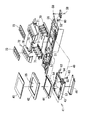
図5は、液晶表示部41及びその周辺の分解斜視図である。図に示すように、液晶表示部41は、液晶表示部41の筐体となる上カバー42及び下カバー43と、バックライト、導光板及び拡散シート等を一体に備えたLCD(Liquid Crystal Display)モジュール44と、上カバー42を覆う透明カバー45とを備えてなる。
FIG. 5 is an exploded perspective view of the liquid
下カバー43は、液晶表示部41の背面と周側面とを構成する平面視が略矩形の皿形状のものである。下カバー43の装置正面側の両側には、円筒状の軸受け50が形成されており、該軸受け50に操作パネル4側に略水平方向に突設された軸51,52が嵌め込まれるように挿入される。軸受け50及び軸51,52で形成される回動軸の軸線49を中心として、液晶表示部41が操作パネル4のベースプレート56に回動自在に支持される。下カバー43の装置正面側の略中央には背面側へ貫通孔53が形成されている。貫通孔53には、LCDモジュール44と、多機能装置1の装置本体側に設けられて上記制御部20を構成する制御基板とを電気的に接続するためのフラットケーブル54が挿通される。制御基板には、LCDコントローラ28が装備されており、LCDコントローラ28から電気信号を受けて所定の画面がLCDモジュール44の画面に表示される。
The
上カバー42は、平面視が下カバー43の平面視と略同等の矩形のものであり、液晶表示部41の前面と周側面とを構成する。下カバー43と上カバー42とが組み付けられることにより、LCDモジュール44を収容可能な内部空間を有する略直方体の筐体が形成される。上カバー42の前面には、LCDモジュール44の画面に対応した開口55が形成されている。この開口55により、上カバー42と下カバー43とで形成される筐体の内部空間に収容されたLCDモジュール44の画面が露出される。
The
透明カバー45は、平面視が上カバー42の平面視と略同等の矩形のものである。透明カバー45は、上カバー42の開口55に対応する領域が透明な樹脂からなり、その周囲の領域は不透明に着色されている。透明カバー45の透明な領域を通じて、開口55により露出されたLCDモジュール44の画面が視認される。上カバー42の開口55の周囲の領域、すなわち前面は透明カバー45の不透明な領域に覆われる。
The
軸51,52は、操作パネル4を構成するベースプレート56に固定されている。軸51は、ベースプレート56から立設されたリブ57と一体に形成されて、略水平方向に突出されている。軸52は、ベースプレート56とは別部材である軸部材58に一体に形成されている。軸部材58がベースプレート56にネジ59により固定されて、一対の対向する軸51,52が構成される。液晶表示部41を取り付ける際は、液晶表示部41の軸受け50の一方を軸51に嵌め込み、他方の軸受け50に軸部材58の軸52を嵌め込んで、該軸部材58をベースプレート56にネジ止めする。これにより、図6に示すように、液晶表示部41がベースプレート56に回動自在に軸支される。
The
図7は、軸51が突出された側からの軸部材58を示す斜視図である。図に示すように、軸部材58には、係止部材60が一体に形成されている。係止部材60は、軸線49の周方向に列設された複数の係止爪61を有する。係止爪61は、軸線49の径方向に外側に鋭角に突出する山形状のものであり、6つの係止爪61が軸線49の周方向に放射状に連続するように形成されている。連続する6つの係止爪61が、隣接する係止爪61間により5つの谷形状を形成している。この5つの谷形状により、液晶表示部41の起伏姿勢の位置決めがなされるが、それについては後述される。なお、係止爪61の数は特に限定されるものではなく、液晶表示部41の段階的な起伏姿勢の数により適宜変更されるものである。
FIG. 7 is a perspective view showing the
図5に示すように、液晶表示部41の下カバー43には、板バネ62がネジ63により固定される。板バネ62は、山折れ状の先端部64が軸受け50に近接する方向へ突出して固定される。軸受け50に軸部材58の軸52が嵌め込まれると、板バネ62の先端部64は、係止部材60に圧接する。
As shown in FIG. 5, a
図8は、係止部材60と板バネ62との係止状態を示している。液晶表示部41の軸受け50に軸52が嵌め込まれることにより、係止爪61が、軸52の周囲に周方向に並ぶ。液晶表示部41の軸受け50付近から突出された板バネ62は、山折れ状の先端部64を、隣接する係止爪61間の谷形状に合致するように、係止部材60に圧接する。
FIG. 8 shows a locked state between the locking
図に示すように、液晶表示部41が倒伏姿勢の場合には、板バネ62の先端部64は、隣接する6つの係止爪61により形成される5つの谷形状のいずれをも係止しない。倒伏姿勢の液晶表示部41を起立姿勢となる方向へ回動させるには、板バネ62の先端部64を、係止爪61の先端より軸52の径方向外側へ弾性変形させる必要がある。換言すれば、そのように板バネ62を弾性変形させる力を液晶表示部41に付与しなければ、液晶表示部41は回動されない。
As shown in the drawing, when the liquid
倒伏姿勢の液晶表示部41が起立される方向に回動されれば、液晶表示部41に付与された回動力により、板バネ62の先端部64は係止爪61に沿って軸52の径方向外側へ弾性変形する。そして、板バネ62の先端部64が、係止爪61の先端を超えると、該先端部64は、その係止爪61とそれに隣接する係止爪61との間の谷形状を係止するようにして、軸52の径方向内側へ復元する。板バネ62の先端部64が係止爪61間の谷形状を係止した状態から、液晶表示部41を起立方向又は倒伏方向のいずれに回動させるにも、板バネ62の先端部64を、係止爪61の先端より軸52の径方向外側へ弾性変形させる必要がある。換言すれば、液晶表示部41に更に回動させる力が付与されない限り、液晶表示部41は、板バネ62の先端部64が係止爪61間の谷形状を係止した状態で、その姿勢が維持される。
If the liquid
液晶表示部41が更に回動されると、前述と同様に、板バネ62の先端部64は、係止爪61に沿って軸52の径方向外側へ弾性変形して、板バネ62の先端部64が、所定の係止爪61の先端を超えると、該先端部64は、その係止爪61とそれに隣接する係止爪61との間の谷形状を係止するようにして、軸52の径方向内側へ復元する。そして、液晶表示部41が更に回動されない限り、液晶表示部41は、板バネ62の先端部64が係止爪61間の谷形状を係止した状態で、その姿勢が維持される。このような係止爪61と板バネ62との係合により、段階的な回動位置で液晶表示部41の姿勢が維持される。そして、段階的な回動位置を移動する際に、板バネ62の弾性変形と復元とが連続して行われ、液晶表示部41の回動にクリック感が生じる。
When the liquid
液晶表示部41が取り付けられたベースプレート56には、該液晶表示部41の周囲に操作キー40Aが取り付けられる。詳細には、図5に示すように、操作キー40Aは、パネルゲートアレイ27を構成する回路基板70と、ボタンとして押下されることにより回路基板70上の接点と接触するラバーキー71(キー部材)と、キートップとなるラバーキー71の上面を露出するように回路基板70及びラバーキー71を覆うキーカバー72と、キーカバー72の上面のキートップ周囲に貼り付けられる化粧カバー73とを具備する。これらがベースプレート56に組み付けられることにより、図1に示すように、液晶表示部41の周囲に操作キー40Aが構成される。
An operation key 40A is attached around the liquid
図9は、ラバーキー71の一方を示すものである。ラバーキー71は、例えばシリコンゴムのように、弾性変形可能であって絶縁性を有する弾性材からなる。図1に示すように、操作キー40Aは、液晶表示部41の左右にそれぞれ設けられており、図5に示すように、ラバーキー71は、左右一対が別部材として設けられている。図9は、図5における左側のラバーキー71を示している。一対のラバーキー71は、形状が略左右対称であるので、他方(図右側)のラバーキー71の説明は省略する。ラバーキー71は、回路基板70に接触する平板状のベース部74と、ベース部74から上方へ突接された角柱状のキー部75と、ベース部74の側縁であって一対のラバーキー71の内側となる位置に形成された摩擦摺動部76(摩擦摺動部材)とを有する。
FIG. 9 shows one of the
ベース部74は、図5に示すように回路基板70上の所定位置に接触するようにして、回路基板70と共にキーカバー72の裏面側に固定される。角柱形状のキー部75は、4つが並んで設けられており、キートップとなるキー部75の上面が押下されることにより、各キー部75の基端付近が撓んで座屈するように弾性変形する。これにより、キー部75の内側に設けられた導通部が回路基板70上に形成された2つの接点と接触して該接点を導通状態にし、この導通により各キー部75のオン/オフが回路基板70において電気的に認識される。
As shown in FIG. 5, the
摩擦摺動部76は、キー部75が並ぶ方向を長手方向としてベース部74から上方へ突出されている。ラバーキー71がキーカバー72に組み付けられると、摩擦摺動部76は、キーカバー72の案内溝78に沿って露出され、その長手方向が液晶表示部41の軸線49と直交する方向となる。摩擦摺動部76は、軸線49から遠ざかる方向へ向かって、突出高さが高くなるように形成されている。換言すれば、摩擦摺動部76は、軸線49から遠ざかる方向へ向かって高さが高くなるくさび形状をなしている。
The
図10は、液晶表示部41及び操作キー40Aの周辺の背面側の斜視図である。図に示すように、キーカバー72は、その幅方向中央に凹陥部77が形成されている。凹陥部77は、液晶表示部41の外形及び厚みに対応しており、液晶表示部41がキーカバー72に対して倒伏されると、図1に示すように、液晶表示部41が操作パネル4と同一面を形成するように、凹陥部77に収容される。凹陥部77の両側の隅部は、一部が切り欠かれて案内溝78が形成されている。図には、図右側の一方の案内溝78しか現れていないが、図左側の凹陥部77の隅部にも同様の案内溝78が形成されている。
FIG. 10 is a rear perspective view of the periphery of the liquid
前述したように、案内溝78にはラバーキー71の摩擦摺動部76が露出されている。摩擦摺動部76が案内溝78に沿って露出されることにより、案内溝78の溝幅が狭められている。また、摩擦摺動部76は、軸線49から遠ざかる方向へ向かって高さが高くなるくさび形状をなしているので、案内溝78の溝幅は、軸線49から遠ざかる方向へ向かって溝幅が狭くなっている。
As described above, the
図11は、防護カバー46(従動部材)を示している。防護カバー46は、液晶表示部41の下カバー43と略同幅の平板形状のものである。防護カバー46の一端側(図11手前側)の両側は一部が切り欠かれ、その切り欠き部分に突出するように支軸65がそれぞれ突設されている。防護カバー46の他端側(図11奥側)の両側には、外側へ向かって突出する係合片66がそれぞれ設けられている。
FIG. 11 shows the protective cover 46 (driven member). The
図10に示すように、防護カバー46は液晶表示部41の背面位置に取り付けられる。詳細には、液晶表示部41の下カバー43の軸線49から隔てた背面位置には軸支部67が形成されており、防護カバー46の支軸65が軸支部67に回動自在に取り付けられている。防護カバー46の係合片66は、キーカバー72に形成された案内溝78に嵌め込まれるように係合されている。
As shown in FIG. 10, the
係合片66は、案内溝78の溝幅より若干小さいものであり、案内溝78に係合された状態で案内溝78に従って摺動自在である。前述したように、案内溝78には、ラバーキー71の摩擦摺動部76が露出されており、摩擦摺動部76によって案内溝78の溝幅が狭めらるているので、係合片66は摩擦摺動部76を弾性変形させて圧接する。この圧接により、係合片66が案内溝78に従って摺動する際に所定の摩擦力が生じる。
The
液晶表示部41の背面位置に取り付けられた防護カバー46は、液晶表示部41の背面の軸線49付近を覆う。図5に示したように、液晶表示部41からは、LCDモジュール44と多機能装置1の装置本体側に設けられた制御基板とを電気的に接続するためのフラットケーブル54が延出されており、キーカバー72には、フラットケーブル54を挿通するための切り欠き79が形成されている。キーカバー72の背面側には回路基板70が配設されているので、クリップ等の金属製の異物が切り欠き79からキーカバー72内に浸入して回路基板70に接触することは、電気的不具合の原因となるので好ましくない。この切り欠き79が防護カバー46で覆われることにより、キーカバー72内に異物が進入することが防止される。
The
以下、液晶表示部41の起伏と防護カバー46の往復動について説明する。図12は、倒伏姿勢の液晶表示部41を示すものであり、図13は、起伏途中の任意の位置の液晶表示部41を示すものであり、図14は、起立姿勢の液晶表示部41を示すものである。なお、図においては、説明の便宜上、ラバーキー71やキーカバー72の一部が省略されている。
Hereinafter, the undulation of the liquid
液晶表示部41は、凹部50及び軸51,52により形成される回動軸の軸線49を中心として回動自在であり、装置本体の一部を構成するキーカバー72に対して起伏される。液晶表示部41の背面に軸支された防護カバー46は、液晶表示部41が回動されると共に回動される。防護カバー46の回動に伴って、係合片66が案内溝78を往復動する。つまり、防護カバー46の支軸65の回動が係合片66の往復動として伝達される。
The liquid
案内溝78には、摩擦摺動部76が露出されて、案内溝78の溝幅が狭められている。案内溝78に嵌め合わされた係合片66は、摩擦摺動部76を弾性変形して圧接されている。摩擦摺動部76は、この変形を弾性的に復元する力を有し、この弾性復元力により、係合片66が摩擦摺動部76を弾性変形させずに単に接触している際の摩擦力より大きな摩擦力が、係合片66の摺動に対して生じる。この摩擦力により、防護カバー46の往復動に対して摩擦抵抗が発生する。防護カバー46の往復動は、液晶表示部41の回動に従動するものなので、液晶表示部41の回動にも該摩擦抵抗が付与され、液晶表示部41の回動に所謂フリクションが生ずる。したがって、液晶表示部41が、図12〜図14のいずれの姿勢から回動して姿勢変化するにも、フリクション(摩擦抵抗)より大きな力が付与される必要があり、そのような力が付与されない限り、液晶表示部41は、自重等により回動せずに現在の姿勢を保持する。このようにして、液晶表示部41を所望の姿勢に保持する所謂チルト機構が実現されている。
The
図12〜図14に示すように、液晶表示部41が倒伏するほど、防護カバー46の係合片66は、案内溝78を軸線49(凹部50,軸52)から遠ざかる方向(図右側)へ摺動する。図14に示すように、液晶表示部41が起立姿勢であれば、液晶表示部41の自重Gによる液晶表示部41の回動方向の分力F1は比較的小さい。図13に示すように、液晶表示部41が起立姿勢から幾らか倒伏すれば、液晶表示部41の自重Gによる液晶表示部41の回動方向の分力F2は分力F1より大きくなる。図14に示すように、液晶表示部41が略水平となる倒伏姿勢であれば、液晶表示部41の自重Gはほぼすべてが回動方向の分力F3となる。つまり、液晶表示部41が倒伏するほど、液晶表示部41の自重Gによる倒伏方向の回動が生じやすく、液晶表示部41を所望の姿勢に維持するために大きなフリクションが必要になる。
As shown in FIGS. 12 to 14, the
案内溝78に露出された摩擦摺動部76は、液晶表示部41が倒伏する方向へ向かって、案内溝78の溝幅を狭めるようなくさび形状なので、液晶表示部41が倒伏する方向へ回動するに伴って、係合片66は摩擦摺動部76を大きく弾性変形させることになる。これにより、係合片66が液晶表示部41が倒伏する方向へ案内溝78を摺動するに伴って、摩擦摺動部76により生ずる摩擦力が連続的に大きくなる。これにより、液晶表示部41が倒伏姿勢に近い状態でも、その姿勢に液晶表示部41を保持するフリクションを発生させることができる。また、液晶表示部41を起伏する際に、液晶表示部41に生じるフリクションが回動範囲において一定になるので操作感が向上される。
The frictional sliding
また、図8に示したように、液晶表示部41が回動されると、板バネ62の先端部64が、係止部材60の係止爪61間を移動する。その際、板バネ62の先端部64が現在係止している係止爪61間から次の係止爪61間に移動する際に、係止爪61の形状に沿って弾性変形し、次の係止爪61間で復元する。液晶表示部41を回動し続けると、この板バネ62の弾性変形と復元とが連続的に行われ、板バネ62の先端部64が係止爪61間を係止する毎に、液晶表示部41の回動にクリック感が生じる。
As shown in FIG. 8, when the liquid
板バネ62が弾性変形してから復元する際には、板バネ62が振動するようにして弾性変形が収束的に収まる。この板バネ62の振動が、液晶表示部41に微小な回動方向の動きとして伝達される。これに伴って、防護カバー46にも微小な回動方向の動きが伝達されて、係合片66が案内溝78を振動するように往復動しようとするが、摩擦摺動部76により係合片66の摺動に対して摩擦力が付与されているので、防護カバー46の微小な動きが抑制される。これにより、液晶表示部41の微小な回動も抑制され、板バネ62の弾性変形及び復元による微小な振動のない良好なクリック感が実現される。
When the
このように、液晶表示部41の背面に回動自在に取り付けられた防護カバー46を液晶表示部41と共に回動させ、防護カバー46に設けられた係合片66を、キーカバー72の案内溝78に係合して摩擦摺動部76に圧接させながら摺動させることとしたので、係合片66の摺動に摩擦力が生じ、この摩擦力により防護カバー46の往復動に摩擦抵抗を付与して、液晶表示部41を所望の姿勢に保持するチルト機構が実現される。このチルト機構は、液晶表示部41の回動軸の軸線49を形成する凹部50及び軸51,52から離れた位置にある摩擦摺動部76と係合片66との摩擦力により実現されているので、液晶表示部41の軸線49付近の構成が簡易なものとなり、液晶表示部41周辺の小型化が実現される。
In this way, the
また、液晶表示部41の回動軸の軸線49から離れた位置で係合片66の摺動に摩擦力を付与させることにより、チルト機構を実現するための摩擦力を小さくすることができ、摩擦摺動部76の摩耗や音鳴きが防止される。
Further, by applying a frictional force to the sliding of the
また、摩擦摺動部76をラバーキー71に一体に形成することにより、摩擦摺動部76を安価に実現することができ、摩擦摺動部76をラバーキー71とともにキーカバー72に組み付けることができるので、部品点数を削減できるとともに組み立て工数の削減をも図ることができ、製造コストが低減される。さらに、案内溝78から塵埃や異物がキーカバー72の内部に進入しても、ラバーキー71のベース部74に受け止められて、回路基板70上に落下することが防止される。これにより、回路基板70に電気的な不具合が発生することが防止される。
Further, by forming the
なお、本実施の形態では、本発明に係る従動部材を防護カバー46として実現したが、該従動部材が防護カバー46の効果、すなわちキーカバー72の切り欠き79から異物の進入を防止する効果を奏するものに限定されないことは勿論である。したがって、平板状の防護カバー46の他に、例えば左右独立したアーム状の部材等により本発明に係る従動部材を実現することができる。
In the present embodiment, the driven member according to the present invention is realized as the
4・・・操作パネル(装置筐体)
40A・・・操作キー
41・・・液晶表示部
46・・・保護カバー(従動部材)
49・・・軸線(回動軸の軸線)
50・・・凹部50(回動軸)
52・・・軸(回動軸)
60・・・係止部材
61・・・係止爪
62・・・板バネ(弾性部材)
66・・・係合片
71・・・ラバーキー(キー部材)
76・・・摩擦摺動部(摩擦摺動部材)
78・・・案内溝
4 ... Operation panel (device housing)
40A ... operation key 41 ...
49 ... axis (axis of rotation axis)
50: Recess 50 (rotating shaft)
52 ... axis (rotating axis)
60 ... locking
66 ...
76 ... friction sliding part (friction sliding member)
78 ... Guide groove
Claims (6)
上記回動軸の軸線から隔てた上記表示部の背面位置に一端側が回動自在に取り付けられ、他端側に設けられた係合片が上記装置筐体に形成された案内溝に摺動自在に係合されることにより、上記表示部の起伏に従動して案内溝を往復動する従動部材と、
上記案内溝に沿って設けられて、上記従動部材の係合片に圧接することにより、該従動部材の往復動に所望の摩擦力を付与する摩擦摺動部材と、を具備し、
上記摩擦摺動部材は、上記表示部が倒伏する方向へ上記従動部材が移動する方向へ向かって、上記案内溝の溝幅を狭めるものである電子機器。 A display unit that is supported by the device housing so as to be rotatable about a rotation axis, and that can be raised and lowered with respect to the device housing;
One end side is pivotally attached to the rear position of the display unit separated from the axis of the pivot shaft, and an engagement piece provided on the other end side is slidable in a guide groove formed in the device casing. A driven member that reciprocates in the guide groove by following the undulation of the display unit,
A friction sliding member that is provided along the guide groove and applies a desired frictional force to the reciprocating motion of the driven member by being pressed against the engaging piece of the driven member ;
The electronic device in which the friction sliding member narrows the groove width of the guide groove in a direction in which the follower member moves in a direction in which the display unit lies down .
上記回動軸の軸線から隔てた上記表示部の背面位置に一端側が回動自在に取り付けられ、他端側に設けられた係合片が上記装置筐体に形成された案内溝に摺動自在に係合されることにより、上記表示部の起伏に従動して案内溝を往復動する従動部材と、 One end side is pivotally attached to the rear position of the display unit separated from the axis of the pivot shaft, and an engagement piece provided on the other end side is slidable in a guide groove formed in the device casing. A driven member that reciprocates in the guide groove by following the undulation of the display unit,
上記案内溝に沿って設けられて、上記従動部材の係合片に圧接して弾性変形することにより、該従動部材の往復動に所望の摩擦力を付与する弾性材である摩擦摺動部材と、 A friction sliding member which is provided along the guide groove and is an elastic material which applies a desired frictional force to the reciprocating motion of the driven member by pressing and elastically deforming the engagement piece of the driven member; ,
上記案内溝に隣接して、所望の指令を入力するための操作キーと、を具備し、 An operation key for inputting a desired command is provided adjacent to the guide groove,
上記操作キーを構成する弾性変形可能なキー部材と上記摩擦摺動部材とが一体に形成されたものである電子機器。 An electronic device in which the elastically deformable key member constituting the operation key and the friction sliding member are integrally formed.
隣り合う上記係止爪間に合致する山折れ状に先端が曲折された弾性部材が、上記係止部材に圧接するように上記表示部に突設され、
上記弾性部材の先端が、上記係止部材の係止爪間に係止されることにより、上記表示部が所定の姿勢に維持されるものである請求項1から5のいずれかに記載の電子機器。 A locking member having a plurality of locking claws arranged in the circumferential direction with respect to the axis of the rotation shaft is provided in the apparatus housing,
An elastic member whose tip is bent in a mountain shape that matches between the adjacent locking claws is protruded from the display unit so as to be in pressure contact with the locking member,
The electronic device according to any one of claims 1 to 5, wherein the display portion is maintained in a predetermined posture by the tip of the elastic member being locked between the locking claws of the locking member. machine.
Priority Applications (2)
| Application Number | Priority Date | Filing Date | Title |
|---|---|---|---|
| JP2005277314A JP4984468B2 (en) | 2005-09-26 | 2005-09-26 | Electronics |
| US11/534,658 US7352568B2 (en) | 2005-09-26 | 2006-09-24 | Electronic apparatus and image forming apparatus comprising such electronic apparatus |
Applications Claiming Priority (1)
| Application Number | Priority Date | Filing Date | Title |
|---|---|---|---|
| JP2005277314A JP4984468B2 (en) | 2005-09-26 | 2005-09-26 | Electronics |
Publications (2)
| Publication Number | Publication Date |
|---|---|
| JP2007086585A JP2007086585A (en) | 2007-04-05 |
| JP4984468B2 true JP4984468B2 (en) | 2012-07-25 |
Family
ID=37910683
Family Applications (1)
| Application Number | Title | Priority Date | Filing Date |
|---|---|---|---|
| JP2005277314A Expired - Fee Related JP4984468B2 (en) | 2005-09-26 | 2005-09-26 | Electronics |
Country Status (2)
| Country | Link |
|---|---|
| US (1) | US7352568B2 (en) |
| JP (1) | JP4984468B2 (en) |
Families Citing this family (11)
| Publication number | Priority date | Publication date | Assignee | Title |
|---|---|---|---|---|
| US8077679B2 (en) | 2001-03-28 | 2011-12-13 | Qualcomm Incorporated | Method and apparatus for providing protocol options in a wireless communication system |
| JP2007125837A (en) * | 2005-11-07 | 2007-05-24 | Funai Electric Co Ltd | Image forming apparatus and electronic apparatus |
| JP5024668B2 (en) * | 2007-07-10 | 2012-09-12 | 富士ゼロックス株式会社 | Image forming apparatus and information processing apparatus |
| JP2012071499A (en) * | 2010-09-29 | 2012-04-12 | Seiko Epson Corp | Recording apparatus |
| JP5436406B2 (en) | 2010-12-27 | 2014-03-05 | シャープ株式会社 | Image forming apparatus, program, and recording medium |
| JP5776336B2 (en) * | 2011-05-31 | 2015-09-09 | ブラザー工業株式会社 | Operating device |
| JP6613167B2 (en) * | 2016-02-19 | 2019-11-27 | シャープ株式会社 | Image forming apparatus |
| JP6932482B2 (en) * | 2016-04-25 | 2021-09-08 | キヤノン株式会社 | Image forming device |
| JP6977281B2 (en) * | 2017-03-17 | 2021-12-08 | 富士フイルムビジネスイノベーション株式会社 | Image forming device |
| JP6977282B2 (en) * | 2017-03-17 | 2021-12-08 | 富士フイルムビジネスイノベーション株式会社 | Image forming device |
| JP7471808B2 (en) | 2019-12-03 | 2024-04-22 | キヤノン株式会社 | Display device and image forming device |
Family Cites Families (22)
| Publication number | Priority date | Publication date | Assignee | Title |
|---|---|---|---|---|
| GB2104144B (en) * | 1981-08-21 | 1985-10-30 | Plessey Co Ltd | Improvements in or relating to assemblies with a movable part |
| JPH0320863Y2 (en) * | 1984-11-14 | 1991-05-07 | ||
| JPH01118189A (en) * | 1987-10-31 | 1989-05-10 | Nec Eng Ltd | Tilting mechanism |
| JP2715451B2 (en) * | 1988-06-27 | 1998-02-18 | セイコーエプソン株式会社 | Liquid crystal display devices and passenger cars |
| JPH0535739A (en) * | 1991-07-31 | 1993-02-12 | Mitsubishi Heavy Ind Ltd | Toll road terminal equipment |
| JPH0741078U (en) | 1993-12-28 | 1995-07-21 | 株式会社ニフコ | Rotating damper and lid opening / closing mechanism |
| JPH07217642A (en) | 1994-02-07 | 1995-08-15 | Sharp Corp | Tilt damper mechanism for information processor |
| JPH08160872A (en) * | 1994-12-05 | 1996-06-21 | Sharp Corp | Electronic equipment |
| JP3681247B2 (en) * | 1997-01-10 | 2005-08-10 | Necインフロンティア株式会社 | Angle adjustment device for display panel for tabletop equipment |
| JP2000227763A (en) | 1999-02-08 | 2000-08-15 | Matsushita Electric Ind Co Ltd | Electronic equipment |
| KR100327397B1 (en) * | 1999-09-20 | 2002-03-13 | 구자홍 | pedestal assembly for video display appliance |
| JP2002100883A (en) | 2000-09-22 | 2002-04-05 | Canon Inc | Electronic apparatus |
| JP2002369738A (en) * | 2001-06-17 | 2002-12-24 | Emiko Yanaga | Mirror with height adjusting function |
| JP2003130036A (en) * | 2001-10-25 | 2003-05-08 | Sharp Corp | Electronic device |
| JP3730564B2 (en) * | 2001-11-08 | 2006-01-05 | パイオニア株式会社 | Electronics |
| US6766994B2 (en) * | 2002-04-05 | 2004-07-27 | 3M Innovative Properties Company | Stabilized flat panel touch monitor |
| JP2004053768A (en) | 2002-07-17 | 2004-02-19 | Kenwood Corp | Tilting up structure for display |
| KR100867108B1 (en) * | 2002-09-19 | 2008-11-06 | 삼성전자주식회사 | Installation Equipment for Display and Jig for Installation Equipment |
| JP2004304736A (en) * | 2003-04-01 | 2004-10-28 | Sony Corp | Angle adjusting mechanism of electronic device |
| JP4324436B2 (en) * | 2003-09-25 | 2009-09-02 | パナソニック株式会社 | Electronics |
| US7356954B2 (en) * | 2003-12-01 | 2008-04-15 | Fujitsu Ten Limited | In-vehicle display apparatus |
| JP4658849B2 (en) * | 2006-03-31 | 2011-03-23 | ブラザー工業株式会社 | Electronics |
-
2005
- 2005-09-26 JP JP2005277314A patent/JP4984468B2/en not_active Expired - Fee Related
-
2006
- 2006-09-24 US US11/534,658 patent/US7352568B2/en active Active
Also Published As
| Publication number | Publication date |
|---|---|
| JP2007086585A (en) | 2007-04-05 |
| US20070080957A1 (en) | 2007-04-12 |
| US7352568B2 (en) | 2008-04-01 |
Similar Documents
| Publication | Publication Date | Title |
|---|---|---|
| JP4984468B2 (en) | Electronics | |
| JP4962264B2 (en) | Operation device and image recording device | |
| EP3273300B1 (en) | Display panel for an image forming apparatus | |
| JP4552825B2 (en) | Image reading device | |
| JP4797694B2 (en) | Multi-function device | |
| US20060082958A1 (en) | Electronic equipment | |
| JP2007188416A (en) | Radio card reader and image forming apparatus using the same | |
| US6661539B1 (en) | Vertically oriented document scanner | |
| US7580249B2 (en) | Image forming apparatus | |
| JP2002325155A (en) | Image reader | |
| JP4577002B2 (en) | Electrical equipment and composite printer device | |
| JP6982843B2 (en) | Hinge | |
| TWI830654B (en) | Hinge and business machine using the same | |
| JP2016148815A (en) | Hinge | |
| JP4341352B2 (en) | Hinge and image input / output device having the same | |
| JP3596527B2 (en) | Image forming device | |
| JP5331674B2 (en) | Image forming apparatus | |
| JP2007086357A (en) | Image forming apparatus | |
| JP5183862B2 (en) | Scanner printer device and scanner mechanism | |
| JP2008152053A (en) | Image forming apparatus | |
| JP2016055436A (en) | Panel tilt mechanism and recording device | |
| JP2003345461A (en) | Information processor | |
| JP2007049544A (en) | Combined printer | |
| JP2008099161A (en) | Scanner device and image forming apparatus using the same | |
| JP2009080409A (en) | Turning device and image recorder |
Legal Events
| Date | Code | Title | Description |
|---|---|---|---|
| A621 | Written request for application examination |
Free format text: JAPANESE INTERMEDIATE CODE: A621 Effective date: 20080714 |
|
| A131 | Notification of reasons for refusal |
Free format text: JAPANESE INTERMEDIATE CODE: A131 Effective date: 20110712 |
|
| A521 | Request for written amendment filed |
Free format text: JAPANESE INTERMEDIATE CODE: A523 Effective date: 20110912 |
|
| TRDD | Decision of grant or rejection written | ||
| A01 | Written decision to grant a patent or to grant a registration (utility model) |
Free format text: JAPANESE INTERMEDIATE CODE: A01 Effective date: 20120403 |
|
| A01 | Written decision to grant a patent or to grant a registration (utility model) |
Free format text: JAPANESE INTERMEDIATE CODE: A01 |
|
| A61 | First payment of annual fees (during grant procedure) |
Free format text: JAPANESE INTERMEDIATE CODE: A61 Effective date: 20120416 |
|
| R150 | Certificate of patent or registration of utility model |
Ref document number: 4984468 Country of ref document: JP Free format text: JAPANESE INTERMEDIATE CODE: R150 Free format text: JAPANESE INTERMEDIATE CODE: R150 |
|
| FPAY | Renewal fee payment (event date is renewal date of database) |
Free format text: PAYMENT UNTIL: 20150511 Year of fee payment: 3 |
|
| LAPS | Cancellation because of no payment of annual fees |