JP2005299745A - Vibration control supporting device - Google Patents
Vibration control supporting device Download PDFInfo
- Publication number
- JP2005299745A JP2005299745A JP2004114137A JP2004114137A JP2005299745A JP 2005299745 A JP2005299745 A JP 2005299745A JP 2004114137 A JP2004114137 A JP 2004114137A JP 2004114137 A JP2004114137 A JP 2004114137A JP 2005299745 A JP2005299745 A JP 2005299745A
- Authority
- JP
- Japan
- Prior art keywords
- component
- signal component
- vibration
- signal
- air chamber
- Prior art date
- Legal status (The legal status is an assumption and is not a legal conclusion. Google has not performed a legal analysis and makes no representation as to the accuracy of the status listed.)
- Pending
Links
Images


Landscapes
- Combined Devices Of Dampers And Springs (AREA)
Abstract
Description
本発明は、防振支持装置に関するものであり、特に大気圧と負圧とを交互に導入して空気室を膨張及び収縮することにより振動体からの振動を抑制するものに好適なものである。 The present invention relates to an anti-vibration support device, and is particularly suitable for a device that suppresses vibration from a vibrating body by alternately introducing atmospheric pressure and negative pressure to expand and contract an air chamber. .
このような防振支持装置としては、例えば内部に空気室を設け、その空気室に大気圧と負圧とを交互に供給して、その気圧の変動によって当該空気室を膨張及び収縮し、これにより振動体からの振動伝達特性を制御可能とすると共に、前記大気圧と負圧とを切換える切換手段と空気室との途中に個別の収容空間を設け、この収容空間内の脈動共鳴効果を利用して空気室内の圧力変動による高調波成分が発生しないようにしたものがある(例えば特許文献1)。
しかしながら、前記従来の装置では、個別に設けた収容空間の脈動の共鳴効果を利用しており、収容空間の形状及び寸法で決まる特定の周波数に対してのみ振動抑制の効果を発揮するものであるので、或る特定周波数の高調波成分の発生を抑制防止することはできても、その他の高調波成分の発生は抑制防止できないことになる。
本発明は、上記のような問題点に着目してなされたものであり、様々な周波数の高調波成分の発生を抑制防止可能な防振支持装置を提供することを目的とするものである。
However, the conventional device uses the resonance effect of the pulsation of the accommodation space provided individually, and exhibits the effect of suppressing vibration only for a specific frequency determined by the shape and size of the accommodation space. Therefore, even if generation of harmonic components of a specific frequency can be suppressed and prevented, generation of other harmonic components cannot be suppressed and prevented.
The present invention has been made paying attention to the above problems, and an object thereof is to provide an anti-vibration support device that can suppress and prevent the generation of harmonic components of various frequencies.
上記課題を解決するために、本発明の防振支持装置は、振動体と車両との間に設けられた防振機構部であり、前記防振機構部の内部に形成され、供給される気圧の変動に応じて膨張及び収縮することで、前記防振機構部を介して振動体と車体に力を加えることができる空気室と、前記空気室に大気圧又は略大気圧及び大気圧と圧力差のある気圧の何れか一方を供給する切換手段と、前記切換手段に制御信号を出力することにより、前記空気室内に圧力の異なる空気を給排して前記振動体の振動を抑制する力を出力するように前記切換手段を制御する制御手段とを備え、前記制御手段は、前記振動体の振動を抑制する第1信号成分と、当該第1信号成分に対し、周期が短い特性の第2信号成分とに基づいて前記制御信号を創成出力することを特徴とするものである。 In order to solve the above-described problems, a vibration isolating support device according to the present invention is a vibration isolating mechanism portion provided between a vibrating body and a vehicle, and is formed and supplied inside the anti-vibration mechanism portion. An air chamber that can apply force to the vibrating body and the vehicle body via the vibration isolation mechanism by expanding and contracting according to the fluctuations of the atmospheric pressure, and atmospheric pressure or substantially atmospheric pressure and atmospheric pressure and pressure to the air chamber The switching means for supplying any one of the differential atmospheric pressures, and the control signal is output to the switching means, whereby the force for suppressing the vibration of the vibrating body by supplying and discharging air having different pressures in the air chamber. Control means for controlling the switching means to output, the control means, a first signal component for suppressing vibration of the vibrating body, and a second signal having a short cycle with respect to the first signal component. And generating and outputting the control signal based on the signal component. It is an.
而して、本発明の防振支持装置によれば、切換手段に制御信号を出力することにより、空気室内に圧力の異なる空気を給排して振動伝達特性を制御するにあたり、振動体の振動を抑制する第1信号成分と、当該第1信号成分に対し、周期の短い特性の第2信号成分とに基づいて前記制御信号を創成出力する構成としたため、前記第2信号成分を、第1信号成分による空気室の圧力変動に伴う高調波成分を抑制するものとすることで、多様な周波数の高調波成分を抑制防止することが可能となる。 Thus, according to the anti-vibration support device of the present invention, the vibration signal of the vibrating body is controlled by supplying a control signal to the switching means to control the vibration transmission characteristics by supplying and discharging air having different pressures in the air chamber. Since the control signal is generated and output based on the first signal component for suppressing the first signal component and the second signal component having a short cycle characteristic with respect to the first signal component, the second signal component is changed to the first signal component. By suppressing harmonic components accompanying the pressure fluctuation of the air chamber due to signal components, it is possible to suppress and prevent harmonic components of various frequencies.
次に、本発明の防振支持装置の第1実施形態について図面を参照しながら説明する。
図1は、本実施形態の内燃機関防振支持装置の概略構成図であり、図中の符号1は直列4気筒のガソリンエンジンで構成された内燃機関である。この内燃機関1は、本体となるエンジンブロック2と、エンジンブロック2内に形成されたシリンダ3と、シリンダ3内を摺動するピストン4と、ピストン4に連結されたコネクティングロッド5と、コネクティングロッド5に連結され、内燃機関1の動力を取出すクランクシャフト6とを備えている。
Next, a first embodiment of the anti-vibration support device of the present invention will be described with reference to the drawings.
FIG. 1 is a schematic configuration diagram of an internal combustion engine anti-vibration support device of the present embodiment, and reference numeral 1 in the drawing is an internal combustion engine configured by an inline 4-cylinder gasoline engine. The internal combustion engine 1 includes an
また、内燃機関1は、大気を吸入する吸気通路7と、排気を排出する排気通路8とを有している。吸気通路7の吸入口7a側には、エアクリーナ9が設けられており、内部に設けられたペーパエレメント11によって吸入する大気を浄化している。また、吸気通路7におけるエアクリーナ9の下流側には、運転者のアクセル操作量に応じて内燃機関1の吸気量を調整するスロットルバルブ10が設けられており、スロットルバルブ10の開度が小さいときには、吸入抵抗が増加してスロットルバルブ10の下流側に負圧が発生するように構成されている。
The internal combustion engine 1 also has an intake passage 7 for sucking in air and an exhaust passage 8 for discharging exhaust. An
また、内燃機関1は、能動型防振支持器12によって車体に支持されている。この能動型防振支持器12内には、変動気圧供給路14から供給される気圧の変化に応じて容積が弾性的に膨張及び収縮する空気室15が形成されている。この実施形態では、例えば図1において内燃機関1が上方に移動しようとするときに空気室15に負圧を供給し、空気室15が収縮することで、内燃機関1を下方に移動させる力を発生させる、内燃機関1が下方に移動しようとするときに空気室15に大気圧を供給し、空気室15が膨張することで、内燃機関1を上方に移動させる力を発生させることにより、内燃機関1の上下方向振動を打ち消す向きに力が発生するので、内燃機関1の振動の車体への振動伝達特性を抑制することが可能となる。
The internal combustion engine 1 is supported on the vehicle body by an active
能動型防振支持器12の詳細を図2に示す。この能動型防振支持器12は、略円筒型の本体ケース32を有し、この本体ケース32に接続されたブラケット37が車体に固定される。本体ケース32の上部には、ゴム等の弾性体からなる弾性部材39が嵌め込まれている。この弾性部材39に連結具31が遊動可能に取付けられ、この連結具31が内燃機関1に固定されている。
The details of the
一方、本体ケース32の内側底部には、ゴム等の弾性体からなる緩衝部材33が充填されている。この緩衝部材33と前記弾性部材39との間の空間を隔離部材34で隔離して、その上下に、オイル等の流体が充填される液室40、41が形成されている。なお、二つの液室40、41は、図示しない小径の通路によって連通されており、両液室40、41間を流体が往来可能となっている。
On the other hand, the inner bottom portion of the
前記二つの液室40、41を隔離する隔離部材34の上面には、シート状のダイヤフラム35が配設され、固定具36によって、その周縁部が隔離部材34に固定されている。また、隔離部材34には、上側液室40側の面から本体ケース32の外部まで連通する連通路38が形成され、この連通路38に、前記変動気圧供給路14が接続されている。従って、前記変動気圧供給路14から連通路38を通して隔離部材34の上面に空気が供給されると、ダイヤフラム35が膨張して、隔離部材34との間に空気室15が形成される。空気室15が膨張すると、弾性部材39、連結具31を介して、内燃機関1を上方に押し上げる力が作用し、空気室15が収縮すると、内燃機関1を下方に引き下げる力が作用する。
A sheet-
前記吸気管路7のうち、スロットルバルブ10の上流側からは大気圧導入路21が分岐されると共に、スロットルバルブ10の下流側からは負圧導入路20が分岐され、それらは、切換弁19を介して変動気圧供給路14に接続されている。従って、切換弁19を切換えると大気圧導入路21又は負圧導入路20の何れかが変動気圧供給路14に接続され、その結果、前記空気室15に供給される気圧を大気圧と負圧とに切換えることができる。
In the intake pipe 7, an atmospheric
切換弁19は、電磁ソレノイドを備えており、この電磁ソレノイドに対して、後述するコントローラ24からの制御信号により駆動制御されている。即ち、切換弁19は、電磁ソレノイドが非通電(以下、OFFとも記す)状態で変動気圧供給路14と大気圧導入路21とを連通して空気室15に大気圧を供給し、電磁ソレノイドが通電(以下、ONとも記す)状態で変動気圧供給路14と負圧導入路20とを連通して空気室15に負圧を供給するように構成されている。従って、切換弁19をOFF状態とON状態を交互に切換えるように制御することにより、能動型防振支持器12の空気室15に対して、大気圧と負圧とに変動する気圧を供給できる。
The
また、クランクシャフト6には、その回転角信号を検出する電磁ピックアップ式のクランク角センサが取付けられている。このクランク角センサは、クランクシャフトと共に回転するロータの外周面に10°間隔で形成されたセレーションを検出して、回転角信号をクランク角信号として出力する。また、セレーションには、180°間隔で2つの欠歯部が形成されているので、出力されるクランク角信号からクランクシャフト6の回転位置を把握できるように構成されている。 The crankshaft 6 is provided with an electromagnetic pickup type crank angle sensor for detecting the rotation angle signal. This crank angle sensor detects serrations formed at 10 ° intervals on the outer peripheral surface of a rotor that rotates together with the crankshaft, and outputs a rotation angle signal as a crank angle signal. Further, since the serration is formed with two missing teeth at intervals of 180 °, the rotation position of the crankshaft 6 can be grasped from the output crank angle signal.
また、内燃機関1は、マイクロコンピュータ等の演算処理装置を備えたエンジンコントローラによって運転状態が制御され、その制御出力には燃料噴射器(インジェクタ)による燃料噴射量(燃料噴射時間)や点火栓による点火時期等も含まれている。そこで、エンジンコントローラによる燃料噴射信号、前記クランク角センサからのクランク角信号が、例えばマイクロコンピュータ等の演算処理装置を備えて構成されたコントローラ24に入力される。このコントローラ24は、内燃機関1が運転状態にあるときに、図3に示す連通制御処理を実行して、前述した切換弁19に対する制御信号を創成出力するように構成されている。
The operation state of the internal combustion engine 1 is controlled by an engine controller equipped with an arithmetic processing unit such as a microcomputer, and the control output is based on a fuel injection amount (fuel injection time) by a fuel injector (injector) and a spark plug. Ignition timing etc. are also included. Therefore, a fuel injection signal from the engine controller and a crank angle signal from the crank angle sensor are input to a
次に、コントローラ24で実行する連通制御処理を、図3のフローチャートに従って説明する。
この連通制御処理は、まずステップS1で、クランク角信号及び燃料噴射信号を読込む。このうち、クランク角信号は、例えば図4に示すように、クランクシャフト6の回転に応じて、10°CA(クランク角)毎に1パルスが出力されると共に、このパルス信号が180°CA毎に非出力となる。
次にステップS2に移行して、ステップS1で読込んだクランク角信号に基づいて、内燃機関1の回転速度NEを算出する。
次にステップS3に移行して、切換弁19に対する制御信号を構成するパルス成分のデューティ比及び位相を算出する。このデューティ比及び位相の算出方法については後段に詳述する。
Next, the communication control process executed by the
In this communication control process, first, in step S1, a crank angle signal and a fuel injection signal are read. Among these, as shown in FIG. 4, for example, as shown in FIG. 4, one pulse is output every 10 ° CA (crank angle) according to the rotation of the crankshaft 6, and this pulse signal is output every 180 ° CA. No output.
Next, the process proceeds to step S2, and the rotational speed NE of the internal combustion engine 1 is calculated based on the crank angle signal read in step S1.
Next, the process proceeds to step S3, and the duty ratio and phase of the pulse component constituting the control signal for the
次にステップS4に移行して、前記ステップS3で算出されたデューティ比及び位相に基づいた制御信号を創成出力することにより、切換弁19を駆動制御してからメインプログラムに復帰する。この制御信号の創成方法についても後段に詳述する。
次に、前記切換弁19に対する制御信号のデューティ比及び位相の算出方法並びにそれらに基づいた切換弁制御信号の創成方法について説明する。
Next, the process proceeds to step S4, where a control signal based on the duty ratio and phase calculated in step S3 is generated and output to drive the
Next, a method for calculating the duty ratio and phase of the control signal for the
まず、内燃機関の振動形態について考える。本実施形態では4気筒ガソリンエンジンを内燃機関として用いている。内燃機関の振動の起振力には、燃焼爆発の圧力変動に起因する燃焼起振力と、ピストンやコネクティングロッド等がシリンダ内を往復移動することによって発生する慣性起振力とがある。燃焼によって発生する圧力変動は、ピストンからクランクシャフトに伝達されてトルク変動を生じる。このとき、エンジンブロックは、ピストンからトルク反力を受けるため、エンジンブロックにはクランクシャフトの軸周りの回転振動が発生する。これが燃焼起振力による内燃機関のロール振動である。この燃焼起振力は燃焼爆発に起因するものであるから、その大きさは燃料噴射量に応じて変化し、その位相は点火時期及び燃焼噴射量によって決まる。 First, the vibration mode of the internal combustion engine will be considered. In this embodiment, a 4-cylinder gasoline engine is used as the internal combustion engine. The vibration generation force of the internal combustion engine includes a combustion vibration force due to pressure fluctuations of combustion explosion and an inertia vibration force generated by reciprocating movement of a piston, a connecting rod, and the like in the cylinder. The pressure fluctuation generated by the combustion is transmitted from the piston to the crankshaft to cause torque fluctuation. At this time, since the engine block receives a torque reaction force from the piston, rotational vibration around the axis of the crankshaft is generated in the engine block. This is the roll vibration of the internal combustion engine caused by the combustion excitation force. Since this combustion excitation force is caused by combustion explosion, its magnitude changes according to the fuel injection amount, and its phase is determined by the ignition timing and the combustion injection amount.
また、ピストンは、燃焼爆発の力を受けてシリンダ内を往復移動し、このときに発生する往復慣性力の反力によってエンジンブロックがシリンダの軸方向に振動する。これが内燃機関の慣性起振力による振動である。従って、この慣性起振力による振動は、クランクシャフトの回転速度の2乗に比例して大きくなり、位相はクランクシャフトの回転角に対して一定の位相関係となる。つまり、慣性起振力の変数はクランクシャフトの回転速度、即ち内燃機関回転速度NEとなる。 The piston receives a combustion explosion force and reciprocates in the cylinder, and the engine block vibrates in the axial direction of the cylinder by the reaction force of the reciprocating inertia force generated at this time. This is the vibration due to the inertial excitation force of the internal combustion engine. Therefore, the vibration due to the inertial excitation force increases in proportion to the square of the rotation speed of the crankshaft, and the phase has a constant phase relationship with the rotation angle of the crankshaft. That is, the variable of the inertial excitation force is the rotational speed of the crankshaft, that is, the internal combustion engine rotational speed NE.
このように、内燃機関の振動形態は、燃料噴射信号等の内燃機関の負荷を示す情報と、内燃機関回転速度NEやクランクシャフトの回転角、即ちクランク角とから把握することができる。図4に示す燃料噴射信号(INJ信号)は、前記エンジンコントローラから入力される信号であり、例えば#1、#2…は、夫々、気筒番号を示している。この実施形態では、燃料噴射器へのINJ信号がLoのときに開弁して燃料が噴射される構成となっている。これらの燃料噴射信号から燃料噴射時間が得られ、この燃料噴射時間に燃料噴射器の流量を乗ずれば燃料噴射量が得られる。 Thus, the vibration mode of the internal combustion engine can be grasped from the information indicating the load of the internal combustion engine such as a fuel injection signal, and the internal combustion engine rotational speed NE and the rotation angle of the crankshaft, that is, the crank angle. The fuel injection signal (INJ signal) shown in FIG. 4 is a signal input from the engine controller. For example, # 1, # 2,... Indicate the cylinder number. In this embodiment, when the INJ signal to the fuel injector is Lo, the valve is opened and fuel is injected. The fuel injection time is obtained from these fuel injection signals, and the fuel injection amount is obtained by multiplying the fuel injection time by the flow rate of the fuel injector.
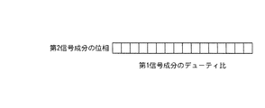
そこで、この燃料噴射時間と前記内燃機関回転速度NEとを用い、図5に示す三次元制御マップから、能動型防振支持器12による防振作用のうち、前記内燃機関の起振力を抑制するための成分のデューティ比A/Bを設定する。デューティ比A/Bが大きいほど、能動型防振支持器12の制振力が大きくなる。合わせて、燃料噴射時間と内燃機関回転速度NEとを用い、図6に示す三次元制御マップから、能動型防振支持器12による防振作用のうち、前記内燃機関の起振力を抑制するための成分の位相Cを設定する。
Therefore, using this fuel injection time and the internal combustion engine rotational speed NE, the vibration generating force of the internal combustion engine is suppressed from the vibration isolation action by the active
これらのデューティ比及び位相から設定される内燃機関起振力抑制成分は、図4に示す第1信号成分となる。この第1信号成分の位相基準は、前記クランク角信号のうち、180°CA毎の欠歯部後1パルス目の立下りとする。第1信号成分の周期Bは、各気筒の燃焼爆発周期に一致するので、ガソリン4気筒エンジンを内燃機関とする本実施形態では180°CAとなる。そこで、この第1信号成分の基本次数成分を、振幅がA、角周波数がωの正弦波Asinωtで表し、当該第1信号成分の基本次数成分が最大となるπ/2ω周期における前記位相基準に対する位相ずれを前記位相Cとし、これを第1信号成分のパルス波の中央とする。そして、この位相Cの時点から前後(図では左右)にデューティ比A/Bを振り分けて第1信号成分のパルス波を設定する。 The internal combustion engine excitation force suppression component set from these duty ratios and phases is the first signal component shown in FIG. The phase reference of the first signal component is the falling edge of the first pulse after the missing tooth portion every 180 ° CA in the crank angle signal. Since the period B of the first signal component coincides with the combustion explosion period of each cylinder, it is 180 ° CA in this embodiment in which the gasoline four-cylinder engine is an internal combustion engine. Therefore, the basic order component of the first signal component is represented by a sine wave Asinωt having an amplitude of A and an angular frequency of ω, and the phase reference with respect to the phase reference in the π / 2ω period in which the basic order component of the first signal component is maximized. The phase shift is the phase C, which is the center of the pulse wave of the first signal component. Then, the pulse wave of the first signal component is set by distributing the duty ratio A / B before and after the phase C (left and right in the figure).
一方、切換弁19のON/OFFにより発生し、空気室15に供給される圧力変動がパルス波になるため、内燃機関の起振力を抑制する圧力変動を第1信号成分とすると、当該第1信号成分に対してn次の高調波成分の圧力変動が誘発される。圧力変動の高調波成分のレベル及び位相は、第1信号成分のパルス波のデューティ比によって決まる。ここでは、n=2として、第1信号成分の2次成分について考える。この第1信号成分の2次成分は、当然ながら、第1信号成分の基準次数成分の2倍の周波数となる。高調波成分の特徴は、第1信号成分の基準次数成分の最大値と高調波成分の最大値とが一致するか、或いは第1信号成分の基準次数成分の最大値と高調波成分の最小値とが一致するかの何れかである点にある。
On the other hand, since the pressure fluctuation generated by ON / OFF of the switching
まず、図4に示すように、第1信号成分の基準次数成分の最大値と高調波成分(2次成分)の最大値とが一致する場合について考える。この高調波成分、即ち第1信号成分の2次成分を抑制するための基準次数成分は、当該2次成分と逆位相でなければならない。そこで、この2次成分を抑制する成分を第2信号成分とすると、その基準次数成分が最大値となる時点で第2信号成分のパルス波を出力すれば、2次成分による高調波振動を抑制することが可能となる。この場合は、第1信号成分の基準次数成分の最大値と2次成分の最大値とが一致しているので、第2信号成分の基準次数成分が最大となるのは、前記第1信号成分の位相Cに対して、当該第1信号成分の周期の1/4か、或いは3/4分だけずれた時点である。これをn次高調波成分に変換すると、mを整数として、(2m−1)/(2n×周期)となる。(2m−1)は奇数を示す。また、このn次高調波成分を抑制する第2信号成分のパルスの大きさ、即ちデューティ比E/Bは、第1信号成分のパルスの大きさ、即ち前記デューティ比A/Bに依存する。そこで、本実施形態では、図7に示す制御マップに従って、第1信号成分のデューティ比A/Bに応じた第2信号成分のデューティ比E/Bを設定する。また、前述のように、n次高調波成分の位相は、第1信号成分のデューティ比A/Bに応じて決まるので、図8に示す制御マップに従って、第1信号成分のデューティ比A/Bに応じた第2信号成分の位相を設定する。 First, as shown in FIG. 4, consider a case where the maximum value of the reference order component of the first signal component matches the maximum value of the harmonic component (secondary component). The reference order component for suppressing the higher harmonic component, that is, the second order component of the first signal component, must have an opposite phase to the second order component. Therefore, assuming that the component that suppresses the secondary component is the second signal component, if the pulse wave of the second signal component is output when the reference order component reaches the maximum value, the harmonic vibration due to the secondary component is suppressed. It becomes possible to do. In this case, since the maximum value of the reference order component of the first signal component matches the maximum value of the secondary component, the reference order component of the second signal component is maximized. The phase C is shifted by 1/4 or 3/4 of the period of the first signal component. When this is converted into an nth-order harmonic component, m is an integer and (2m−1) / (2n × period). (2m-1) indicates an odd number. The pulse magnitude of the second signal component that suppresses the nth-order harmonic component, that is, the duty ratio E / B, depends on the pulse magnitude of the first signal component, that is, the duty ratio A / B. Therefore, in the present embodiment, the duty ratio E / B of the second signal component corresponding to the duty ratio A / B of the first signal component is set according to the control map shown in FIG. Further, as described above, since the phase of the n-th harmonic component is determined according to the duty ratio A / B of the first signal component, the duty ratio A / B of the first signal component is determined according to the control map shown in FIG. The phase of the second signal component corresponding to is set.
これに対し、第1信号成分の基準次数成分の最大値と高調波成分の最小値とが一致する場合には、前記第1信号成分の位相Cに対する第2信号成分の位相ずれは、kを整数として、2k/(2n×周期)となる。2kは偶数を示す。
このようにして設定された第1信号成分と第2信号成分とを合成して、図4に示すような切換弁制御信号を創成出力する。この際、本実施形態のように切換弁19が単一である場合、第1信号成分のパルス波と第2信号成分のパルス波とが重合すると、高調波成分による振動を抑制することができない。図4に示すように、第1信号成分の2次成分だけを考えると、第2信号成分のパルス波を発生する機会は、第1信号成分の間に2回しかないが、高調波成分の次数が高次になればなるほど、第2信号成分のパルス波を発生する機会は増える。従って、抑制した高調波成分の次数が予め設定されたら、第2信号成分のパルス波が第1信号成分のパルス波に重合しないように、第2信号成分のパルス波を設定する。なお、第1信号成分のパルス波間に出力する第2信号成分のパルス波数はいくつでもよい。また、制御信号出力に対し、能動型防振支持装置12が制振力を発生するまでの応答特性に応じて第2信号成分を補正するようにすれば、高調波成分による振動の抑制効果をより一層高めることができる。
On the other hand, when the maximum value of the reference order component of the first signal component matches the minimum value of the harmonic component, the phase shift of the second signal component with respect to the phase C of the first signal component is k. As an integer, 2k / (2n × period). 2k indicates an even number.
The first signal component and the second signal component set in this way are combined to generate and output a switching valve control signal as shown in FIG. At this time, when the switching
本実施形態の内燃機関防振支持装置によれば、内燃機関の起振力を抑制する、つまり内燃機関の振動形態に応じた第1信号成分と、当該第1信号成分とは位相や大きさ等の特性の異なる第2信号成分とに基づいて切換弁制御信号を創成し、この制御信号によって、内燃機関から車体への振動伝達特性を制御する空気室への気圧を切換える切換弁を制御する構成としたため、前記第2信号成分を、第1信号成分の高調波成分を抑制する信号成分とすることにより、内燃機関の起振力による振動及び高調波成分による振動を同時に抑制することができ、また抑制する高調波成分の周波数を適宜設定することで、多様な高調波成分の振動をいくつでも、或いは連続して抑制することができる。 According to the internal combustion engine vibration isolating support device of the present embodiment, the first signal component corresponding to the vibration form of the internal combustion engine and the first signal component are suppressed in phase and magnitude. A switching valve control signal is created based on the second signal component having different characteristics, and the switching valve that switches the pressure to the air chamber that controls the vibration transmission characteristic from the internal combustion engine to the vehicle body is controlled by this control signal. Since the second signal component is a signal component that suppresses the harmonic component of the first signal component, the vibration due to the excitation force of the internal combustion engine and the vibration due to the harmonic component can be suppressed simultaneously. In addition, by appropriately setting the frequency of the harmonic component to be suppressed, the vibration of various harmonic components can be suppressed any number or continuously.
また、第2信号成分の基本次数成分を、第1信号成分によって発生する空気室内の圧力変動の高調波成分に対して逆位相又は略逆位相となる位相特性とすることにより、高調波成分による振動を確実に抑制することができる。
また、nを2以上の整数とし、且つ第1信号成分によって発生する空気室内の圧力変動のn次高調波成分を抑制する場合、振幅がA、角周波数がωの第1信号成分の基本次数成分Asinωtをπ/2ω周期分位相をずらした位相基準、つまり第1信号成分の基本次数成分の最大値に対し、m及びkを自然数として、略(2m−1)/2n周期又は略2k/2n周期分、位相をずらして第2信号成分を設定することにより、あらゆる次数の高調波成分、つまり多様な周波数の高調波成分による振動を抑制することが可能となる。
Further, the fundamental order component of the second signal component is made to have a phase characteristic that is opposite or substantially opposite to the harmonic component of the pressure fluctuation in the air chamber generated by the first signal component. Vibration can be reliably suppressed.
Further, when n is an integer of 2 or more and the nth-order harmonic component of the pressure fluctuation in the air chamber generated by the first signal component is suppressed, the basic order of the first signal component having an amplitude of A and an angular frequency of ω. With respect to the phase reference in which the phase of the component Asin ωt is shifted by π / 2ω period, that is, the maximum value of the basic order component of the first signal component, m and k are natural numbers, approximately (2m−1) / 2n period or approximately 2k / By setting the second signal component by shifting the phase by 2n periods, it is possible to suppress vibrations caused by harmonic components of all orders, that is, harmonic components of various frequencies.
また、切換弁が単一であっても、第1信号成分と第2信号成分とを合成して制御信号を創成出力することにより、第1信号成分による高調波成分の振動を確実に抑制することができる。
ちなみに、第1信号成分のデューティ比や位相は、予め車体に設定された評価点において、内燃機関からの振動が最小となるように実験などにより求めた値を用いる。また、第2信号成分のデューティや位相も、実験的に求めた値を使用してよい。また、評価点は、能動型防振支持器の車体側取付点振動、フロア振動、ステアリング振動、車室内振動などが挙げられ、例えば内燃機関回転速度NEに応じて評価点を使い分けたり、複数の評価点の振動値の重み付け和を用いて評価してもよい。このようにすることにより、予め設定された車体評価点における振動伝達を良好に低減することができる。
Even if there is a single switching valve, the first signal component and the second signal component are combined and the control signal is generated and output, thereby reliably suppressing the vibration of the harmonic component due to the first signal component. be able to.
Incidentally, as the duty ratio and phase of the first signal component, values obtained by experiments or the like are used so that the vibration from the internal combustion engine is minimized at an evaluation point set in advance in the vehicle body. Further, experimentally obtained values may be used for the duty and phase of the second signal component. Further, the evaluation points include vehicle body side attachment point vibration, floor vibration, steering vibration, vehicle interior vibration, and the like of the active vibration isolating support. For example, the evaluation points can be selected according to the internal combustion engine rotational speed NE, You may evaluate using the weighted sum of the vibration value of an evaluation point. By doing in this way, the vibration transmission in the vehicle body evaluation point set beforehand can be reduced favorably.
なお、前記各実施形態では、能動型防振支持器を一つだけ用いた場合についてのみ詳述したが、本発明の内燃機関防振支持装置は、能動型防振支持器を複数用いた場合にも、同様に適用可能である。
また、前記各実施形態では、直列4気筒のガソリンエンジンについてのみ詳述したが、本発明の内燃機関防振支持装置は、その他のどのような形態のエンジンにも適用可能である。
In each of the above-described embodiments, only the case where only one active vibration isolation support is used has been described in detail. However, the internal combustion engine vibration isolation support device of the present invention uses a plurality of active vibration isolation supports. The same applies to the above.
In each of the above-described embodiments, only the inline 4-cylinder gasoline engine has been described in detail. However, the internal combustion engine anti-vibration support device of the present invention can be applied to any other form of engine.
また、前記各実施形態では、振動体としてエンジンの場合に具体化したが、他の振動体の防振装置に適用してもよい。
また、前記各実施形態では、コントローラにマイクロコンピュータ等の演算処理装置を用いたが、その他の理論回路や演算回路を組合わせて用いてもよい。
また、前記各実施形態では、負圧源として吸気通路7のスロットルバルブ10の下流側に発生する負圧を利用したが、別途負圧を作る装置を利用してもよい。
Moreover, in each said embodiment, although it actualized in the case of the engine as a vibrating body, you may apply to the vibration isolator of another vibrating body.
In each of the above embodiments, an arithmetic processing unit such as a microcomputer is used as the controller. However, other theoretical circuits or arithmetic circuits may be used in combination.
In each of the above-described embodiments, the negative pressure generated on the downstream side of the
1は内燃機関
2はエンジンブロック
3はシリンダ
4はピストン
5はコネクティングロッド
6はクランクシャフト
7は吸気管路
8は排気管路
9はエアクリーナ
11はエレメント
12は能動型防振支持器
15は空気室
19は切換弁
24はコントローラ
1 is an
Claims (5)
Priority Applications (1)
| Application Number | Priority Date | Filing Date | Title |
|---|---|---|---|
| JP2004114137A JP2005299745A (en) | 2004-04-08 | 2004-04-08 | Vibration control supporting device |
Applications Claiming Priority (1)
| Application Number | Priority Date | Filing Date | Title |
|---|---|---|---|
| JP2004114137A JP2005299745A (en) | 2004-04-08 | 2004-04-08 | Vibration control supporting device |
Publications (1)
| Publication Number | Publication Date |
|---|---|
| JP2005299745A true JP2005299745A (en) | 2005-10-27 |
Family
ID=35331526
Family Applications (1)
| Application Number | Title | Priority Date | Filing Date |
|---|---|---|---|
| JP2004114137A Pending JP2005299745A (en) | 2004-04-08 | 2004-04-08 | Vibration control supporting device |
Country Status (1)
| Country | Link |
|---|---|
| JP (1) | JP2005299745A (en) |
Cited By (2)
| Publication number | Priority date | Publication date | Assignee | Title |
|---|---|---|---|---|
| CN103671688A (en) * | 2013-12-19 | 2014-03-26 | 华南理工大学 | Double-liquid-chamber liquid resistance suspension |
| JP2014227074A (en) * | 2013-05-23 | 2014-12-08 | 本田技研工業株式会社 | Engine mount control device and vehicle |
Citations (7)
| Publication number | Priority date | Publication date | Assignee | Title |
|---|---|---|---|---|
| JPH05332395A (en) * | 1992-05-28 | 1993-12-14 | Ishikawajima Harima Heavy Ind Co Ltd | Controller for active vibration damping device |
| JP2000010638A (en) * | 1998-06-18 | 2000-01-14 | Nissan Motor Co Ltd | Active vibration controller and active vibration controller for vehicle |
| JP2001022406A (en) * | 1999-07-02 | 2001-01-26 | Nissan Motor Co Ltd | Active vibration controller for vehicle |
| JP2001059542A (en) * | 1999-08-23 | 2001-03-06 | Toyoda Gosei Co Ltd | Liquid sealed type vibration control device |
| JP2002089615A (en) * | 2000-09-14 | 2002-03-27 | Tokai Rubber Ind Ltd | Active type fluid-filled vibration control equipment |
| JP2002096645A (en) * | 2000-09-26 | 2002-04-02 | Toyoda Gosei Co Ltd | Fluid enclosed type vibration proofing device |
| JP2003148551A (en) * | 2001-11-16 | 2003-05-21 | Nok Corp | Control type liquid-filled mount |
-
2004
- 2004-04-08 JP JP2004114137A patent/JP2005299745A/en active Pending
Patent Citations (7)
| Publication number | Priority date | Publication date | Assignee | Title |
|---|---|---|---|---|
| JPH05332395A (en) * | 1992-05-28 | 1993-12-14 | Ishikawajima Harima Heavy Ind Co Ltd | Controller for active vibration damping device |
| JP2000010638A (en) * | 1998-06-18 | 2000-01-14 | Nissan Motor Co Ltd | Active vibration controller and active vibration controller for vehicle |
| JP2001022406A (en) * | 1999-07-02 | 2001-01-26 | Nissan Motor Co Ltd | Active vibration controller for vehicle |
| JP2001059542A (en) * | 1999-08-23 | 2001-03-06 | Toyoda Gosei Co Ltd | Liquid sealed type vibration control device |
| JP2002089615A (en) * | 2000-09-14 | 2002-03-27 | Tokai Rubber Ind Ltd | Active type fluid-filled vibration control equipment |
| JP2002096645A (en) * | 2000-09-26 | 2002-04-02 | Toyoda Gosei Co Ltd | Fluid enclosed type vibration proofing device |
| JP2003148551A (en) * | 2001-11-16 | 2003-05-21 | Nok Corp | Control type liquid-filled mount |
Cited By (3)
| Publication number | Priority date | Publication date | Assignee | Title |
|---|---|---|---|---|
| JP2014227074A (en) * | 2013-05-23 | 2014-12-08 | 本田技研工業株式会社 | Engine mount control device and vehicle |
| CN103671688A (en) * | 2013-12-19 | 2014-03-26 | 华南理工大学 | Double-liquid-chamber liquid resistance suspension |
| CN103671688B (en) * | 2013-12-19 | 2015-07-01 | 华南理工大学 | Double-liquid-chamber liquid resistance suspension |
Similar Documents
| Publication | Publication Date | Title |
|---|---|---|
| JP5028513B2 (en) | Active vibration control device | |
| CN100442188C (en) | Method for actuating active vibration insulators | |
| JP3409755B2 (en) | Drive device vibration suppression device | |
| JPH09303477A (en) | Positive type noise/vibration control device | |
| JP2005299745A (en) | Vibration control supporting device | |
| JP2002180863A (en) | Vibration damper for vehicle driving system | |
| US10663030B2 (en) | Hybrid vehicle | |
| JPS59103045A (en) | Power unit mounting device | |
| JP4513485B2 (en) | Anti-vibration support device | |
| JP2005003139A (en) | Actuator drive control device of active type vibrationproof supporting device | |
| JP3775195B2 (en) | Liquid filled vibration isolator | |
| JP6137670B2 (en) | Damper device | |
| JPH11241749A (en) | Active vibration isolator of pneumatic excitation type | |
| JP3780835B2 (en) | Active fluid filled vibration isolator | |
| JPH0872561A (en) | Electronically controlled engine mount | |
| JP2005003050A (en) | Actuator drive control device of active type vibrationproof supporting device | |
| JP2007023793A (en) | Vibration damper of engine | |
| JPH0925984A (en) | Electronic control engine mount | |
| JP4192552B2 (en) | Internal combustion engine support device | |
| JP2007002681A (en) | Intake noise control device | |
| JP4661106B2 (en) | Anti-vibration support device | |
| JP4193789B2 (en) | Control method for starting internal combustion engine of hybrid vehicle | |
| JP6536486B2 (en) | Engine vibration control system | |
| JP5085360B2 (en) | Active vibration isolator | |
| JP2004245090A (en) | Intake noise reducing device |
Legal Events
| Date | Code | Title | Description |
|---|---|---|---|
| A621 | Written request for application examination |
Free format text: JAPANESE INTERMEDIATE CODE: A621 Effective date: 20070405 |
|
| A977 | Report on retrieval |
Effective date: 20090302 Free format text: JAPANESE INTERMEDIATE CODE: A971007 |
|
| A131 | Notification of reasons for refusal |
Effective date: 20090421 Free format text: JAPANESE INTERMEDIATE CODE: A131 |
|
| A521 | Written amendment |
Effective date: 20090525 Free format text: JAPANESE INTERMEDIATE CODE: A523 |
|
| A131 | Notification of reasons for refusal |
Free format text: JAPANESE INTERMEDIATE CODE: A131 Effective date: 20100316 |
|
| A521 | Written amendment |
Free format text: JAPANESE INTERMEDIATE CODE: A523 Effective date: 20100420 |
|
| RD04 | Notification of resignation of power of attorney |
Effective date: 20100917 Free format text: JAPANESE INTERMEDIATE CODE: A7424 |
|
| A02 | Decision of refusal |
Effective date: 20110105 Free format text: JAPANESE INTERMEDIATE CODE: A02 |