JP2005299716A - Rolling bearing - Google Patents
Rolling bearing Download PDFInfo
- Publication number
- JP2005299716A JP2005299716A JP2004112767A JP2004112767A JP2005299716A JP 2005299716 A JP2005299716 A JP 2005299716A JP 2004112767 A JP2004112767 A JP 2004112767A JP 2004112767 A JP2004112767 A JP 2004112767A JP 2005299716 A JP2005299716 A JP 2005299716A
- Authority
- JP
- Japan
- Prior art keywords
- rolling bearing
- seal
- shoulder
- seal groove
- sealing device
- Prior art date
- Legal status (The legal status is an assumption and is not a legal conclusion. Google has not performed a legal analysis and makes no representation as to the accuracy of the status listed.)
- Pending
Links
Images


Classifications
-
- F—MECHANICAL ENGINEERING; LIGHTING; HEATING; WEAPONS; BLASTING
- F16—ENGINEERING ELEMENTS AND UNITS; GENERAL MEASURES FOR PRODUCING AND MAINTAINING EFFECTIVE FUNCTIONING OF MACHINES OR INSTALLATIONS; THERMAL INSULATION IN GENERAL
- F16C—SHAFTS; FLEXIBLE SHAFTS; ELEMENTS OR CRANKSHAFT MECHANISMS; ROTARY BODIES OTHER THAN GEARING ELEMENTS; BEARINGS
- F16C33/00—Parts of bearings; Special methods for making bearings or parts thereof
- F16C33/72—Sealings
- F16C33/76—Sealings of ball or roller bearings
- F16C33/78—Sealings of ball or roller bearings with a diaphragm, disc, or ring, with or without resilient members
- F16C33/784—Sealings of ball or roller bearings with a diaphragm, disc, or ring, with or without resilient members mounted to a groove in the inner surface of the outer race and extending toward the inner race
- F16C33/7843—Sealings of ball or roller bearings with a diaphragm, disc, or ring, with or without resilient members mounted to a groove in the inner surface of the outer race and extending toward the inner race with a single annular sealing disc
- F16C33/7853—Sealings of ball or roller bearings with a diaphragm, disc, or ring, with or without resilient members mounted to a groove in the inner surface of the outer race and extending toward the inner race with a single annular sealing disc with one or more sealing lips to contact the inner race
- F16C33/7856—Sealings of ball or roller bearings with a diaphragm, disc, or ring, with or without resilient members mounted to a groove in the inner surface of the outer race and extending toward the inner race with a single annular sealing disc with one or more sealing lips to contact the inner race with a single sealing lip
-
- F—MECHANICAL ENGINEERING; LIGHTING; HEATING; WEAPONS; BLASTING
- F16—ENGINEERING ELEMENTS AND UNITS; GENERAL MEASURES FOR PRODUCING AND MAINTAINING EFFECTIVE FUNCTIONING OF MACHINES OR INSTALLATIONS; THERMAL INSULATION IN GENERAL
- F16C—SHAFTS; FLEXIBLE SHAFTS; ELEMENTS OR CRANKSHAFT MECHANISMS; ROTARY BODIES OTHER THAN GEARING ELEMENTS; BEARINGS
- F16C19/00—Bearings with rolling contact, for exclusively rotary movement
- F16C19/02—Bearings with rolling contact, for exclusively rotary movement with bearing balls essentially of the same size in one or more circular rows
- F16C19/04—Bearings with rolling contact, for exclusively rotary movement with bearing balls essentially of the same size in one or more circular rows for radial load mainly
- F16C19/06—Bearings with rolling contact, for exclusively rotary movement with bearing balls essentially of the same size in one or more circular rows for radial load mainly with a single row or balls
Landscapes
- Engineering & Computer Science (AREA)
- General Engineering & Computer Science (AREA)
- Mechanical Engineering (AREA)
- Sealing Of Bearings (AREA)
- Rolling Contact Bearings (AREA)
Abstract
【課題】 接触型シールに損傷を与えることなく転がり軸受に極めて容易に装着することができ、且つ優れた密封性能を有する接触型シールおよび転がり軸受を提供する。
【解決手段】 転がり軸受1は、固定輪である外輪5と、回転輪である内輪6と、外輪5と内輪6との間で保持器9により転動自在に保持されて周方向に等間隔に配設された複数の転動体である玉8と、外輪5および内輪6により画成された円環状隙間の開口部を密封する密封装置である接触型シール10を備えている。接触型シール10は、外輪5に装着固定される第1周端部と、内輪6に設けられたシール溝7の側壁面7bに摺接する第2周端部と、を有しており、第2周端部の最小内径D1は、シール溝7の肩部7cの外径D2より大きく設定されているが、接触型シール10の装着完了時には、シール溝7の肩部7cの外径D2より小さくなり、肩部7cと軸方向に重畳する。
【選択図】 図1PROBLEM TO BE SOLVED: To provide a contact type seal and a rolling bearing which can be attached to a rolling bearing very easily without damaging the contact type seal and have excellent sealing performance.
A rolling bearing 1 is rotatably held by a cage 9 between an outer ring 5 that is a fixed ring, an inner ring 6 that is a rotating ring, and an outer ring 5 and an inner ring 6, and is equidistant in the circumferential direction. And a contact type seal 10 which is a sealing device for sealing the opening of the annular gap defined by the outer ring 5 and the inner ring 6. The contact-type seal 10 has a first peripheral end portion that is attached and fixed to the outer ring 5, and a second peripheral end portion that is in sliding contact with the side wall surface 7 b of the seal groove 7 provided in the inner ring 6. The minimum inner diameter D1 of the two circumferential ends is set to be larger than the outer diameter D2 of the shoulder 7c of the seal groove 7, but when the contact-type seal 10 is completely installed, the outer diameter D2 of the shoulder 7c of the seal groove 7 is greater. It becomes smaller and overlaps with the shoulder 7c in the axial direction.
[Selection] Figure 1
Description
本発明は、転がり軸受に関する。 The present invention relates to a rolling bearing.
従来、自動車部品、機械装置、などに用いられる転がり軸受において、軸受外部からの異物(水、埃、など)の侵入を防止し、且つ軸受内部からのグリース、オイル、などの潤滑剤の漏れを防止するために、接触型シールが設けられている。図4に示されるように、従来の転がり軸受1は、ゴムなどの弾性体で形成されたシール材3を芯金2に固着させて構成した接触型シール4を有しており、接触型シール4は、シール材3に設けられたリップ部3aを転がり軸受1の内輪6側に向け、リップ部3aと反対側の周端部3cを外輪5の内周面に形成された円環状の固定溝5aに嵌合させ、固定される。リップ部3aは、内輪6の外周面に形成されたシール溝7の側壁面7bに摺接して転がり軸受4を密封する。このような接触型シール4においては、密封性を向上させるために、シール材3の内径部3bとシール溝7の周面7aとの隙間をできるだけ狭く設定してラビリンス効果を持たせると共に、シール溝7の肩部7cによりさらにラビリンス長さを稼ぎ、ラビリンス効果を高める工夫がされている。
Conventionally, in rolling bearings used for automobile parts, mechanical devices, etc., foreign matter (water, dust, etc.) is prevented from entering from the outside of the bearing, and leakage of lubricant such as grease, oil, etc. from the inside of the bearing is prevented. In order to prevent this, a contact type seal is provided. As shown in FIG. 4, the conventional rolling
しかし、従来の接触型シール4は、図4および図5に示されるように、シール材3の内径部3bの内径D1を肩部7cの外径D2より小さく設定する必要があった。このため、接触型シール4を転がり軸受1に装着する際に、内径部3bが肩部7cに干渉し、リップ部3aがめくれて良好な装着の障害となり、また、リップ部3aおよび内径部3bに傷や亀裂などの損傷を与える場合があり、接触型シール4の密封性能が低下して軸受の正常な回転が阻害される虞があった。
However, as shown in FIGS. 4 and 5, the
本発明は、前述した課題に鑑みてなされたものであり、その目的は、損傷を与えることなく極めて容易に装着することができ、且つ優れた密封性能を有する密封装置を備えた転がり軸受を提供することにある。 The present invention has been made in view of the above-described problems, and an object of the present invention is to provide a rolling bearing provided with a sealing device that can be mounted very easily without causing damage and has excellent sealing performance. There is to do.
前述した目的を達成するために、本発明に係る転がり軸受は、下記の(1)および(2)を特徴としている。 In order to achieve the object described above, a rolling bearing according to the present invention is characterized by the following (1) and (2).
(1) 固定輪と、回転輪と、前記固定輪と前記回転輪との間で周方向に転動自在に配設された複数の転動体と、を備える転がり軸受であって、
前記固定輪および前記回転輪のうち一方に装着固定される第1周端部と、前記固定輪および前期回転輪のうち他方に形成されたシール溝に摺接する第2周端部と、を有する円環状の密封装置をさらに備え、
前記密封装置の第2周端部が、前記密封装置の装着時には前記シール溝の肩部と干渉しない径とされており、且つ前記密封装置の装着完了時には前記シール溝の肩部と軸方向に重畳する径となること。
(1) A rolling bearing comprising a fixed wheel, a rotating wheel, and a plurality of rolling elements arranged to be freely rollable in the circumferential direction between the fixed wheel and the rotating wheel,
A first peripheral end portion mounted and fixed to one of the fixed wheel and the rotating wheel; and a second peripheral end portion slidably contacting a seal groove formed on the other of the fixed wheel and the previous rotating wheel. Further comprising an annular sealing device;
The second peripheral end of the sealing device has a diameter that does not interfere with the shoulder of the seal groove when the sealing device is mounted, and extends axially with the shoulder of the seal groove when the sealing device is mounted. The diameter must overlap.
(2)上記(1)に記載の転がり軸受であって、
前記密封装置の第2周端部が、前記密封装置の装着完了時に前記シール溝の肩部と軸方向に重畳する径となるように、前記シール溝の側壁面に当接して弾性変形すること。
(2) The rolling bearing according to (1) above,
The second circumferential end of the sealing device abuts on the side wall surface of the seal groove and elastically deforms so that the diameter overlaps with the shoulder portion of the seal groove in the axial direction when the sealing device is completely installed. .
上記構成の転がり軸受によれば、固定輪および回転輪のうち一方に装着固定される第1周端部と、固定輪および回転輪のうち他方に形成されたシール溝に摺接する第2周端部と、を有する円環状の密封装置を備えており、密封装置の第2周端部は、密封装置の装着時には前記シール溝の肩部と干渉しない径とされているので、密封装置を転がり軸受にスムーズに装着固定することができる。これにより、密封装置に損傷を与えることなく転がり軸受に極めて容易に装着することができる。そして、密封装置の装着完了時には、密封装置の第2周端部がシール溝の肩部と軸方向に重畳する径となるので、密封装置の第2周端部とシール溝の周面および肩部とでラビリンス効果を発揮することができ、密封装置の密封性能を向上させることができる。 According to the rolling bearing having the above-described configuration, the first peripheral end portion mounted and fixed to one of the fixed ring and the rotating ring, and the second peripheral end slidably contacting the seal groove formed on the other of the fixed ring and the rotating ring. And the second circumferential end of the sealing device has a diameter that does not interfere with the shoulder of the seal groove when the sealing device is mounted. It can be mounted and fixed smoothly on the bearing. Thereby, it can be very easily mounted on the rolling bearing without damaging the sealing device. When the sealing device is completely installed, the second peripheral end portion of the sealing device has a diameter that overlaps the shoulder portion of the seal groove in the axial direction. Therefore, the second peripheral end portion of the sealing device, the peripheral surface of the seal groove, and the shoulder The labyrinth effect can be exhibited with the part, and the sealing performance of the sealing device can be improved.
また、密封装置の第2周端部を、所定の締め代(押し込み量)をもってシール溝に摺接するように転がり軸受の内部に傾斜させて形成することにより、密封装置の装着時に、密封装置の第2周端部がシール溝の側壁面に当接してシール溝の内部に進入するように弾性変形する。そして、密封装置の第2周端部は、前記密封装置の装着完了時には前記シール溝の肩部と軸方向に重畳する径となり、シール溝の周面および肩部と協働してラビリンス効果を発揮することができる。これにより、密封装置の密封性能を向上させることができる。 Further, the second peripheral end portion of the sealing device is formed to be inclined inside the rolling bearing so as to be in sliding contact with the seal groove with a predetermined tightening allowance (pushing amount). The second peripheral end portion is elastically deformed so as to contact the side wall surface of the seal groove and enter the inside of the seal groove. The second peripheral end portion of the sealing device has a diameter that overlaps with the shoulder portion of the seal groove in the axial direction when the sealing device is completely attached, and has a labyrinth effect in cooperation with the peripheral surface and the shoulder portion of the seal groove. It can be demonstrated. Thereby, the sealing performance of a sealing device can be improved.
本発明によれば、損傷を与えることなく極めて容易に装着することができ、且つ優れた密封性能を有する密封装置を備えた転がり軸受を提供することができる。 ADVANTAGE OF THE INVENTION According to this invention, the rolling bearing provided with the sealing device which can be mounted | worn very easily, without giving damage, and has the outstanding sealing performance can be provided.
以上、本発明について簡潔に説明した。更に、以下に説明される発明を実施するための最良の形態を添付の図面を参照して通読することにより、本発明の詳細は更に明確化されるであろう。 The present invention has been briefly described above. Furthermore, the details of the present invention will be further clarified by reading through the best mode for carrying out the invention described below with reference to the accompanying drawings.
以下、本発明に係る好適な実施形態を図面に基づいて詳細に説明する。図1は本発明の一実施形態である転がり軸受において、密封装置が装着される前の状態を示す部分縦断面図、図2(A)〜(C)は密封装置が転がり軸受に装着される工程を示し、図1における点線円IIで囲まれた部分の拡大縦断面図、図3は密封装置が装着された転がり軸受の部分縦断面図であるである。尚、以下の説明において、図4および図5で既に説明した従来の転がり軸受1と同一部分については、同一符号又は相当符号を付して説明を簡略化又は省略する。
DESCRIPTION OF EXEMPLARY EMBODIMENTS Hereinafter, preferred embodiments of the invention will be described in detail with reference to the drawings. FIG. 1 is a partial longitudinal sectional view showing a state before a sealing device is mounted in a rolling bearing according to an embodiment of the present invention, and FIGS. 2A to 2C are views showing the sealing device mounted on a rolling bearing. FIG. 3 is an enlarged longitudinal sectional view of a portion surrounded by a dotted circle II in FIG. 1, and FIG. 3 is a partial longitudinal sectional view of a rolling bearing equipped with a sealing device. In the following description, the same parts as those of the conventional rolling
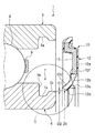
図1に示されるように、転がり軸受1は、固定輪である外輪5と、回転輪である内輪6と、外輪5と内輪6との間で保持器9により転動自在に保持されて周方向に等間隔に配設された複数の転動体である玉8と、外輪5および内輪6により画成された円環状隙間の開口部を密封する密封装置である接触型シール10を備えている。
As shown in FIG. 1, the rolling
接触型シール10は、芯金11と、シール材12と、から構成されている。芯金11は、例えば金属材料を円環状に形成した部材であり、その外表面に固着されるシール材12を補強している。シール材12は、ゴムなどの弾性体から形成されており、芯金11に固着された基部12aと、基部12aから延設され半径方向内方に向かうに従って次第に転がり軸受1の内部(図1において左方向)に向かって傾斜した首部12bと、首部12bの内径側周端部12dから転がり軸受1の内部に向かって突設された主リップ12cと、首部12bの内径側周端部12dから転がり軸受1の外部に向かって突設された副リップ12eと、を有している。
The contact-
外輪5および内輪6により画成された前記円環状隙間の開口部において、外輪5の内周面には円環状の固定溝5aが形成されており、固定溝5aには、接触型シール10の第1周端部であるシール材12の基部12aの外径側周端部が装着固定される。内輪6の外周面には、シール溝7が設けられており、転がり軸受1の内部側(図1においては左側)にあたるシール溝7の側部には、軸方向に略垂直とされた側壁面7bが形成されている。また、転がり軸受1の外部側(図1においては右側)にあたるシール溝7の側部には、側壁面7bの最大外径よりも小径とされた肩部7cが形成されている。
In the opening of the annular gap defined by the
シール材12の首部12bは、他の部位と比較して弾性変形し易いように、基部12aから半径方向内方に長く延びて形成されており、また、主リップ12cは適度の弾性と高い耐摩耗性を備え、内輪6の外周面に設けられたシール溝7の側壁面7bに摺接する。副リップ12eは、シール溝7の肩部7cの外周面と略同一の形状に形成されており、肩部7cの外周面に対向して配置されて肩部7cと協働してラビリンス効果を発揮するようになっている。
The
接触型シール10が単体の状態(即ち、転がり軸受1に非装着状態)のとき、シール材12の第2周端部である内径側周端部12dの最小内径D1は、シール溝7の肩部7cの外径D2より大きく設定されている。即ち、内径側周端部12dと肩部7cとの間には、隙間C1が設けられている。
When the contact-
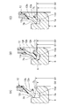
さらに図2を参照して、接触型シール10を転がり軸受1に装着する工程を説明する。図2(A)は接触型シール10の主リップ12cがシール溝7の側壁面7bに当接したときの状態を示し、図2(B)は接触型シール10が更に転がり軸受1の軸方向内部に押し込まれ、主リップ12cが側壁面7bを押圧し、その反力によりシール材12の首部12bが弾性変形した状態を示し、図2(C)は接触型シール10が完全に転がり軸受1に装着された状態を示す。
Furthermore, with reference to FIG. 2, the process of mounting the contact-
接触型シール10の転がり軸受1への装着固定は、転がり軸受1の前記開口部の側方(図1において右側)から接触型シール10を軸方向に移動させ、第1周端部であるシール材12の基部12aの外径側周端部を弾性変形させながら外輪5の固定溝5aに係合させて行う。
The contact-
図2(A)に示されるように、接触型シール10の軸方向の移動に伴って、シール材12の主リップ12cは肩部7cを通過して側壁面7bに当接する。このとき、シール材12の内径側周端部12dの最小内径D1は肩部7cの外径D2より大径とされているので、内径側周端部12dが肩部7cと干渉することがなく、よって、主リップ12cのめくれや、シール材12(特に、密封性に直接関係する内径側周端部12d、および内径側周端部12dに設けられた主リップ12c、副リップ12e)に傷や亀裂などの損傷を与えることが防止される。
As shown in FIG. 2A, as the contact-
次いで、図2(B)に示されるように、主リップ12cが側壁面7bに当接した後、さらに接触型シール10が転がり軸受1の内部方向(図3において左方向)に押し込まれると、主リップ12cが側壁面7bを押圧し、その反力により、主に首部12bが弾性変形する。即ち、転がり軸受1の内部に向かって傾斜していた首部12bは、芯金11との接合部12f近傍(即ち、基部12aと首部12bとの断面形状の変化が大きい部分)を支点として転がり軸受1の外部に向かう方向(図中、矢印A方向)に旋回して半径方向に略平行となるように、その傾斜を矯正される。このとき、内径側周端部12dの最小内径D1は次第に小さくなる。
Next, as shown in FIG. 2 (B), after the
そして、図2(C)に示されるように、接触型シール10の装着完了時には、内径側周端部12dの最小内径D1は肩部7cの外径D2よりも小さく若しくは等しくなり、内径側周端部12dは、シール溝7内部に進入して肩部7cと軸方向に重畳(オーバーラップ)する。
As shown in FIG. 2C, when the contact-
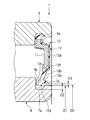
図3に示すように、接触型シール10の装着完了後は、主リップ12cと側壁面7bが密着して転がり軸受1を密封すると共に、内径側周端部12dの最小内径D1が肩部7cの外径D2よりも小径となることにより、内径側周端部12dとシール溝7の周面7aとの隙間C2および副リップ部12eと肩部7cとの隙間C3が、ラビリンス効果を有効に発揮する程度に小さくなっている。
As shown in FIG. 3, after the contact-
上述した転がり軸受1によれば、円環状の芯金11によりシール材12を補強してなる接触型シール10を備え、非装着時におけるシール材12の内径側周端部12dの最小内径D1がシール溝7の肩部7cの外径D2より大きく設定されているので、接触型シール10の転がり軸受1への装着作業時に、内径側周端部12dと肩部7aとが干渉することなく、接触型シール10を転がり軸受1にスムーズに装着固定することができる。そして、主リップ12cのめくれや、シール材12(特に、密封性に直接関係する主リップ12c、副リップ12e、内径側周端部12d)に傷や亀裂などの損傷を与えることを防止することができる。さらに、装着完了時におけるシール材12の内径側周端部12dの最小内径D1がシール溝7の肩部7cの外径D2より小さくなり、内径側周端部12dとシール溝7の周面7aとの隙間C2および副リップ部12eと肩部7cとの隙間C3が、ラビリンス効果を有効に発揮する程度に小さくなるので、接触型シール10による密封性能を向上させることができる。これにより、接触型シール10に損傷を与えることなく転がり軸受1に極めて容易に装着することができ、且つ優れた密封性能を有する接触型シール10を備えた転がり軸受1を提供することができる。
According to the rolling
尚、本発明は、前述した実施形態に限定されるものではなく、適宜、変形、改良、等が可能である。その他、前述した実施形態における各構成要素の材質、形状、寸法、数値、形態、数、配置箇所、等は本発明を達成できるものであれば任意であり、限定されない。 In addition, this invention is not limited to embodiment mentioned above, A deformation | transformation, improvement, etc. are possible suitably. In addition, the material, shape, dimension, numerical value, form, number, arrangement location, and the like of each component in the above-described embodiment are arbitrary and are not limited as long as the present invention can be achieved.
例えば、前述した実施形態では、接触型シールは外輪に固定され、主リップが内輪のシール溝に摺接するようにしたが、本発明はこれに限定されず、接触型シールを内輪に固定して主リップが外輪に形成されたシール溝と摺接する配置としてもよい。この場合、シール材の首部は芯金に固着された基部から半径方向外方に向かって延設される。そして、接触型シールのシール材の外径側周端部(即ち、第2周端部)の最大外径が、転がり軸受への非装着時には外輪の内周面に形成されたシール溝の肩部の内径よりも小さく設定され、装着完了時には前記肩部の内径より大きくなって外輪との隙間を小さくする。また、前述した実施形態では、外輪を固定輪とし且つ内輪を回転輪として説明したが、外輪を回転輪とし且つ内輪を固定輪としてもよい。 For example, in the above-described embodiment, the contact type seal is fixed to the outer ring and the main lip is slidably contacted with the seal groove of the inner ring, but the present invention is not limited to this, and the contact type seal is fixed to the inner ring. The main lip may be disposed so as to be in sliding contact with a seal groove formed in the outer ring. In this case, the neck of the sealing material extends radially outward from the base fixed to the cored bar. The maximum outer diameter of the outer diameter side peripheral end portion (that is, the second peripheral end portion) of the seal material of the contact seal is the shoulder of the seal groove formed on the inner peripheral surface of the outer ring when not attached to the rolling bearing. It is set smaller than the inner diameter of the portion, and when the mounting is completed, it becomes larger than the inner diameter of the shoulder portion to reduce the gap with the outer ring. In the above-described embodiment, the outer ring is a fixed ring and the inner ring is a rotating ring. However, the outer ring may be a rotating ring and the inner ring may be a fixed ring.
また、前述した実施形態では、主にシール材の首部が弾性変形することによって、シール材の内径側周端部の最小内径を小さくするようにしたが、第2周端部とシール溝の周面との隙間を小さくする方向に作用するものであれば、弾性変形する箇所を首部に限定する必要はなく、例えば、首部と主リップとの連結部分で旋回させるようにしてもよい。 In the above-described embodiment, the minimum inner diameter of the inner circumferential side end of the sealing material is reduced mainly by elastic deformation of the neck of the sealing material. As long as it acts in the direction of reducing the gap with the surface, it is not necessary to limit the elastically deformed portion to the neck portion. For example, the portion may be turned at the connecting portion between the neck portion and the main lip.
1 転がり軸受
5 外輪(固定輪)
6 内輪(回転輪)
7 シール溝
7a 周面
7b 側壁面
7c 肩部
8 玉(転動体)
10 接触型シール(密封装置)
11 芯金
12 シール材
12a 基部
12b 首部
12c 主リップ
12d 内径部
D1 内径部の最小内径
D2 肩部外径
1 Rolling bearing 5 Outer ring (fixed ring)
6 Inner ring (rotating wheel)
7
10 Contact type seal (sealing device)
11
Claims (2)
前記固定輪および前記回転輪のうち一方に装着固定される第1周端部と、前記固定輪および前期回転輪のうち他方に形成されたシール溝に摺接する第2周端部と、を有する円環状の密封装置をさらに備え、
前記密封装置の第2周端部が、前記密封装置の装着時には前記シール溝の肩部と干渉しない径とされており、且つ前記密封装置の装着完了時には前記シール溝の肩部と軸方向に重畳する径となることを特徴とする転がり軸受。 A rolling bearing comprising a fixed wheel, a rotating wheel, and a plurality of rolling elements arranged to freely roll in the circumferential direction between the fixed wheel and the rotating wheel,
A first peripheral end portion mounted and fixed to one of the fixed wheel and the rotating wheel; and a second peripheral end portion slidably contacting a seal groove formed on the other of the fixed wheel and the previous rotating wheel. Further comprising an annular sealing device;
The second peripheral end of the sealing device has a diameter that does not interfere with the shoulder of the seal groove when the sealing device is mounted, and extends axially with the shoulder of the seal groove when the sealing device is mounted. Rolling bearings characterized by overlapping diameters.
Priority Applications (1)
| Application Number | Priority Date | Filing Date | Title |
|---|---|---|---|
| JP2004112767A JP2005299716A (en) | 2004-04-07 | 2004-04-07 | Rolling bearing |
Applications Claiming Priority (1)
| Application Number | Priority Date | Filing Date | Title |
|---|---|---|---|
| JP2004112767A JP2005299716A (en) | 2004-04-07 | 2004-04-07 | Rolling bearing |
Publications (1)
| Publication Number | Publication Date |
|---|---|
| JP2005299716A true JP2005299716A (en) | 2005-10-27 |
Family
ID=35331499
Family Applications (1)
| Application Number | Title | Priority Date | Filing Date |
|---|---|---|---|
| JP2004112767A Pending JP2005299716A (en) | 2004-04-07 | 2004-04-07 | Rolling bearing |
Country Status (1)
| Country | Link |
|---|---|
| JP (1) | JP2005299716A (en) |
Cited By (3)
| Publication number | Priority date | Publication date | Assignee | Title |
|---|---|---|---|---|
| JP2008185112A (en) * | 2007-01-29 | 2008-08-14 | Nsk Ltd | Ball bearing and support structure |
| US8292512B2 (en) | 2007-01-29 | 2012-10-23 | Nsk Ltd. | Ball bearing and supporting construction |
| WO2019138938A1 (en) * | 2018-01-09 | 2019-07-18 | Ntn株式会社 | Rolling bearing and method for designing same |
-
2004
- 2004-04-07 JP JP2004112767A patent/JP2005299716A/en active Pending
Cited By (5)
| Publication number | Priority date | Publication date | Assignee | Title |
|---|---|---|---|---|
| JP2008185112A (en) * | 2007-01-29 | 2008-08-14 | Nsk Ltd | Ball bearing and support structure |
| US8292512B2 (en) | 2007-01-29 | 2012-10-23 | Nsk Ltd. | Ball bearing and supporting construction |
| WO2019138938A1 (en) * | 2018-01-09 | 2019-07-18 | Ntn株式会社 | Rolling bearing and method for designing same |
| JP2019120354A (en) * | 2018-01-09 | 2019-07-22 | Ntn株式会社 | Roll bearing and its design method |
| JP7137310B2 (en) | 2018-01-09 | 2022-09-14 | Ntn株式会社 | Rolling bearing and its design method |
Similar Documents
| Publication | Publication Date | Title |
|---|---|---|
| JP3740219B2 (en) | Rolling bearing sealing device | |
| JP7207484B2 (en) | rolling bearing | |
| WO2017204058A1 (en) | Bearing sealing device | |
| JP2010190241A (en) | Self-aligning roller bearing | |
| JP2013242033A (en) | Rolling bearing | |
| JP5235392B2 (en) | Double row angular contact ball bearings | |
| JP2006316884A (en) | Bearing with sealing device | |
| JP2018119681A (en) | Rotary machine seal structure, rotary machine and seal member | |
| JP2010002017A (en) | Rolling bearing | |
| JP4822173B2 (en) | Hub unit for vehicles | |
| JP2005299716A (en) | Rolling bearing | |
| JP6953264B2 (en) | Sealed structure | |
| JP5781318B2 (en) | Slewing bearing seal structure | |
| JP2008025600A (en) | Sealing device for bearing | |
| JP4531541B2 (en) | Sealing device | |
| JP6981143B2 (en) | Ball bearing with seal | |
| JP2009074589A (en) | Sealing device | |
| JP2005325867A (en) | Bearing for railroad car | |
| JP2008223996A (en) | Rolling bearing sealing device | |
| JP5365346B2 (en) | Sealing device, sealing structure and rolling bearing | |
| JP7015656B2 (en) | Sealing device | |
| JP2004316853A (en) | Bearing device for railway vehicles | |
| JP2003049853A (en) | Seal structure of bearing device for vehicle | |
| JP2014177954A (en) | Sealing device and rolling bearing unit equipped therewith | |
| JP4428719B2 (en) | Rolling bearing sealing device |
Legal Events
| Date | Code | Title | Description |
|---|---|---|---|
| RD04 | Notification of resignation of power of attorney |
Free format text: JAPANESE INTERMEDIATE CODE: A7424 Effective date: 20060327 |