JP2005299640A - Valve timing control device for internal combustion engine - Google Patents
Valve timing control device for internal combustion engine Download PDFInfo
- Publication number
- JP2005299640A JP2005299640A JP2005036151A JP2005036151A JP2005299640A JP 2005299640 A JP2005299640 A JP 2005299640A JP 2005036151 A JP2005036151 A JP 2005036151A JP 2005036151 A JP2005036151 A JP 2005036151A JP 2005299640 A JP2005299640 A JP 2005299640A
- Authority
- JP
- Japan
- Prior art keywords
- rotation
- valve timing
- rotational
- rotational phase
- camshaft
- Prior art date
- Legal status (The legal status is an assumption and is not a legal conclusion. Google has not performed a legal analysis and makes no representation as to the accuracy of the status listed.)
- Pending
Links
Images


Classifications
-
- Y02T10/18—
Landscapes
- Output Control And Ontrol Of Special Type Engine (AREA)
- Valve Device For Special Equipments (AREA)
Abstract
【課題】低回転時においても、高応答・高精度なバルブタイミング制御を行う。
【解決手段】クランク角センサ及びカムセンサの出力信号に基づいて、カムシャフトの回転周期毎にクランクシャフトに対するカムシャフトの回転位相を検出できる第1回転位相検出手段と、カムシャフトの回転周期にかかわらず前記回転位相を任意のタイミングで検出できる第2回転位相検出手段と、を備え、機関回転速度Neが所定回転速度Ns2以下のときは、第2回転位相検出手段により検出した回転位相θdet2に基づいて可変バルブタイミング機構のフィードバック操作量を算出する(S24、S26)。一方、機関回転速度が所定回転速度Ns2を上回るときは、第1回転位相検出手段により検出した回転位相θdet1に基づいて可変バルブタイミング機構のフィードバック操作量を算出する(S25、S26)。
【選択図】 図18Highly responsive and highly accurate valve timing control is performed even at low speeds.
First rotation phase detection means capable of detecting a rotation phase of a camshaft with respect to a crankshaft at every rotation cycle of the camshaft based on output signals of a crank angle sensor and a cam sensor, and irrespective of the rotation cycle of the camshaft Second rotational phase detecting means capable of detecting the rotational phase at an arbitrary timing, and when the engine rotational speed Ne is equal to or lower than a predetermined rotational speed Ns2, based on the rotational phase θdet2 detected by the second rotational phase detecting means. A feedback operation amount of the variable valve timing mechanism is calculated (S24, S26). On the other hand, when the engine rotation speed exceeds the predetermined rotation speed Ns2, the feedback operation amount of the variable valve timing mechanism is calculated based on the rotation phase θdet1 detected by the first rotation phase detection means (S25, S26).
[Selection] FIG.
Description
本発明は、内燃機関のクランクシャフトに対するカムシャフトの回転位相を変化させることで、機関の吸気バルブ又は排気バルブのバルブタイミング(開閉タイミング)を変化させる内燃機関のバルブタイミング制御装置に関する。 The present invention relates to a valve timing control device for an internal combustion engine that changes a valve timing (opening / closing timing) of an intake valve or an exhaust valve of the engine by changing a rotational phase of a camshaft with respect to a crankshaft of the internal combustion engine.
特許文献1に開示されているように、従来の内燃機関のバルブタイミング制御装置においては、クランクシャフトの基準回転位置でクランク角信号を出力するクランク角センサと、カムシャフトの基準回転位置でカム信号を出力するカムセンサと、を備え、その基準回転位置のずれ角に基づいて、クランクシャフトに対するカムシャフトの回転位相を検出していた。
ところで、上記従来の構成のもとでは、一定のクランク角(カムシャフトの回転周期)毎に回転位相が検出されることになるが、かかる回転位相の検出結果に基づく可変バルブタイミング機構のフィードバック制御(バルブタイミング制御)は、一般に微少単位時間毎に実行される。
このため、特に低回転時においては、フィードバック制御の実行周期よりも回転位相の検出周期の方が長くなってしまい、制御上十分な頻度で回転位相を検出できない。このような場合には、実際とは異なる回転位相に基づいて目標回転位相との偏差が算出され、誤った偏差に基づいてフィードバック操作量が算出されることになって、制御性が悪化してしまうという問題があった。
By the way, under the above-described conventional configuration, the rotation phase is detected at every constant crank angle (camshaft rotation cycle), and feedback control of the variable valve timing mechanism based on the detection result of the rotation phase. (Valve timing control) is generally executed every minute unit time.
For this reason, especially at the time of low rotation, the rotation phase detection cycle becomes longer than the feedback control execution cycle, and the rotation phase cannot be detected with sufficient frequency in terms of control. In such a case, the deviation from the target rotational phase is calculated based on the rotational phase different from the actual one, and the feedback manipulated variable is calculated based on the erroneous deviation, resulting in poor controllability. There was a problem that.
本発明は、このような課題に着目してなされたものであり、カムシャフトの回転周期とは無関係に、任意のタイミングで回転位相を検出することで、低回転時であっても高応答・高精度なバルブタイミング制御を実現することを目的とする。 The present invention has been made paying attention to such a problem, and by detecting the rotation phase at an arbitrary timing regardless of the rotation period of the camshaft, the high response and The purpose is to realize highly accurate valve timing control.
このため、請求項1に記載の発明は、内燃機関のクランクシャフトに対するカムシャフトの回転位相を変化させることで、吸気バルブ又は排気バルブの開閉タイミングを変化させる可変バルブタイミング機構を備えた構成において、前記回転位相を任意のタイミングで検出できる回転位相検出手段を備え、この回転位相検出手段により検出した回転位相に基づいて前記可変バルブタイミング機構を制御する。
For this reason, the invention according to
このようにすると、機関回転とは無関係に(より具体的には、カムシャフトの回転周期よりも短い周期であっても)回転位相を検出できるので、バルブタイミング制御(フィードバック制御)を行うに際し、低回転時であってもバルブタイミングの制御周期と回転位相の検出周期とを一致させて、高応答、高精度のバルブタイミング制御を実現できる。
請求項2に記載の発明は、前記回転位相検出手段が前記カムシャフトの回転周期にかかわらず、前記回転位相を直接検出する。
In this way, the rotational phase can be detected regardless of the engine rotation (more specifically, even if the rotation period is shorter than the rotation period of the camshaft). Therefore, when performing valve timing control (feedback control), Even at the time of low rotation, the valve timing control cycle and the rotation phase detection cycle are made to coincide with each other, thereby realizing a highly responsive and highly accurate valve timing control.
According to a second aspect of the present invention, the rotational phase detecting means directly detects the rotational phase regardless of the rotational period of the camshaft.
このようにすると、クランクシャフトの回転位置(角度)とカムシャフトの回転位置(角度)とのそれぞれを検出する必要がなく、一つの検出値(出力信号)に基づくバルブタイミング制御が可能となる。
請求項3に記載の発明は、内燃機関のクランクシャフトに対するカムシャフトの回転位相を変化させることで、吸気バルブ又は排気バルブの開閉タイミングを変化させる可変バルブタイミング機構を備えた構成において、前記クランクシャフトの基準回転位置を検出するクランク角センサ及びカムシャフトの基準回転位置を検出するカムセンサの出力信号に基づいて、カムシャフトの回転周期毎に前記回転位相を検出する第1回転位相検出手段と、カムシャフトの回転周期にかかわらず、前記回転位相を任意のタイミングで検出できる第2回転位相検出手段とを備え、機関回転速度が所定回転速度以下のときは、前記第2回転位相検出手段によって検出した回転位相に基づいて前記可変バルブタイミング機構を制御し、機関回転速度が所定回転速度を上回るときは、前記第1回転位相検出手段によって検出した回転位相に基づいて前記可変バルブタイミング機構を制御する。
In this way, it is not necessary to detect the rotational position (angle) of the crankshaft and the rotational position (angle) of the camshaft, and valve timing control based on one detection value (output signal) becomes possible.
According to a third aspect of the present invention, there is provided a variable valve timing mechanism for changing an opening / closing timing of an intake valve or an exhaust valve by changing a rotational phase of a camshaft with respect to a crankshaft of an internal combustion engine. A first rotation phase detection means for detecting the rotation phase for each rotation period of the camshaft based on an output signal of a crank angle sensor for detecting the reference rotation position of the camshaft and a cam sensor for detecting the reference rotation position of the camshaft; A second rotational phase detecting means capable of detecting the rotational phase at an arbitrary timing regardless of the rotational period of the shaft, and when the engine rotational speed is equal to or lower than a predetermined rotational speed, the second rotational phase detecting means detects the rotational phase. Based on the rotational phase, the variable valve timing mechanism is controlled so that the engine rotational speed is a predetermined number of times. When exceeding the speed, controls the variable valve timing mechanism based on the rotation phase detected by said first rotational phase detecting means.
請求項4に記載の発明は、前記第2回転位相検出手段が前記回転位相を直接検出する。
請求項5に記載の発明は、前記第1回転位相検出手段による回転位相検出周期(カムシャフトの回転周期)が可変バルブタイミング機構の制御周期よりも長くなるときは、前記第2回転位相検出手段によって検出した回転位相に基づいて可変バルブタイミング機構を制御し、それ以外のときは、第1回転位相検出手段によって検出した回転位相に基づいて可変バルブタイミング機構を制御する。
According to a fourth aspect of the present invention, the second rotational phase detection means directly detects the rotational phase.
According to a fifth aspect of the present invention, when the rotation phase detection period (camshaft rotation period) by the first rotation phase detection means is longer than the control period of the variable valve timing mechanism, the second rotation phase detection means The variable valve timing mechanism is controlled based on the rotational phase detected by the first rotational phase detection means. Otherwise, the variable valve timing mechanism is controlled based on the rotational phase detected by the first rotational phase detection means.
以上の請求項3〜4に記載の発明によると、低回転時であって実際の回転位相と制御に用いる回転位相との「ずれ」が大きくなり易いときには、第2回転位相検出手段により回転位相を検出する一方、前記「ずれ」がそれほど問題とならない(大きくならない)ときには、第1回転位相検出手段により回転位相を検出し、この検出した回転位相に基づいてバルブタイミング制御が実行される。これにより、従来から安定している第1回転位相検出手段により検出される回転位相に基づくバルブタイミング制御を最大限利用しつつ、低回転時におけるバルブタイミング制御の制御性の向上させることができる。なお、第2回転位相検出手段が回転位相を直接検出することにより、請求項2に記載の発明と同様、クランクシャフトの回転位置(角度)とカムシャフトの回転位置(角度)とのそれぞれを検出する必要がなく、一つの検出値(出力信号)に基づくバルブタイミング制御が可能となる。 According to the third to fourth aspects of the present invention, when the "rotation" between the actual rotational phase and the rotational phase used for control is likely to be large even at a low rotational speed, the rotational phase is detected by the second rotational phase detecting means. On the other hand, when the “deviation” does not become a significant problem (does not increase), the rotational phase is detected by the first rotational phase detection means, and the valve timing control is executed based on the detected rotational phase. Thereby, it is possible to improve the controllability of the valve timing control at the time of low rotation, while making maximum use of the valve timing control based on the rotation phase detected by the first rotation phase detecting means that has been conventionally stable. The second rotational phase detecting means directly detects the rotational phase to detect the rotational position (angle) of the crankshaft and the rotational position (angle) of the camshaft as in the second aspect of the invention. Therefore, valve timing control based on one detection value (output signal) is possible.
請求項6に記載の発明は、低回転領域において、機関回転速度が低い(小さい)ほど大きく設定される制御ゲインを用いて前記可変バルブタイミング機構のフィードバック操作量を算出する。
このようにすると、低回転時は可変バルブタイミング機構における摺動抵抗が増加して制御応答性が低下することになるが、この低下分を補うようにフィードバック制御ゲインが設定することができるので、低回転時における応答性を更に向上させることができる。
The invention according to claim 6 calculates the feedback manipulated variable of the variable valve timing mechanism using a control gain that is set larger as the engine rotational speed is lower (smaller) in the low speed region.
If this is done, the sliding resistance in the variable valve timing mechanism will increase at the time of low rotation and the control responsiveness will decrease, but the feedback control gain can be set to compensate for this decrease, Responsiveness at the time of low rotation can be further improved.
以下、本発明の実施の形態を図に基づいて説明する。
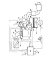
図1は、実施形態における車両用内燃機関の構成図である。この図1において、内燃機関101の吸気管102には、スロットルモータ103aでスロットルバルブ103bを開閉駆動する電子制御スロットル104が介装され、該電子制御スロットル104及び吸気バルブ105を介して、燃焼室106内に空気が吸入される。
Hereinafter, embodiments of the present invention will be described with reference to the drawings.
FIG. 1 is a configuration diagram of an internal combustion engine for a vehicle in the embodiment. In FIG. 1, an
機関の各燃焼室には点火プラグ133が設けられており、これにより火花点火して混合気を着火燃焼させる。燃焼排気は燃焼室106から排気バルブ107を介して排出され、フロント触媒108及びリア触媒109で浄化された後、大気中に放出される。
前記吸気バルブ105及び排気バルブ107は、それぞれ吸気側カムシャフト134、排気側カムシャフト110に設けられたカムによって開閉駆動されるが、吸気側カムシャフト134には、可変バルブタイミング機構(VTC)113が設けられている。
Each combustion chamber of the engine is provided with a
The
このVTC113は、クランクシャフト120に対する吸気側カムシャフト134の回転位相を変化させることで吸気バルブ105の開閉タイミングを変化させる機構であるが、その詳細については後述する。
なお、本実施形態では吸気バルブ105側にのみVTC113を備える構成としたが、吸気バルブ105側に代えて又は吸気バルブ105側と共に、排気バルブ107側にVTC113を備える構成であっても良い。
The
In the present embodiment, the
また、各気筒の吸気ポート130には、電磁式の燃料噴射弁131が設けられ、該燃料噴射弁131は、エンジンコントロールユニット(ECU)114からの噴射パルス信号によって開弁駆動されると、所定圧力に調整された燃料を吸気バルブ105に向けて噴射する。
マイクロコンピュータを内蔵するECU114には、各種センサからの検出信号(出力信号)が入力され、該信号に基づく演算処理によって、前記電子制御スロットル104、VTC113及び燃料噴射弁131を制御する。
In addition, an electromagnetic
Detection signals (output signals) from various sensors are input to the
前記各種センサとしては、アクセル開度を検出するアクセル開度センサAPS116、機関101の吸入空気量Qaを検出するエアフローメータ115、クランクシャフト120からクランク角180°毎の基準回転位置で基準クランク角信号REFを取り出すと共に単位クランク角度毎の単位角度信号POSを取り出すクランク角センサ117、スロットルバルブ103bの開度TVOを検出するスロットルセンサ118、機関101の冷却水温度Twを検出する水温センサ119、吸気側カムシャフト134からカム角90°(クランク角180°)毎の基準回転位置でカム信号CAMを取り出すカムセンサ132、燃焼室106内の燃焼圧力を検出する圧力センサ135、バッテリ電圧Vbを検出する電圧センサ136等が設けられている。なお、機関回転速度Neは、前記基準クランク角信号REFの周期、又は、単位時間当たりの単位角度信号POSの発生数に基づいて算出される。
Examples of the various sensors include an accelerator opening sensor APS116 for detecting the accelerator opening, an
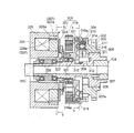
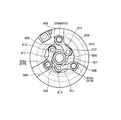
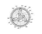
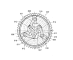
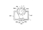
次に、前記VTC113の構成を、図2〜図9に基づいて説明する。図2に示すように、本実施形態に係るVTC113は、前記吸気側カムシャフト(以下、単にカムシャフトという)134と、このカムシャフト134の前端部に相対回動できるように組み付けられ、タイミングチェーン(図示せず)を介してクランクシャフト120に連係されるタイミングスプロケット302(駆動回転体)と、このタイミングスプロケット302とカムシャフト134の前方側(図2において左側)に配置されて、カムシャフト134とタイミングスプロケット302との組付角を操作する組付角操作機構304と、この組付角操作機構304のさらに前方側に配置されて、同機構304を駆動する操作力付与手段305と、内燃機関の図外のシリンダヘッドとヘッドカバーの前面に跨って取り付けられて組付角操作機構304と操作力付与手段305の前面と周域を覆う図外のVTCカバーと、を備えている。なお、図3(及び図5)は図2のA−A断面に相当し、図4は図2のB−B断面に相当する。
Next, the configuration of the
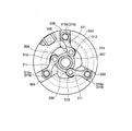
タイミングスプロケット302は、段差状の挿通孔306を備えた短軸円筒状に形成され、外周には前記タイミングチェーンと噛み合う歯車部303を有している。そして、前記挿通孔306部分が、カムシャフト134の前端部に結合された従動軸部材307(従動回転体)に回転可能に組み付けられている。また、タイミングスプロケット302の前面(カムシャフト134と逆側の面)には、図3に示すように、対面する平行な側壁を有する3個の径方向溝308(径方向ガイド)がタイミングスプロケット302のほぼ半径方向に沿うように形成されている。
The timing sprocket 302 is formed in a short shaft cylindrical shape having a step-
従動軸部材307は、図2に示すように、軸芯部を貫通するボルト310によってカムシャフト134に結合されている。また、カムシャフト134の前端部に突き合される基部側外周に拡径部307aが形成されると共に、その拡径部よりも前方側の外周面に放射状に突出する三つのレバー(突起部)309が一体に形成されている。
各突起部309には、三つのリンク311の基端がピン312によって回転可能に連結される。前記各リンク311の先端には、前記各径方向溝308に摺動自由に係合する円柱状の突出部313が一体に形成されている。
As shown in FIG. 2, the driven
The base ends of the three
前記各リンク311は、各突出部313が対応する径方向溝308に係合した状態において、ピン312を介して従動軸部材307に連結されているため、リンク311の先端側が外力を受けて径方向溝308に沿って変位すると、タイミングスプロケット302と従動軸部材307とは、リンク311の作用によって相対回動する。
また、各リンク311の先端部には、軸方向前方側に開口する収容穴314が形成されている。この収容穴314には、後述する渦巻き溝315(渦巻き状ガイド)に係合する球面突起316aを有する係合ピン316(転動部材)と、この係合ピン316を前方側(渦巻き溝315側)に付勢するコイルばね317とが収容されている。
Each
In addition, a housing hole 314 that opens to the front side in the axial direction is formed at the tip of each
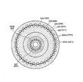
一方、従動軸部材307の突起部309よりも前方側には、フランジ部318aを有する円板状の中間回転体318が、軸受329を介して回転自在に支持されている。
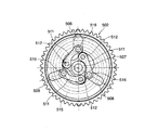
この中間回転体318の後方側(カムシャフト134側)には、断面半円状の前述の渦巻き溝315が形成され、この渦巻き溝315に、前記各リンク311の先端の係合ピン316が転動自在に係合されている。
On the other hand, a disk-shaped intermediate
The above-described
渦巻き溝315は、タイミングスプロケット302の回転方向に沿って次第に縮径するように形成されている。
従って、各リンク311の先端の係合ピン316が渦巻き溝315に係合した状態において、中間回転体318がタイミングスプロケット302に対して遅れ方向に相対回転すると、各リンク311の先端部は、径方向溝308に案内されつつ、渦巻き溝315の渦巻き形状に誘導されて半径方向内側に移動する。逆に、中間回転体318が進み方向に相対変位すると、半径方向外側に移動する。
The
Therefore, when the intermediate
前記組付角操作機構304は、前記タイミングスプロケット302の径方向溝308、リンク311、突出部313、係合ピン316、突起部309、中間回転体318、渦巻き溝315等によって構成されている。
そして、前記操作力付与手段305から中間回転体318に対して回動操作力が入力されると、渦巻き溝315と係合ピン316との係合部を通して、リンク311の先端を径方向に変位させ、リンク311と突起部309との作用によって、タイミングスプロケット302と従動軸部材307(従って、カムシャフト134)との組付角を変化させる回動力として伝達する。
The assembly
When a turning operation force is input from the operation force applying means 305 to the intermediate
操作力付与手段305は、中間回転体318をタイミングスプロケット302の回転方向に付勢するゼンマイばね319と、中間回転体318をタイミングスプロケット302の回転方向とは逆方向に回動させる制動力を発生するヒステリシスブレーキ320と、を備えている。そして、ECU114が、内燃機関101の運転状態に応じてヒステリシスブレーキ320の制動力を制御することにより、中間回転体318をタイミングスプロケット302に対して相対回転させ、その回転位置を維持できるようになっている。
The operating force applying means 305 generates a
ゼンマイばね319は、タイミングスプロケット302に一体に取り付けられた円筒部材321にその外周端部が結合される一方で、内周端部が中間回転体318の円筒状の基部に結合され、全体が中間回転体318のフランジ壁318aの前方側スペースに配置されている。
ヒステリシスブレーキ320は、中間回転体318の前端部にリテーナプレート322を介して取り付けられた有底円筒状のヒステリシスリング323と、非回転部材である図外のVTCカバーに回転を規制した状態で取り付けられた磁界制御手段としての電磁コイル324と、電磁コイル324の磁気を誘導する磁気誘導部材であるコイルヨーク325と、を備える。そして、ECU114が、内燃機関101の運転状態に応じて前記電磁コイル324への通電を制御する。具体的には、ECU114は、電磁コイル324に対する通電量を、ディザ信号が重畳されたデューティ制御信号に基づいて制御する。
The
The
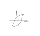
ヒステリシスリング323は、図6に示すように、外部の磁界の変化に対して位相遅れをもって磁束力が変化する特性(磁気的ヒステリシス特性)を持つヒステリシス材(半硬質材)によって形成され、外周側の円筒部(壁)323aが前記コイルヨーク325によって制動作用を受けるようになっている。
コイルヨーク325は、電磁コイル324を取り囲むように全体が略円筒形状に形成され、その外周面が図外のシリンダヘッドに固定されている。また、コイルヨーク325の内周面は、軸受328を介して従動軸部材307の先端部に回転可能に支持されている。
As shown in FIG. 6, the
The
そして、コイルヨーク315の後部面側(中間回転体318側)には、所定の隙間を有して向かい合う一対の対向面326、327が形成されている。
コイルヨーク325の両対向面326、327には、図4に示すように、夫々円周方向に沿って複数の凹凸が連続して形成され、これらの凹凸のうち凸部326a、327aが磁極(磁界発生部)を構成している。
A pair of facing
As shown in FIG. 4, a plurality of concavities and convexities are continuously formed on the opposing
そして、一方の対向面326の凸部326aと他方の対向面327の凸部327aとは円周方向に交互に配置され、対向面326、327相互の近接する凸部326a,327aがすべて円周方向にずれている。
従って、両対向面326、327の近接する凸部326a、327a間には、電磁コイル24の励磁によって円周方向に傾きをもった向きの磁界が発生する(図7参照)。なお、前記ヒステリシスリング323の円筒部(壁)323aは、両対向面326、327間の隙間に非接触状態で介装されている。
And the
Therefore, a magnetic field having a direction inclined in the circumferential direction is generated between the adjacent
ここで、このヒステリシスブレーキ320の作動原理を図8により説明する。図8(a)はヒステリシスリング323(ヒステリシス材)に最初に磁界をかけた状態を示し、図8(b)は上記(a)の状態からヒステリシスリング323を変位(回転)させた状態を示す。
図8(a)の状態においては、コイルヨーク325の両対向面326、327間における磁界の向き(対向面327の凸部327aから他方の対向面326の凸部326aに向かう磁界の向き)に沿うようにヒステリシスリング323内に磁束の流れが生じる。
Here, the operating principle of the
In the state of FIG. 8A, the direction of the magnetic field between the opposing
この状態からヒステリシスリング323が、外力F1を受けて図8(b)に示す状態に移動すると、外部磁界内をヒステリシスリング323が変位することとなるため、このときヒステリシスリング323の内部の磁束は位相遅れをもち、ヒステリシスリング323内部の磁束の向きは、対向面326、327間の磁界の向きに対してずれる(傾斜する)こととなる。
When the
従って、対向面327の凸部327aからヒステリシスリング323に入る磁束の流れ(磁力線)と、ヒステリシスリング323から他方の対向面326の凸部326aに向かう磁束の流れ(磁力線)が歪められ、このとき、この磁束の流れの歪みを矯正するような引き合い力が対向面326、327とヒステリシスリング323との間に作用し、その引き合い力がヒステリシスリング323を制動する抗力F2として働く。
Accordingly, the flow of magnetic flux (magnetic lines) entering the
つまり、ヒステリシスブレーキ320は、以上説明したように、ヒステリシスリング323が対向面326、327間の磁界内を変位するときに、ヒステリシスリング323内部の磁束の向きと磁界の向きのずれによって制動力を発生するものである。そして、その制動力は、ヒステリシスリング323の回転速度(対向面326、327とヒステリシスリング323の相対速度)に関係なく、磁界の強さ、即ち、電磁コイル324の励磁電流の大きさに略比例した一定の値となる。
That is, as described above, when the
なお、図9は、ヒステリシスブレーキ320における回転速度と制動トルクの関係を、励磁電流をa〜d(a<b<c<d)に変化させて調べた試験結果である。この試験結果から明らかなように、このヒステリシスブレーキ320よれば、回転速度の影響を受けることがなく、常に励磁電流値に応じた制動力を得ることができる。
本実施形態に係るVTC113は以上のような構成となっており、機関回転中(例えば、停止前のアイドル運転中)にヒステリシスブレーキ320の電磁コイル324の励磁がオフされると、ゼンマイばね319の力によって中間回転体318がタイミングスプロケット302に対して機関回転方向に最大に回転される(図3参照)。これにより、クランクシャフト120に対するカムシャフト134の回転位相はバルブタイミングが最も遅れる最遅角側(吸気バルブ105のバルブタイミングは最遅角タイミング)に維持される。
FIG. 9 shows test results obtained by examining the relationship between the rotational speed and the braking torque in the
The
この状態から前記回転位相を最進角側に変更すべき指令が前記ECU114から発されると、ヒステリシスブレーキ320の電磁コイル324の励磁がオンにされて、ゼンマイばね319の力に抗する制動力が中間回転体318に付与される。これにより、中間回転体318がタイミングスプロケット302に対して回転移動し、それによってリンク311の先端の係合ピン316が渦巻き溝315に誘導されてリンク311の先端部が径方向溝308に沿って変位し、図5に示すように、リンク311の作用によってタイミングスプロケット302と従動軸部材307の組付角が最進角側に変更される。この結果、回転位相はバルブタイミングが最も進む最進角側(吸気バルブ105のバルブタイミングは最進角タイミング)に変更される
一方、この状態(最進角側)から前記回転位相を最遅角側に変更すべき指令が前記ECU114から発されると、ヒステリシスブレーキ320の電磁コイル324の励磁がオフにされ、再度ゼンマイばね319の力によって中間回転体318が戻す方向に回転移動する。すると、渦巻き溝315による係合ピン316の誘導によってリンク311が上記と逆方向に揺動し、図3に示すように、そのリンク311の作用によってタイミングスプロケット302と従動軸部材307の組付角が再度最遅角側に変更される。
When the
なお、このVTC113によって変更される(クランクシャフトに対するカムシャフト134の)回転位相は、以上説明した最遅角と最進角の二種の位相ばかりでなく、ヒステリシスブレーキ320の制動力の制御によって任意の位相に変更することができ、ゼンマイばね319の力とヒステリシスブレーキ320の制動力のバランスによってその位相を保持することもできる。
Note that the rotational phase (of the
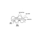
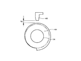
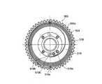
また、本実施形態に係るVTC113は、図10に示すように、カムシャフト134と共に回転する回転体401と、この回転体401の外周に近接配置された電磁式のギャップセンサ402とを備えている。
回転体401は直接又は他の部材を介して間接的にカムシャフト134に固定されており、その外周は、図10に示すように、カムシャフト134の中心からの距離が周方向で徐々に変化するよう形成されている。ギャップセンサ402は、カムシャフト134と回転に伴って変化する回転体401の外周とのギャップGpに応じた信号(電圧)をECU114に出力する。なお、回転体401は、吸気側カムシャフト134と共に回転するように設けられていれば、その固定方法や固定位置等は問わず、また、ギャップセンサ402は、回転体401の外周とのギャップGpに応じた信号を連続的に出力できればその方式は問わない。
As shown in FIG. 10, the
The
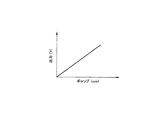
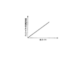
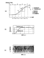
ここで、ギャップセンサ402からの出力は、図11に示すように、回転体401の外周とのギャップに対してほぼ正比例の関係にあり、また、ギャップとカムシャフト134の回転角度とは1対1で対応するため、ギャップセンサ402の出力とカムシャフト134の回転角度とは、図12に示すように、ほぼ正比例の関係となる。従って、ECU114は、ギャップセンサ402からの出力信号に基づいて瞬時に(任意のタイミングで)カムシャフト134の回転角度を検出することができ、この検出した回転角度とクランク角センサ117から出力信号に基づくクランクシャフト120の回転角度とにより、クランクシャフト120に対するカムシャフト134の回転位相を検出できる。
Here, as shown in FIG. 11, the output from the
すなわち、本実施形態におけるECU114は、(1)クランク角センサ117及びカムセンサ132の出力信号に基づいて、吸気側カムシャフト134の回転周期毎に、クランクシャフト120に対する吸気側カムシャフト134の回転位相(吸気バルブ105のバルブタイミング)を検出できる(第1回転位相検出手段)と共に、(2)クランク角センサ117及びギャップセンサ402の出力信号に基づいて、任意のタイミングで連続的に前記回転位相(吸気バルブ105のバルブタイミング)を検出できる(第2回転位相検出手段)。
That is, the
具体的には、第1回転位相検出手段は、基準クランク角信号REFの発生からカム信号CAMの発生までの単位角度信号POSをカウントすることで前記回転位相を検出(算出)し、第2の回転位相検出手段は、ギャップセンサ402の出力信号に基づいて検出した吸気側カムシャフト134の回転角度と、基準クランク角信号REFの発生から吸気側カムシャフト134の回転角度検出までの単位角度信号POSをカウントすることで検出したクランクシャフト120の回転角度とから前記回転位相を検出(算出)する。
Specifically, the first rotational phase detection means detects (calculates) the rotational phase by counting the unit angle signal POS from the generation of the reference crank angle signal REF to the generation of the cam signal CAM, and the second rotational phase detection means The rotation phase detection means detects the rotation angle of the
なお、クランクシャフト120側にも中心からの距離が周方向で徐々に変化する回転体とギャップセンサを設け、該ギャップセンサと上記カムシャフト134側のギャップセンサ402との出力信号に基づいて回転位相を検出するように構成してもよい。
ここで、本実施形態において、ECU114によって実行されるバルブタイミング(回転位相)制御について説明する。なお、以下の説明において第1回転位相検出手段により検出した回転位相を第1回転位相θdet1といい、第2回転位相検出手段により検出した回転位相を第2回転位相θdet2という。
A rotating body and a gap sensor whose distance from the center gradually changes in the circumferential direction are also provided on the
Here, the valve timing (rotation phase) control executed by the
図13は、本実施形態(第1実施形態)に係るバルブタイミング(回転位相)制御のフローチャートであり、キースイッチがONされると開始され、所定時間(例えば、10ms)毎に実行される。
S11では、エンジン回転速度Ne、吸入空気量Qa、冷却水温度Tw等の機関運転状態を読み込む。
FIG. 13 is a flowchart of valve timing (rotation phase) control according to the present embodiment (first embodiment), which starts when the key switch is turned on and is executed every predetermined time (for example, 10 ms).
In S11, the engine operating state such as the engine speed Ne, the intake air amount Qa, the cooling water temperature Tw, etc. is read.
S12では、読み込んだ機関運転状態に基づいて吸気バルブ105の目標バルブタイミング(目標回転位相)θtgを設定する。かかる設定は、例えば、機関負荷及び機関回転速度Neに基づいて、これらに応じてあらかじめ割り付けられた基本目標回転位相マップを参照することにより基本目標回転位相θtg(base)算出し、これを冷却水温度Tw等に応じた補正をすることにより行う。
In S12, the target valve timing (target rotation phase) θtg of the
S13では、吸気バルブ105の実際のバルブタイミング(実回転位相)θdet2を検出する。かかる検出は、クランク角センサ117及びギャップセンサ402の出力信号に基づいて、すなわち、前記第2回転位相検出手段により行う。
S14では、設定した目標回転位相θtgと検出した実際の回転位相θdet2との偏差Erに基づいて、次式のようにしてVTC113(の電磁ブレーキ324)のフィードバック操作量Uを算出する。
In S13, the actual valve timing (actual rotation phase) θdet2 of the
In S14, based on the deviation Er between the set target rotational phase θtg and the detected actual rotational phase θdet2, the feedback operation amount U of the VTC 113 (the electromagnetic brake 324) is calculated as follows.
U=Up+Ui+Ud
Up=Gp*Er
Ui=Gi*Er*Ts+Uiz
Ud=Gd*(Er−Erz)/Ts
ただし、Up:比例操作量(比例項)、Ui:積分操作量(積分項)、Ud:微分操作量(微分項)、Gp:比例ゲイン、Gi:積分ゲイン、Gd:微分ゲイン、Ts:制御周期、Uiz:積分操作量の前回値、Erz:偏差の前回値、である。なお、本実施形態において、前記比例ゲインGpは機関回転速度Neに応じて可変設定されるものであり、その詳細については後述する(図17(c)参照)。
U = Up + Ui + Ud
Up = Gp * Er
Ui = Gi * Er * Ts + Uiz
Ud = Gd * (Er-Erz) / Ts
However, Up: proportional manipulated variable (proportional term), Ui: integral manipulated variable (integral term), Ud: differential manipulated variable (derivative term), Gp: proportional gain, Gi: integral gain, Gd: differential gain, Ts: control Period, Uiz: previous value of integral operation amount, Erz: previous value of deviation. In the present embodiment, the proportional gain Gp is variably set according to the engine rotational speed Ne, and details thereof will be described later (see FIG. 17C).
S15では、算出したフィードバック操作量UをVTC113(の電磁ブレーキ324)に出力して本フローを終了する。
このように、本実施形態では、機関回転の影響を受けずに、任意のタイミングで回転位相を検出できる第2回転位相検出手段によって検出した第2回転位相θdet2(と目標回転位相θtgとの偏差Er)に基づいてバルブタイミング制御を実行する(従って、本実施形態においては、バルブタイミング制御に関して言えば、第1回転位相検出手段を備えなくてもよい)。
In S15, the calculated feedback operation amount U is output to the VTC 113 (the
Thus, in the present embodiment, the deviation between the second rotational phase θdet2 (and the target rotational phase θtg) detected by the second rotational phase detection means that can detect the rotational phase at any timing without being affected by the engine rotation. The valve timing control is executed based on Er) (therefore, in the present embodiment, the first rotational phase detection means may not be provided in terms of the valve timing control).
次に、以上説明した第1実施形態に係るバルブタイミング制御と、従来のバルブタイミング制御、すなわち、第1回転位相検出手段によって検出した第1回転位相θdet1(と目標回転位相θtg)に基づいて行うバルブタイミング制御(従来のバルブタイミング制御という)とを比較する。
図14は、前記第1実施形態に係るバルブタイミング制御結果を示している。
Next, based on the valve timing control according to the first embodiment described above and the conventional valve timing control, that is, based on the first rotation phase θdet1 (and the target rotation phase θtg) detected by the first rotation phase detection means. Compare with valve timing control (referred to as conventional valve timing control).
FIG. 14 shows a valve timing control result according to the first embodiment.
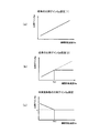
本実施形態では、第2回転位相検出手段により任意のタイミングで前記回転位相を検出することができるので、バルブタイミング制御周期(図中「A」で示す)と回転位相の検出周期(図中「B」で示す)とを合わせることができる(図14(a)参照)。
従って、バルブタイミング制御を行うに際し、実際の回転位相(実回転位相)αと、ECU114が認識する回転位相(すなわち、検出回転位相θdetのことであり、図中βと記す。以下同じ。)とが一致することとなり、そのずれを最小限に抑える(又はなくす)ことができる。この結果、機関回転速度等の影響を受けず、常に、高精度、高応答なバルブタイミング制御を実現でき、また、不要な電力消費も抑制できる(図14(b)、(c)参照)。
In the present embodiment, since the rotational phase can be detected at an arbitrary timing by the second rotational phase detection means, a valve timing control period (indicated by “A” in the figure) and a rotational phase detection period (indicated by “ B ”) (see FIG. 14A).
Therefore, when performing the valve timing control, the actual rotation phase (actual rotation phase) α and the rotation phase recognized by the ECU 114 (that is, the detected rotation phase θdet, denoted as β in the figure, the same applies hereinafter). Are matched, and the deviation can be minimized (or eliminated). As a result, highly accurate and highly responsive valve timing control can always be realized without being affected by the engine rotational speed and the like, and unnecessary power consumption can be suppressed (see FIGS. 14B and 14C).
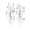
図15は、従来のバルブタイミング制御において、バルブタイミング制御周期Aよりも第1回転位相検出手段による回転位相の検出周期(すなわち、カム信号CAMの出力周期)Bの方が長いときの、言い換えると低回転時におけるバルブタイミング制御結果を示している。
この場合、バルブタイミング制御を行うに際し、実際の回転位相(実回転位相)αと認識回転位相βとに誤差(以下、「認識誤差」ERRという)が発生する(図15(a)参照)。そして、この認識誤差ERRは常に一定とは限らず変動するので、制御系から見ると、応答が遅くなったり、早くなったりすることになる。制御系は、所望の応答になるように操作量を変更するので、認識誤差ERRが変化することによって、操作量の増加・減少が激しくなり応答性が悪化してしまうことになる(図15(b)参照)。また、操作量の振動(増減)により、本実施形態に比べて、消費電力が増大しており、燃費等にも悪影響を与えることになる(図15(c)参照)。
FIG. 15 shows that, in the conventional valve timing control, the rotation phase detection period (that is, the output period of the cam signal CAM) B by the first rotation phase detection means B is longer than the valve timing control period A, in other words. The valve timing control result at the time of low rotation is shown.
In this case, when performing the valve timing control, an error (hereinafter referred to as “recognition error” ERR) occurs between the actual rotational phase (actual rotational phase) α and the recognized rotational phase β (see FIG. 15A). And since this recognition error ERR is not always constant and fluctuates, when viewed from the control system, the response becomes slow or fast. Since the control system changes the manipulated variable so as to obtain a desired response, the increase or decrease of the manipulated variable becomes intense and the responsiveness deteriorates due to the change in the recognition error ERR (FIG. 15 ( b)). Further, the vibration (increase / decrease) in the operation amount increases the power consumption as compared with the present embodiment, and adversely affects the fuel consumption and the like (see FIG. 15C).
図16は、従来のバルブタイミング制御において、バルブタイミング制御周期Aよりも第1回転位相検出手段による回転位相の検出周期(カム信号CAMの出力周期)Bの方が短いとき、言い換えると高回転時におけるバルブタイミング制御結果を示している。
この場合も、図15に示す低回転時と同様に、バルブタイミング制御を行うに際し、実回転位相αと認識回転位相βとに誤差(認識誤差)ERRが発生する(図15(a)参照)。そして、低回転時と同様の理由により、応答性が悪化し、消費電力も増大することになる(図15(b)、(c)参照)。
FIG. 16 shows that in the conventional valve timing control, when the rotation phase detection cycle (the output cycle of the cam signal CAM) B by the first rotation phase detection means is shorter than the valve timing control cycle A, in other words, at the time of high rotation. The valve timing control result in is shown.
Also in this case, an error (recognition error) ERR is generated between the actual rotation phase α and the recognized rotation phase β when performing valve timing control, as in the case of the low rotation shown in FIG. 15 (see FIG. 15A). . And for the same reason as at the time of low rotation, the responsiveness deteriorates and the power consumption increases (see FIGS. 15B and 15C).
以上の結果からも明らかなように、本実施形態によれば、前記第2回転位相検出手段によって、カムシャフト134の回転周期とは無関係に、任意のタイミングでクランクシャフト120に対するカムシャフト134の回転位相を検出できるので、その検出周期をバルブタイミング制御周期に合わせることができ、実回転位相と制御に用いる回転位相(認識回転位相)との誤差(認識誤差)がほとんど発生しない。従って、従来のものに比べて、バルブタイミング制御の制御性を向上できると共に燃費についても有利である。
As is apparent from the above results, according to the present embodiment, the second rotation phase detection unit rotates the
ところで、従来のものでは、低回転時においてバルブタイミング制御周期Aより回転位相検出周期Bが長くなることから、回転位相が更新される間は、実際とは異なる同一の回転位相を用いて繰り返しフィードバック制御が行われることとなり、オーバーシュートが発生するおそれがあるために、例えば、図17(a)、(b)に示すように、機関回転速度が低いときにはフィードバック制御ゲイン(比例ゲインGp)を小さく設定して対応するようにしていた。 By the way, in the conventional system, since the rotational phase detection period B is longer than the valve timing control period A at the time of low revolution, while the rotational phase is updated, feedback is repeatedly performed using the same rotational phase that is different from the actual one. For example, as shown in FIGS. 17 (a) and 17 (b), when the engine speed is low, the feedback control gain (proportional gain Gp) is decreased. It was set and supported.
一般に、低回転時は、VTC113における(回転)摺動抵抗が大きくなって高回転時に比べて応答性が低くなってしまうところ、さらに、上記のようにフィードバック制御ゲインを小さく設定せざるを得ないことから、制御応答性という面ではかなり不利な状態となっていた。
これに対し、本実施形態ではバルブタイミング制御周期Aと回転位相の検出周期Bとを合わせて実回転位相と認識回転位相とを一致させることができるので(図14参照)、低回転時であっても上記したようなオーバーシュートが発生するおそれがない。
In general, at low rotation, the (rotational) sliding resistance in the
On the other hand, in the present embodiment, the valve timing control cycle A and the rotation phase detection cycle B can be combined to match the actual rotation phase and the recognized rotation phase (see FIG. 14). However, there is no risk of overshooting as described above.
そこで、本実施形態においては、低回転時においては、機関回転速度が低いほどフィードバック制御ゲイン(比例ゲインGp)を大きく設定するようにしている。
具体的には、図17(c)に示すように、応答性という観点から、VTC113における摺動抵抗の影響をほとんど受けなくなる機関回転速度をあらかじめ求めて、これを所定回転速度Ns1として設定しておき、機関回転速度Ne≧所定回転速度Ns1であれば比例ゲインGp=k(一定値)とする一方、Ne<Ns1であればNeが小さいほど大きな比例ゲインGpを設定する。
Therefore, in this embodiment, at the time of low rotation, the feedback control gain (proportional gain Gp) is set to be larger as the engine rotational speed is lower.
Specifically, as shown in FIG. 17C, from the viewpoint of responsiveness, an engine rotational speed that is hardly affected by the sliding resistance in the
このように、低回転時においては機関回転速度Neが低いほどフィードバックゲイン(比例ゲインGp)を大きく設定することにより、VTC113における摺動抵抗の増加に伴う応答性の低下分を補うようにフィードバック制御ゲインが設定されることとなり、低回転時における制御性(応答性)を更に向上できることになる。
ここで、上記図15、図16に示すように、前記認識誤差ERRは、高回転時に比べて低回転時が大きくなることから、低回転時にのみ前記第2回転位相検出手段によって回転位相を検出するようにし、中・高回転時は、従来のように、前記第1回転位相検出手段によって回転位相を検出するようにしてもよい。このように、機関回転速度に応じて回転位相の検出、ひいては、バルブタイミング制御を切り換えるようにしたものが、以下に説明する第2実施形態に係るバルブタイミング制御である。
As described above, at the time of low rotation, the feedback gain (proportional gain Gp) is set to be larger as the engine rotational speed Ne is lower, so that the feedback control is compensated to compensate for the decrease in responsiveness accompanying the increase in sliding resistance in the
Here, as shown in FIG. 15 and FIG. 16, the recognition error ERR is larger at low rotation than at high rotation. Therefore, the rotation phase is detected by the second rotation phase detection means only at low rotation. In the middle / high rotation, the rotation phase may be detected by the first rotation phase detection means as in the prior art. The valve timing control according to the second embodiment described below is such that the detection of the rotation phase and, consequently, the valve timing control is switched in accordance with the engine rotation speed.
この実施形態では、第1回転位相検出手段による回転位相の検出周期がバルブタイミング制御周期よりも長くなる低回転時には、第2回転位相検出手段により検出した回転位相に基づいてバルブタイミング制御を行い、上記のような不都合が少ない中・高回転時には、第1回転位相検出手段により検出した回転位相に基づいてバルブタイミング制御を行うようにしている。 In this embodiment, at the time of low rotation when the rotation phase detection period by the first rotation phase detection means is longer than the valve timing control period, valve timing control is performed based on the rotation phase detected by the second rotation phase detection means, At the time of middle / high rotation with few inconveniences as described above, valve timing control is performed based on the rotation phase detected by the first rotation phase detection means.
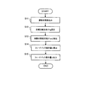
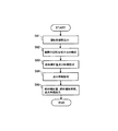
図18は、第2実施形態に係るバルブタイミング(回転位相)制御を示すフローチャートであり、前記第1実施形態と同様、キースイッチがONされると開始され、所定時間(例えば、10ms)毎に実行される。
S21では、機関回転速度Ne、吸入空気量Qa、冷却水温度Tw等の機関運転状態を読み込む。
FIG. 18 is a flowchart showing valve timing (rotation phase) control according to the second embodiment. As in the first embodiment, the control is started when the key switch is turned on, and every predetermined time (for example, 10 ms). Executed.
In S21, the engine operating state such as the engine speed Ne, the intake air amount Qa, the cooling water temperature Tw, etc. is read.
S22では、読み込んだ機関運転状態に基づいて目標回転位相(目標バルブタイミング)θtgを設定する。
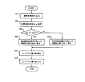
S23では、機関回転速度Neが予め設定した所定回転速度Ns2以下であるか否かを判定する。Ne≦Ns2であればS24に進み、Ne>Ns2であればS25に進む。なお、所定回転速度Ns2は、前記第1回転位相検出手段による回転位相の検出周期(すなわち、カムシャフト134の回転周期)がバルブタイミング制御周期よりも長くなる機関回転速度の値(若しくはその近傍の値)を設定する。
In S22, a target rotation phase (target valve timing) θtg is set based on the read engine operating state.
In S23, it is determined whether or not the engine rotational speed Ne is equal to or lower than a predetermined rotational speed Ns2. If Ne ≦ Ns2, the process proceeds to S24, and if Ne> Ns2, the process proceeds to S25. The predetermined rotational speed Ns2 is an engine rotational speed value at which the rotational phase detection period (that is, the rotational period of the camshaft 134) by the first rotational phase detection means is longer than the valve timing control period (or a value in the vicinity thereof). Value).
S24では、クランク角センサ117及びギャップセンサ402の出力信号に基づいて、すなわち、前記第2回転位相検出手段により第2回転位相θdet2を検出する。
S25では、前記第1回転位相検出手段により検出した第1回転位相θdet1を読み込む(図19〜21参照)。
S26では、目標回転位相θtgと、第1回転位相θdet1又は第2回転位相θdet2との偏差Eに基づいて、VTC113(電磁ブレーキ324)のフィードバック操作量Uを算出する。なお、算出方法は、図13におけるS14と同様である。
In S24, based on the output signals of the crank angle sensor 117 and the
In S25, the first rotation phase θdet1 detected by the first rotation phase detection means is read (see FIGS. 19 to 21).
In S26, the feedback operation amount U of the VTC 113 (electromagnetic brake 324) is calculated based on the deviation E between the target rotation phase θtg and the first rotation phase θdet1 or the second rotation phase θdet2. The calculation method is the same as S14 in FIG.
S27では、算出したフィードバック操作量UをVTC113に出力して本フローを終了する。
図19〜21は、クランク角センサ及びカムセンサの出力信号に基づいて、すなわち、第1回転位相検出手段により回転位相θdet1を検出するフローチャートである。
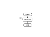
図19は、単位角度信号POSのカウント値CPOSのリセット処理を行うフローチャートであり、クランク角センサ117から基準クランク信号REFが出力されると実行される。S31では、クランク角センサ117からの単位角度信号POSのカウント値CPOSを0とする。
In S27, the calculated feedback manipulated variable U is output to the
19 to 21 are flowcharts for detecting the rotational phase θdet1 based on the output signals of the crank angle sensor and the cam sensor, that is, by the first rotational phase detection means.
FIG. 19 is a flowchart for resetting the count value CPOS of the unit angle signal POS, which is executed when the reference crank signal REF is output from the crank angle sensor 117. In S31, the count value CPOS of the unit angle signal POS from the crank angle sensor 117 is set to zero.
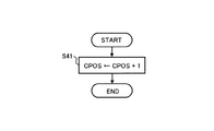
図20は、単位角度信号POSのカウント値CPOSのカウントアップ処理を行うフローチャートであり、クランク角センサ117から単位角度信号POSが出力されると実行される。S41では、カウント値CPOSを1アップする。
以上の図19、20のフローにより、前記カウント値CPOSは基準クランク角信号REFの発生時に0にリセットされ、その後の単位角度信号POSの発生数を計数した値となる。
FIG. 20 is a flowchart for counting up the count value CPOS of the unit angle signal POS, which is executed when the unit angle signal POS is output from the crank angle sensor 117. In S41, the count value CPOS is incremented by one.
19 and 20, the count value CPOS is reset to 0 when the reference crank angle signal REF is generated, and becomes a value obtained by counting the number of subsequent unit angle signals POS generated.
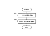
図21は、第1回転位相θdet1を検出するフローチャートであり、カムセンサ132からカム信号CAMが出力されると実行される。
S51では、基準クランク角信号REFの発生からカム信号CAMの発生までの前記カウント値CPOSを読み込む。
S52では、読み込んだカウント値CPOSに基づいて第1回転位相θdet1を検出する。つまり、第1回転位相検出手段では、カム信号CAMが出力される毎(クランク角180°毎)に、クランクシャフト120に対するカムシャフト134の回転位相(第1回転位相)が検出されることになる。
FIG. 21 is a flowchart for detecting the first rotational phase θdet1 and is executed when the cam signal CAM is output from the
In S51, the count value CPOS from the generation of the reference crank angle signal REF to the generation of the cam signal CAM is read.
In S52, the first rotation phase θdet1 is detected based on the read count value CPOS. In other words, the first rotation phase detection means detects the rotation phase (first rotation phase) of the
このように、第1回転位相検出手段による回転位相の検出周期がバルブタイミング制御周期よりも長くなる低回転時には、第2回転位相検出手段によって検出した第2回転位相θdet2に基づいてバルブタイミング制御を行うことにより、バルブタイミング制御周期に対して回転位相の検出周期が長くなる不都合(すなわち、認識誤差ERRによる制御性の悪化)を回避して高応答・高精度なバルブタイミング制御が実現できる一方、上記のような不都合がない中・高回転時には、第1回転位相検出手段により検出した第1回転位相θdet1に基づいてバルブタイミング制御を行うことにより、安定したバルブタイミング制御を実現できる。 In this way, at the time of low rotation in which the rotation phase detection period by the first rotation phase detection means is longer than the valve timing control period, the valve timing control is performed based on the second rotation phase θdet2 detected by the second rotation phase detection means. By doing so, it is possible to avoid the inconvenience that the rotation phase detection cycle becomes longer than the valve timing control cycle (that is, the deterioration of controllability due to the recognition error ERR), and realize a highly responsive and highly accurate valve timing control, At the time of middle / high rotation without such inconvenience, stable valve timing control can be realized by performing valve timing control based on the first rotation phase θdet1 detected by the first rotation phase detection means.
なお、以上の説明では、機関回転速度Neと所定回転速度Ns2とを比較することによって低回転時を判定してバルブタイミング制御を切り換えるようにしているが(S23)、第1回転位相検出手段による回転位相の検出周期がバルブタイミング制御周期よりも長い状態であって認識誤差ERRが大きい状態を判定できれば他の方法により判定するようにしてもよい。 In the above description, the engine rotation speed Ne is compared with the predetermined rotation speed Ns2 to determine the low rotation time and the valve timing control is switched (S23). If the rotation phase detection cycle is longer than the valve timing control cycle and the recognition error ERR is large, it may be determined by another method.
例えば、(a)第1回転位相検出手段による回転位相θdet1の検出(すなわち、カム信号CAMの出力)からの経過時間を計測し、所定時間T1経過するまでにバルブタイミング制御が実行されない場合を低回転時と判定するようにしたり、(b)機関始動から所定時間T2経過するまでを低回転時と判定するようにしたり、(c)機関始動からの機関回転速度をモニタし、アイドル回転が安定するまで(例えば、前回値との差ΔNeが所定量以下となるまで)を低回転時(この場合は始動時)と判定するようにしてもよい。 For example, (a) the time elapsed from the detection of the rotational phase θdet1 by the first rotational phase detection means (that is, the output of the cam signal CAM) is measured, and the valve timing control is not performed until the predetermined time T1 has elapsed. It is determined that the engine is rotating, (b) it is determined that the engine is at a low engine speed until a predetermined time T2 has elapsed since the engine is started, and (c) the engine speed after the engine is started is monitored to stabilize the idle rotation. Until the difference (for example, until the difference ΔNe from the previous value becomes equal to or less than a predetermined amount) may be determined as the time of low rotation (in this case, at the start).
また、吸気バルブ105にVTC113を備えたものについて説明しているが、排気バルブ107側にVTC113を備えた場合であっても同様である。
ところで、上記実施形態では、吸気バルブ105の実際のバルブタイミング(実回転位相)θdetを任意のタイミングで連続的に検出する第2回転位相検出手段として、クランク角センサ117及びギャップセンサ402を用いているが、これに限られるものではない。例えば、上記VTC(以下、「第1VTC」という)113に対して以下のように構成したVTC(以下、「第2VTC」という)213を用いることで、吸気バルブ105の実際のバルブタイミング(実回転位相)θdetを任意のタイミングで連続的に検出するようにしてもよい。
In addition, although the
By the way, in the above embodiment, the crank angle sensor 117 and the
以下、第2VTC213の構成を、図22〜図29を参照して説明する。
なお、この第2VTC213も、ゼンマイばねの力とヒステリシスブレーキの制動力とによって位相を変更・保持するものであり、上述した第1VTC113と同一又は類似する構成要素を有しているが、便宜上、全構成について説明する。なお、第1VTC113では各構成要素の符号として300番台を用いるのに対して、第2VTC213では500番台を用いる。
Hereinafter, the configuration of the
The
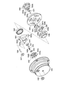
第2VTC213は、図22に示すように、カムシャフト134の前端部に相対回動できるように組み付けられ、タイミングチェーン(図示せず)を介してクランクシャフト120に連係されるタイミングスプロケット502と、このタイミングスプロケット502の内周側に配置されて、タイミングスプロケット502とカムシャフト134との組付角を操作する組付角操作機構504と、この組付角操作機構504よりもカムシャフト134よりの後方側に配置されて、該組付角操作機構504を駆動する操作力付与手段505と、前記タイミングスプロケット502に対するカムシャフト13の相対回転変位角(回転位相)を検出する相対変位検出手段506と、シリンダヘッドのヘッドカバーに取り付けられて、前記組付角操作機構504及び相対変位検出手段506の前面を覆うVTCカバー532とを備えている。
As shown in FIG. 22, the
ここで、図2と図22とを比較すれば明らかなように、第1VTC113と第2VTC213とは、概して次の点において相違している。
まず、第2VTC213では、操作力付与手段505が組付角操作機構504のカムシャフト134側に配置されていることである。従って、第2VTC213の組付角操作機構504及び操作力付与手段505の構成要素の配置は、VTC113の組付角操作機構304及び操作力付与手段305の構成要素の配置と、図で見て左右逆転している(もちろん、この相違に伴う変更等もある)。
Here, as apparent from a comparison between FIG. 2 and FIG. 22, the
First, in the
次に、タイミングスプロケット502に対するカムシャフト134の相対変位角を検出する相対変位角検出手段506が設けられていることである。この相対変位角検出手段506が前記第2回転位相検出手段に相当し、吸気バルブ105の実際のバルブタイミング(実回転位相)θdetを任意のタイミングで連続的に検出する。従って、第2VTC213においては、第1VTC113における回転体401及びギャップセンサ402は不要となる。
Next, relative displacement angle detection means 506 for detecting the relative displacement angle of the
第2VTC213において、前記カムシャフト134の端部には、従動軸部材507がカムボルト510によって固定されている。
前記従動軸部材507には、フランジ507aが一体に設けられている。
前記タイミングスプロケット502は、前記タイミングチェーンが噛み合う歯車部503が形成された大径の円筒部502aと、小径の円筒部502bと、前記円筒部502aと円筒部502bとの間を連結する円板部502cとから構成される。
In the
The driven
The
前記円筒部502bは、前記従動軸部材507のフランジ507aに対してボールベアリング530によって回転可能に組み付けられている。
前記円板部502cの円筒部502b側の面には、図23〜図25(図22のA−A断面に相当する)に示すように、三つ溝508がタイミングスプロケット502の半径方向に沿って放射状に形成されている。
The cylindrical portion 502b is assembled to the
As shown in FIGS. 23 to 25 (corresponding to the AA cross section in FIG. 22), three
また、前記従動軸部材507のフランジ部507aのカムシャフト134側端面には、径方向に放射状に突出する3つの突起部509が一体に形成されている
各突起部509には、3つのリンク511の基端がそれぞれピン512によって回転可能に連結される。
前記各リンク511の先端には、前記各溝508に摺動自在に係合する円柱状の突出部513が一体に形成されている。
Further, on the end surface of the
A
前記各リンク511は、各突出部513が対応する溝508に係合した状態において、ピン512を介して前記従動軸部材507に連結されているため、リンク511の先端側が外力を受けて溝508に沿って変位すると、タイミングスプロケット502と従動軸部材507とは、各リンク511の作用によって相対的に回動する。
また、前記各リンク511の突出部513には、カムシャフト134側に向けて開口する収容穴514が形成される。
Since each link 511 is connected to the driven
In addition, a
前記収容穴514には、後述する渦巻き溝515に係合する係合ピン516と、この係合ピン516を前記渦巻き溝515側に向けて付勢するコイルばね517とが収容されている。
一方、前記突起部509よりもカムシャフト134側の従動軸部材507には、円板状の中間回転体518が軸受529を介して回転自在に支持されている。
The
On the other hand, a disk-shaped intermediate
この中間回転体518の端面(突起部509側)には、渦巻き溝515が形成され、この渦巻き溝515に、前記各リンク511の先端の係合ピン516が係合される。
前記渦巻き溝515は、タイミングスプロケット502の回転方向に沿って次第に縮径するように形成されている。
従って、各係合ピン516が渦巻き溝515に係合した状態において、中間回転体518がタイミングスプロケット502に対して遅れ方向に相対変位すると、各リンク511の先端部は、溝508に案内されつつ渦巻き溝515に誘導されて半径方向内側に向けて移動する。
A
The
Therefore, when the intermediate
逆に、中間回転体518がタイミングスプロケット502に対して進み方向に相対変位すると、各リンク511の先端部は半径方向外側に向けて移動する。
前記組付角操作手段504は、前記タイミングスプロケット502の溝508、リンク511、突出部513、係合ピン516、中間回転体518、渦巻き溝515等によって構成されている。
On the contrary, when the intermediate
The assembly angle operating means 504 includes a
前記操作力付与手段505から中間回転体518に対して回動操作力が入力されると、リンク511の先端が径方向に変位し、該変位がリンク511を介してタイミングスプロケット502と従動軸部材507との相対変位角を変化させる回動力として伝達される。
前記操作力付与手段505は、中間回転体518をタイミングスプロケット502の回転方向に付勢するゼンマイばね519と、中間回転体518をタイミングスプロケット502の回転方向とは逆方向に回動させる制動力を発生するヒステリシスブレーキ520とを備える。
When a turning operation force is input from the operation force applying means 505 to the intermediate
The operating force applying means 505 includes a
ここで、前記ECU114が、内燃機関101の運転状態に応じてヒステリシスブレーキ520の制動力を制御することにより、ゼンマイばね519の付勢力と前記ヒステリシスブレーキ520の制動力とがバランスする位置にまで、中間回転体518をタイミングスプロケット502に対して相対回転させることができるようになっている。
前記ゼンマイばね519は、図26に示すように、前記タイミングスプロケット502の円筒部502a内に配置され、その外周端部519aが円筒部502aの内周に係合され、内周端部519bが中間回転体518の基部518aの係合溝518bに係合されている。
Here, the
As shown in FIG. 26, the
前記ヒステリシスブレーキ520は、ヒステリシスリング523と、磁界制御手段としての電磁コイル524と、該電磁コイル524の磁気を誘導するコイルヨーク525とを備える。
前記ヒステリシスリング523は、前記中間回転体518の後端部に対して、リテーナプレート522、及び、該リテーナプレート522の後端面に一体に設けられた突起522aを介して取り付けられる。
The
The
前記電磁コイル524への通電(励磁電流)は、機関の運転状態に応じてECU114が制御する。
前記ヒステリシスリング523は、円筒部523aと、この円筒部523aがビス523cによって結合される円板状の基部523bとから構成される。
前記基部523aは、円周方向の等間隔位置に設けられたブッシュ521内に前記各突起522aが圧入されることによって、リテーナプレート522に対して結合されるようになっている。
The energization (excitation current) to the
The
The
また、前記ヒステリシスリング523は、外部の磁界変化に対して位相遅れをもって磁束が変化する特性をもつ材料によって形成され(第1VTCと同様であり、図6参照)、前記円筒部523aが前記コイルヨーク525によって制動作用を受けるようになっている。
前記コイルヨーク525は、電磁コイル524を取り囲むように形成され、外周面が図外のシリンダヘッドに固定されている。
The
The
また、前記コイルヨーク525の内周側は、ニードル軸受528を介してカムシャフト134を回転自在に支持していると共に、ボールベアリング531によって前記ヒステリシスリング523の基部523a側を回転自在に支持している。
そして、前記コイルヨーク525の中間回転体518側には、環状の隙間を介して向かい合う一対の対向面526、527が形成されている。
In addition, the inner peripheral side of the
A pair of
前記対向面526、527には、磁界発生部を構成する複数の凸部526a、527aが周方向に沿って等間隔に形成されている(第1VTCと同様であり、図4参照)。
そして、一方の対向面526の凸部526aと他方の対向面527の凸部527aとは円周方向に交互に配置され、対向面526、527相互の近接する凸部526a、527aがすべて円周方向にずれている。
On the opposing
And the
従って、両対向面526、527の近接する凸部526a、527a間には、電磁コイル524の励磁によって円周方向に傾きをもった向きの磁界が発生する(第1VTCと同様であり、図7、図8参照)。
そして、両対向面526、527間の隙間には、前記ヒステリシスリング523の円筒部523aが非接触状態で介装されている。
Therefore, a magnetic field having a direction inclined in the circumferential direction is generated by the excitation of the
A
前記ヒステリシスリング523が対向面526、527間の磁界内を変位するときに、ヒステリシスリング523内部の磁束の向きと磁界の向きのずれによって制動力が発生する。前記制動力は、対向面526、527とヒステリシスリング523との相対速度に関係なく、磁界の強さ、即ち、電磁コイル524の励磁電流の大きさに略比例した値となる(第1VTC113と同様であり、図9参照)。
When the
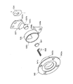
前記相対変位検出手段506は、図22、27、28に示すように、前記従動軸部材507側に設けられた磁界発生機構と、固定部側であるVTCカバー532側に設けられて、前記磁界発生機構からの磁界の変化を検出するセンサ機構とから構成されている。
前記磁界発生機構は、前記従動軸部材507のフランジ507aの前端側に固定された非磁性材からなるマグネットベース533と、該マグネットベース533の先端部に形成された溝533a内に収容され、ピン533cによって固定される永久磁石534と、前記タイミングスプロケット502の円筒部502bの先端縁に固定されたセンサベース535と、該センサベース535の前端面に円筒状のヨークホルダー536を介して固定された第1、2ヨーク部材537、538とを備えている。なお、前記マグネットベース533の外周面と前記センサベース535の内周面との間には、センサ機構へのゴミなどの侵入を防止するシール部材551が介装されている。
22, 27, and 28, the relative displacement detection means 506 is provided on the driven
The magnetic field generating mechanism is housed in a
前記マグネットベース533は、図27に示すように、図で見て上下が開放される溝533aを形成する一対の突起壁533b、533bを有し、この両突起壁533b、533bの間に前記永久磁石534が収容される。
前記永久磁石534は、溝533aの形状に対応するよう小判型に形成されており、その上端部中央と下端部中央とが、それぞれN極とS極の中心に設定されている。
As shown in FIG. 27, the
The
前記第1ヨーク部材537は、図27及び図28に示すように、前記センサベース535に固定されるプレート状の基部537aと、該基部537aの内周縁に一体に設けられる扇状ヨーク部537bと、該扇状ヨーク部537bの要の部分に一体に設けられた円柱状の中央ヨーク部537cとから構成されている。なお、前記中央ヨーク部537cは、その後端面が前記永久磁石534の前面に配置されている。
As shown in FIGS. 27 and 28, the
前記第2ヨーク部材538は、センサベース535に固定されるプレート状の基部538aと、該基部538aの上端縁に一体に設けられたプレート状の円弧ヨーク部538bと、該円弧ヨーク部538bの後端部に同じ曲率で一体に設けられた円環ヨーク部538cとから構成されている。なお、前記円環ヨーク部538cは、後述する第4ヨーク部材542の外周側を囲むように配置されている。
The
前記センサ機構は、円環状の素子ホルダー540と、整流ヨークである第3ヨーク部材541と、整流ヨークである有底円筒状の第4ヨーク部材542と、合成樹脂製の保護キャップ543と、保護部材544と、ホール素子545とを備えている。
前記素子ホルダー540は、前記VTCカバー532の内側に配置され、圧入等により固定されるボールベアリング539を介して前記ヨークホルダー536の前端部を回転自在に支持する。また、図27に示すように、円周方向等間隔に3つの突起部540aが一体に設けられていると共に、該各突起部540aに穿設された固定用孔にピン546の一端がそれぞれ圧入固定されている。
The sensor mechanism includes an
The
また、VTCカバー532の内面と第4ヨーク部材542との間に介装されたコイルスプリング549のばね力によって、前記ボールベアリング539の外輪をカムシャフト134方向に付勢して軸方向の位置決めとガタの発生を防止している。
VTCカバー532の内部側には、円周方向に等間隔で三つの孔532aが形成されており、各孔532aの内部にゴムブッシュ547がそれぞれ固定される。各ゴムブッシュ547の中央に穿設された孔には、前記ピン546の他端部が挿通され、これにより、素子ホルダー540を前記VTCカバー532に支持する。なお、VTCカバー532には、前記各保持孔506aの外側開口を閉塞する栓体548が螺着されている。
Further, the outer ring of the
Three
前記第3ヨーク部材541は、ほぼ円形状に形成されており、前記第1ヨーク部材537の中央ヨーク部537cに対して所定量(例えば、約1mm)のエアギャップGを介して対向配置される。なお、第2ヨーク部材538の円環ヨーク部538cの内周面と第4ヨーク部材542の円筒部542bの外周面との間にも、エアギャップG1が形成されている。
The
前記第4ヨーク部材542は、前記素子ホルダー540の内周にボルト等により固定されており、素子ホルダー540に固定される円板状基部542aと、該基部542aのホール素子545側端面に一体に設けられる小径の円筒部542bと、該円筒部542bで囲まれる底壁に設けられる円柱状の突起542cを備える。前記突起542cは、前記永久磁石534、第1ヨーク部材537の中央ヨーク部537c、第3ヨーク部材541と同軸に配置される。
The
前記保護キャップ543は、前記第4ヨーク部材542の円筒部542bの内周面に固定されて、前記第3ヨーク部材541を保持する。
前記保護部材544は、前記第4ヨーク部材542の円柱状突起542cの外周に嵌着される。
前記ホール素子545は、前記第3ヨーク541と第4ヨーク542の突起542cとの間に保持され、そのリード線545aは、前記ECU114に接続されている。
The
The
The
以上のような構成の第2VTC213においても、機関回転中(例えば、停止前のアイドル運転中)にヒステリシスブレーキ520の電磁コイル524の励磁がオフされると、ゼンマイばね519の力によって中間回転体318がタイミングスプロケット302に対して機関回転方向に最大に回転される(図23参照)。これにより、クランクシャフト120に対するカムシャフト134の回転位相は、吸気バルブ105のバルブタイミングが最も遅れる最遅角側(最遅角タイミング)に維持される。
Also in the
この状態から前記回転位相を最進角側に変更すべき指令が前記ECU114から発されると、ヒステリシスブレーキ520の電磁コイル524の励磁がオンされ、ゼンマイばね519の力に抗する制動力が中間回転体518に付与される。これにより、中間回転体518がタイミングスプロケット502に対して回転移動し、リンク511の先端の係合ピン516が渦巻き溝515に誘導されてリンク511の先端部が径方向溝508に沿って変位し、タイミングスプロケット502と従動軸部材507の組付角が最進角側に変更される(図24参照)。この結果、前記回転位相は、吸気バルブ105のバルブタイミングが最も進む最進角側(最進角タイミング)となる。
When a command to change the rotational phase from the state to the most advanced angle is issued from the
さらに、この状態(最進角側)から前記回転位相を最遅角側に変更すべき指令が前記ECU114から発されると、ヒステリシスブレーキ520の電磁コイル524の励磁がオフにされ、再度ゼンマイばね519の力によって中間回転体518が戻す方向に回転移動する。すると、渦巻き溝515による係合ピン516の誘導によってリンク511が上記と逆方向に揺動し、図24に示すように、タイミングスプロケット502と従動軸部材507の組付角が再度最遅角側に変更される。
Further, when a command to change the rotational phase from the state (the most advanced angle side) to the most retarded angle side is issued from the
なお、この第2VTC213も、第1VTC113と同様に、例えば図2に示す中間的な進角状態のように、ヒステリシスブレーキ520の制動力の制御によって任意の位相に変更することができ、ゼンマイばね519の力とヒステリシスブレーキ520の制動力のバランスによってその位相を保持することもできる。
また、機関停止中は電磁コイル524の励磁がオフされることになるが、機関停止中はフリクションが大きく前記中間回転体518を回転させるには、より大きな力が必要となるため、機関回転中のように前記ゼンマイばね519の力のみで前記中間回転体518を遅角側(戻す方向)へと回転させることはできない。このため、機関停止中は、停止直前に制御されたバルブタイミングがほとんどそのまま維持されることになる。
Similarly to the
Further, while the engine is stopped, the excitation of the
ここで、前記相対変位検出手段506による相対変位角度(回転位相)の検出について説明する。相対変位角度の検出は以下のようにして行われる。なお、図29は、相対変位検出手段506を模式的に示したものである。
図29に示すように、前記カムシャフト134とタイミングスプロケット502との相対回転位相が変化して、前記永久磁石534が、例えば角度θだけ回転すると、N極の中心Pから出力された磁界Zは、第1ヨーク部材537の扇状ヨーク部537bに伝達され、中央ヨーク部537cに伝達され、更に、エアギャップGを介して第3ヨーク部材541を経てホール素子545に伝達される。
Here, detection of the relative displacement angle (rotation phase) by the relative displacement detection means 506 will be described. The relative displacement angle is detected as follows. FIG. 29 schematically shows the relative displacement detection means 506.
As shown in FIG. 29, when the relative rotational phase of the
前記ホール素子545に伝達された磁界Zは、ホール素子545から第4ヨーク部材542の突起542cを介して第4ヨーク部材542の円筒部542bに伝達され、さらにここからエアギャップG1を介して第2ヨーク部材538の円環ヨーク部538cに伝達され、円弧ヨーク部538bを介して永久磁石534のS極に戻るようになっている。
前記永久磁石534の回転角度θの連続的な変化によって前記磁界Zの磁束密度が連続的に変化することから、この磁束密度の連続的な変化を前記ホール素子545が検出してその電圧変化を前記ECU114に出力する。
The magnetic field Z transmitted to the
Since the magnetic flux density of the magnetic field Z changes continuously due to the continuous change of the rotation angle θ of the
ECU114は、ホール素子545からリード線545aを介して出力された連続的な検出信号(電圧変化)に基づいてクランクシャフト120に対するカムシャフト13の相対回転変位角(回転位相の進角値)を演算によって求める。
このように、第2VTC213では、永久磁石534の回転角度の変化による磁束密度の変化を検出するホール素子545が前記第2回転位相検出手段に相当することになる。
The
Thus, in the
従って、第1VTC113に代えて第2VTC213を用いた場合においても、バルブタイミング制御周期に合わせて回転位相を検出することができるので、実回転位相と制御に用いる回転位相(認識回転位相)との誤差(認識誤差)がほとんど発生しない。このため、従来に比べて、バルブタイミング制御の制御性を向上できると共に燃費についても有利である。
Therefore, even when the
ここで、前記第1VTC113においては、クランクシャフトの回転位置(角度)とカムシャフトの回転位置(角度)とをそれぞれ検出し、検出したクランクシャフトの回転位置(角度)及びカムシャフトの回転位置(角度)から前記回転位相を検出(算出)するのに対して、第2VTC213においては、クランクシャフト及びカムシャフトの回転位置(角度)を検出することなく、ホール素子545の検出信号(ホール素子545からの出力信号)から前記回転位相を「直接(直ちに)」検出することができる。
Here, in the
なお、以上説明した実施形態では、吸気バルブ105にVTC113、213を備えたものについて説明しているが、排気バルブ107側に備えた場合であっても同様である。
また、第2回転位相検出手段は、クランクシャフト120に対する吸気側カムシャフト134の回転位相を任意のタイミングで検出できれば上述したものに限るものではなく、また、少なくとも吸気側カムシャフト134の回転周期よりも短い周期で回転位相を検出できるものであれば、第2回転位相検出手段として用いることができる。
In the embodiment described above, the
The second rotational phase detection means is not limited to that described above as long as the rotational phase of the
また、以上では電磁式のVTCについて説明したが、油圧式のVTC(例えば、機関始動時に油圧を上昇させる手段を備えたもの)に対して適用してもよい。
さらに、バルブタイミング制御のみならず、任意のタイミングで検出できる前記第2回転位相θdet2を用いて燃料噴射制御や点火時期制御を実行するようにしてもよい。
図30は、かかる燃料噴射制御、点火時期制御を示すフローチャートであり、例えば、機関始動直後等の低回転時に実行される。
Further, the electromagnetic VTC has been described above. However, the present invention may be applied to a hydraulic VTC (for example, one having a means for increasing the hydraulic pressure when the engine is started).
Furthermore, not only valve timing control but also fuel injection control and ignition timing control may be executed using the second rotational phase θdet2 that can be detected at an arbitrary timing.
FIG. 30 is a flowchart showing such fuel injection control and ignition timing control, and is executed, for example, at a low speed immediately after the engine is started.
S61では、機関回転速度Ne、吸入空気量Qa、冷却水温度Tw等の機関運転状態を読み込む。
S62では、第2回転位相検出手段により実際の回転位相(実バルブタイミング)θdet2を検出する。
S63では、読み込んだ機関運転状態と検出した実際の回転位相θdet2とに基づいて、燃料噴射量及び時期を設定する。かかる設定は、例えば、機関運転状態に応じて割り付けられた基本燃料噴射量マップ、基本燃料噴射時期マップを参照して、基本燃料噴射量及び時期を算出し、これを実際の回転位相θdet2に応じて補正することにより行う。
In S61, the engine operating state such as the engine speed Ne, the intake air amount Qa, the cooling water temperature Tw, etc. is read.
In S62, the actual rotational phase (actual valve timing) θdet2 is detected by the second rotational phase detection means.
In S63, the fuel injection amount and timing are set based on the read engine operating state and the detected actual rotational phase θdet2. For this setting, for example, the basic fuel injection amount and the timing are calculated with reference to the basic fuel injection amount map and the basic fuel injection timing map assigned according to the engine operating state, and this is calculated according to the actual rotational phase θdet2. This is done by correcting.
S64では、読み込んだ機関運転状態と検出した実際の回転位相θdet2とに基づいて、点火時期を設定する。かかる設定は、例えば、機関運転状態に応じて割り付けられた基本点火時期マップを参照して基本点火時期算出し、これを実際の回転位相θdet2に応じて補正することにより行う。
S65では、算出した燃料噴射量及び燃料噴射時期に応じた駆動パルス信号を燃料噴射弁131に出力し、算出した点火時期の応じた駆動信号を点火プラグ133に出力する。
In S64, the ignition timing is set based on the read engine operating state and the detected actual rotational phase θdet2. Such a setting is performed, for example, by calculating a basic ignition timing with reference to a basic ignition timing map assigned according to the engine operating state, and correcting this based on the actual rotational phase θdet2.
In S65, a drive pulse signal corresponding to the calculated fuel injection amount and fuel injection timing is output to the
このように、本実施形態では、第2回転位相検出手段により、カムシャフト134の回転周期とは無関係に、任意のタイミングでクランクシャフト120に対するカムシャフト134の回転位相を検出できるので、燃料噴射及び点火タイミングの設定時点における実際の回転位相を検出し、この検出結果に応じて燃料噴射量、燃料噴射時期、点火時期を設定(補正)することができ、最適な燃料噴射制御及び点火時期制御を実現できる。これにより、特に始動直後の低回転時において、エミッションの悪化や燃焼不安定な状態を回避することができる。
As described above, in the present embodiment, the second rotation phase detection unit can detect the rotation phase of the
以上説明した実施形態から把握し得る請求項以外の技術的思想について、その効果と共に以下に記載する。
(イ)請求項3〜5のいずれか1つに記載の内燃機関のバルブタイミング制御装置において、前記制御手段は、前記カムセンサから信号が出力されてから所定時間が経過した後は、前記第2回転位相検出手段により検出した回転位相に基づいて前記可変バルブタイミング機構が制御する一方、前記所定時間が経過以前は、前記第1回転位相検出手段により検出した回転位相に基づいて前記可変バルブタイミング機構を制御する。
(ロ)請求項3〜5のいずれか1つに記載の内燃機関のバルブタイミング制御装置において、前記制御手段は、機関始動から所定時間が経過するまでは、前記第2回転位相検出手段により検出した回転位相に基づいて前記可変バルブタイミング機構を制御する一方、前記所定時間が経過した後は、前記第1回転位相検出手段により検出した回転位相に基づいて前記可変バルブタイミング機構を制御する。
(ハ)請求項3〜5のいずれか1つに記載の内燃機関のバルブタイミング制御装置において、前記制御手段は、機関始動からアイドル回転が安定するまでは、前記第2回転位相検出手段により検出した回転位相に基づいて前記可変バルブタイミング機構を制御する一方、前記アイドル回転が安定した後は、前記第1回転位相検出手段により検出した回転位相に基づいて前記可変バルブタイミング機構を制御する。
The technical ideas other than the claims that can be grasped from the embodiment described above are described below together with the effects thereof.
(A) In the valve timing control apparatus for an internal combustion engine according to any one of claims 3 to 5, the control means is configured to perform the second operation after a predetermined time has elapsed since a signal was output from the cam sensor. The variable valve timing mechanism is controlled based on the rotational phase detected by the rotational phase detecting means, while the variable valve timing mechanism is controlled based on the rotational phase detected by the first rotational phase detecting means before the predetermined time elapses. To control.
(B) In the valve timing control apparatus for an internal combustion engine according to any one of claims 3 to 5, the control means is detected by the second rotational phase detection means until a predetermined time has elapsed since the engine was started. The variable valve timing mechanism is controlled based on the rotational phase, and after the predetermined time has elapsed, the variable valve timing mechanism is controlled based on the rotational phase detected by the first rotational phase detection means.
(C) In the valve timing control device for an internal combustion engine according to any one of claims 3 to 5, the control means detects the second rotation phase detection means from when the engine is started until idle rotation is stabilized. The variable valve timing mechanism is controlled based on the rotational phase, and after the idle rotation is stabilized, the variable valve timing mechanism is controlled based on the rotational phase detected by the first rotational phase detection means.
上記(イ)〜(ハ)に記載のものによれば、機関始動時を含む低回転領域において、第1回転位相検出手段による回転位相の検出周期がバルブタイミング制御周期よりも長くなることによる制御性の悪化を回避して、低回転時におけるバルブタイミング制御の制御性を高めつつ、中・高回転時においては、従来と同様の安定したバルブタイミング制御を実現できる。
(ニ)請求項1〜6のいずれか1つに記載の内燃機関のバルブタイミング制御装置において、
前記回転位相検出手段又は前記第2回転位相検出手段は、前記制御手段による前記可変バルブタイミング機構の制御周期に合わせて前記回転位相を検出する。
According to the above described (a) to (c), the control by the detection period of the rotation phase by the first rotation phase detection means being longer than the valve timing control period in the low rotation region including when the engine is started. The stable valve timing control similar to the conventional one can be realized at the middle and high rotation speeds while improving the controllability of the valve timing control at the low rotation speeds while avoiding the deterioration of the performance.
(D) In the valve timing control apparatus for an internal combustion engine according to any one of
The rotational phase detection means or the second rotational phase detection means detects the rotational phase in accordance with a control period of the variable valve timing mechanism by the control means.
このようにすると、実回転位相と制御に用いる回転位相とのずれを抑えることができ、バルブタイミング制御の制御性を向上できる。
(ホ)請求項1、3、5のいずれか1つに記載の内燃機関のバルブタイミング制御装置において、
前記回転位相検出手段又は前記第2回転位相検出手段は、
前記クランクシャフトの回転位置(角度)を検出する第1の回転角度検出手段と、
前記カムシャフトの回転角度(角度)を検出する第2の回転角度検出手段と、を有し、前記第1の回転位置検出手段及び前記第2の回転位置検出手段の出力信号に基づいて、前記クランクシャフトに対するカムシャフトの回転位相を検出することを特徴とする。
In this way, it is possible to suppress the deviation between the actual rotational phase and the rotational phase used for control, and the controllability of valve timing control can be improved.
(E) In the valve timing control device for an internal combustion engine according to any one of
The rotational phase detection means or the second rotational phase detection means is
First rotation angle detection means for detecting the rotation position (angle) of the crankshaft;
Second rotation angle detection means for detecting a rotation angle (angle) of the camshaft, and based on output signals of the first rotation position detection means and the second rotation position detection means, The rotational phase of the camshaft relative to the crankshaft is detected.
このようにすると、第2の回転位置検出手段(ギャップセンサ402)の出力信号はカムシャフトの回転位置に1対1で対応するため、この第2の回転位置検出手段の出力信号に基づいてカムシャフトの回転位置を任意のタイミングで瞬時に求めることできる。これにより、クランクシャフトに対するカムシャフトの回転位相を、カムシャフトの回転周期とは無関係に任意のタイミングで検出することができ、低回転時であっても回転位相の検出に遅れ(実際の回転位相と制御上認識している回転位相のとのずれ)が生じることはない。
(ヘ)上記(ホ)記載の内燃機関のバルブタイミング制御装置において、
前記第2の回転角度検出手段は、
前記カムシャフトと共に回転し、該カムシャフトの中心からその外周までの距離が周方向で変化する回転体と、
前記回転体の外周に近接配置され、該回転体の外周との間に形成されるギャップに応じた信号を出力するギャップセンサと、
を備えることを特徴とする。
In this case, since the output signal of the second rotational position detecting means (gap sensor 402) corresponds to the rotational position of the camshaft on a one-to-one basis, the cam is determined based on the output signal of the second rotational position detecting means. The rotational position of the shaft can be obtained instantaneously at an arbitrary timing. As a result, the rotational phase of the camshaft relative to the crankshaft can be detected at an arbitrary timing regardless of the rotational period of the camshaft, and even if the rotational speed is low, the rotational phase is delayed (actual rotational phase). And a deviation of the rotational phase recognized in the control) does not occur.
(F) In the valve timing control apparatus for an internal combustion engine described in (e) above,
The second rotation angle detection means includes
A rotating body that rotates together with the camshaft, and whose distance from the center of the camshaft to the outer periphery thereof changes in the circumferential direction;
A gap sensor that is disposed close to the outer periphery of the rotating body and outputs a signal corresponding to a gap formed between the outer periphery of the rotating body;
It is characterized by providing.
このようにすると、カムシャフトの回転に伴って回転体の外周とギャップセンサと間に形成されるギャップが変化するため、比較的簡単な構成としつつ、ギャップセンサの出力信号に基づいてカムシャフトの回転位置(回転角度)を迅速かつ正確に検出することができる。
(ト)請求項2又は請求項4記載の内燃機関のバルブタイミング制御装置において、
前記回転位相検出手段又は前記第2回転位相検出手段は、
前記クランクシャフト又は前記カムシャフトの一方に設けられる永久磁石と、
前記クランクシャフト又は前記カムシャフトの他方に設けられ、前記クランクシャフトと前記カムシャフトの相対回転に応じて前記永久磁石の磁極中心からの磁界の磁束密度が変化するように形成されたヨーク部材と、を有し、
前記磁束密度の変化に基づいて前記回転位相を検出することを特徴とする。
In this case, the gap formed between the outer periphery of the rotating body and the gap sensor changes with the rotation of the camshaft. Therefore, the camshaft is driven based on the output signal of the gap sensor while maintaining a relatively simple configuration. The rotational position (rotational angle) can be detected quickly and accurately.
(G) In the valve timing control device for an internal combustion engine according to
The rotational phase detection means or the second rotational phase detection means is
A permanent magnet provided on one of the crankshaft or the camshaft;
A yoke member provided on the other of the crankshaft or the camshaft and formed such that the magnetic flux density of the magnetic field from the magnetic pole center of the permanent magnet changes according to the relative rotation of the crankshaft and the camshaft; Have
The rotational phase is detected based on a change in the magnetic flux density.
このようにすると、永久磁石のヨーク部材に作用する磁力の強弱が、クランクシャフトに対するカムシャフトの相対変位角の変化に応じて連続的に変化するので、磁束密度の検出結果を変化することにより、開閉タイミングを任意のタイミングで検出できる。
(チ)上記(ト)記載の内燃機関のバルブタイミング制御装置において、
前記磁束密度の変化をホール素子によって検出することを特徴とする。
In this way, the strength of the magnetic force acting on the yoke member of the permanent magnet continuously changes in accordance with the change in the relative displacement angle of the camshaft with respect to the crankshaft, so by changing the detection result of the magnetic flux density, The opening / closing timing can be detected at an arbitrary timing.
(H) In the valve timing control device for an internal combustion engine described in (g) above,
The change of the magnetic flux density is detected by a Hall element.
かかる構成によると、ホール素子の出力信号から開閉タイミングを任意のタイミングで検出できる。
(リ)機関のクランクシャフトに対するカムシャフトの回転位相を変化させることで、吸気バルブ又は排気バルブの開閉タイミングを変化させる可変バルブタイミング機構を備えた内燃機関の制御装置において、
前記クランクシャフトに対するカムシャフトの回転位相を任意のタイミングで検出可能な回転位相検出手段を備え、
機関の運転状態に基づいて設定される燃料噴射量又は点火時期の少なくとも一方を前記回転位相検出手段により検出した回転位相に基づいて補正することを特徴とする。
According to such a configuration, the opening / closing timing can be detected at an arbitrary timing from the output signal of the Hall element.
(I) In a control device for an internal combustion engine provided with a variable valve timing mechanism that changes the opening / closing timing of an intake valve or an exhaust valve by changing the rotational phase of a camshaft relative to the crankshaft of the engine.
A rotation phase detection means capable of detecting the rotation phase of the camshaft relative to the crankshaft at an arbitrary timing;
It is characterized in that at least one of the fuel injection amount and the ignition timing set based on the operating state of the engine is corrected based on the rotational phase detected by the rotational phase detecting means.
このようにすると、特に始動直後の低回転時において、最適な燃料噴射制御及び点火時期制御を実現でき、エミッションの悪化や燃焼不安定な状態を回避することができる。 In this way, optimum fuel injection control and ignition timing control can be realized, particularly at the time of low rotation immediately after start-up, and emission deterioration and unstable combustion can be avoided.
101…内燃機関、105…吸気バルブ、113、213…VTC(可変バルブタイミング機構)、114…ECU(エンジンコントロールユニット)、クランク角センサ…117、120…クランクシャフト、132…カムセンサ、134…吸気側カムシャフト、401…回転体、402…ギャップセンサ、534…永久磁石、535…ホール素子
DESCRIPTION OF
Claims (6)
前記クランクシャフトに対するカムシャフトの回転位相を任意のタイミングで検出できる回転位相検出手段と、
前記回転位相検出手段により検出した回転位相に基づいて前記可変バルブタイミング機構を制御する制御手段と、
を備えることを特徴とする内燃機関のバルブタイミング制御装置。 A variable valve timing mechanism for changing the opening / closing timing of the intake valve or the exhaust valve by changing the rotational phase of the camshaft relative to the crankshaft of the internal combustion engine;
Rotation phase detection means capable of detecting the rotation phase of the camshaft relative to the crankshaft at an arbitrary timing;
Control means for controlling the variable valve timing mechanism based on the rotational phase detected by the rotational phase detection means;
A valve timing control device for an internal combustion engine, comprising:
機関回転速度を検出する回転速度検出手段と、
前記クランクシャフトの基準回転位置を検出するクランク角センサ及び前記カムシャフトの基準回転位置を検出するカムセンサの出力信号に基づいて、前記カムシャフトの回転周期毎に前記回転位相を検出する第1回転位相検出手段と、
前記カムシャフトの回転周期にかかわらず、前記回転位相を任意のタイミングで検出できる第2回転位相検出手段と、
機関回転速度が所定回転速度以下のときは、前記第2回転位相検出手段により検出した回転位相に基づいて前記可変バルブタイミング機構を制御する一方、機関回転速度が前記所定回転速度を上回るときは、前記第1回転位相検出手段により検出した回転位相に基づいて前記可変バルブタイミング機構を制御する制御手段と、
を備えることを特徴とする内燃機関のバルブタイミング制御装置。 A variable valve timing mechanism that changes the opening / closing timing of the intake valve or the exhaust valve by changing the rotational phase of the camshaft relative to the crankshaft of the internal combustion engine;
A rotational speed detecting means for detecting the engine rotational speed;
A first rotation phase that detects the rotation phase for each rotation period of the camshaft based on output signals of a crank angle sensor that detects a reference rotation position of the crankshaft and a cam sensor that detects a reference rotation position of the camshaft. Detection means;
A second rotational phase detection means capable of detecting the rotational phase at an arbitrary timing regardless of the rotational period of the camshaft;
When the engine rotation speed is less than or equal to a predetermined rotation speed, the variable valve timing mechanism is controlled based on the rotation phase detected by the second rotation phase detection means, while when the engine rotation speed exceeds the predetermined rotation speed, Control means for controlling the variable valve timing mechanism based on the rotational phase detected by the first rotational phase detection means;
A valve timing control device for an internal combustion engine, comprising:
前記第1回転位相検出手段による回転位相の検出周期が前記可変バルブタイミング機構の制御周期よりも長くなるときは、前記第2回転位相検出手段により検出した回転位相に基づいて前記可変バルブタイミング機構を制御する一方、
それ以外のときは、前記第1回転位相検出手段により検出した回転位相に基づいて前記可変バルブタイミング機構を制御することを特徴とする請求項3又は請求項4記載の内燃機関のバルブタイミング制御装置。 The control means includes
When the detection period of the rotational phase by the first rotational phase detection means is longer than the control period of the variable valve timing mechanism, the variable valve timing mechanism is controlled based on the rotational phase detected by the second rotational phase detection means. While controlling
5. The valve timing control device for an internal combustion engine according to claim 3, wherein the variable valve timing mechanism is controlled based on the rotational phase detected by the first rotational phase detection means at other times. 6. .
所定回転速度以下の低回転領域において、機関回転速度が低いほど制御ゲインを大きく設定する制御ゲイン設定手段と、
設定された制御ゲインを用いて前記可変バルブタイミング機構のフィードバック操作量を算出するフィードバック操作量算出手段と、
を備えることを特徴とする請求項1〜5のいずれか1つに記載の内燃機関のバルブタイミング制御装置。 The control means includes
Control gain setting means for setting the control gain larger as the engine rotational speed is lower in a low rotational speed region below a predetermined rotational speed;
Feedback manipulated variable calculating means for calculating a feedback manipulated variable of the variable valve timing mechanism using a set control gain;
The valve timing control device for an internal combustion engine according to any one of claims 1 to 5, further comprising:
Priority Applications (1)
| Application Number | Priority Date | Filing Date | Title |
|---|---|---|---|
| JP2005036151A JP2005299640A (en) | 2004-03-19 | 2005-02-14 | Valve timing control device for internal combustion engine |
Applications Claiming Priority (2)
| Application Number | Priority Date | Filing Date | Title |
|---|---|---|---|
| JP2004080515 | 2004-03-19 | ||
| JP2005036151A JP2005299640A (en) | 2004-03-19 | 2005-02-14 | Valve timing control device for internal combustion engine |
Publications (1)
| Publication Number | Publication Date |
|---|---|
| JP2005299640A true JP2005299640A (en) | 2005-10-27 |
Family
ID=35331463
Family Applications (1)
| Application Number | Title | Priority Date | Filing Date |
|---|---|---|---|
| JP2005036151A Pending JP2005299640A (en) | 2004-03-19 | 2005-02-14 | Valve timing control device for internal combustion engine |
Country Status (1)
| Country | Link |
|---|---|
| JP (1) | JP2005299640A (en) |
Cited By (7)
| Publication number | Priority date | Publication date | Assignee | Title |
|---|---|---|---|---|
| JP2009197591A (en) * | 2008-02-19 | 2009-09-03 | Hitachi Ltd | Valve timing control device of internal-combustion engine |
| US7685994B2 (en) | 2006-03-27 | 2010-03-30 | Toyota Jidosha Kabushiki Kaisha | Variable valve timing apparatus and method of detecting valve phase thereof |
| JP2010196481A (en) * | 2009-02-23 | 2010-09-09 | Hitachi Automotive Systems Ltd | Control device for variable valve timing mechanism |
| KR20130031222A (en) * | 2011-09-20 | 2013-03-28 | 히다치 오토모티브 시스템즈 가부시키가이샤 | Control device and method for controlling variable valve timing mechanism in internal combustion engine |
| JP2014025481A (en) * | 2013-11-07 | 2014-02-06 | Hitachi Automotive Systems Ltd | Variable valve device of internal combustion engine |
| JP2014062468A (en) * | 2012-09-19 | 2014-04-10 | Hitachi Automotive Systems Ltd | Control device for variable valve timing mechanism |
| JP2019505717A (en) * | 2016-01-12 | 2019-02-28 | ダンフォス パワー ソリューションズ ゲーエムベーハー ウント コンパニ オーハーゲーDanfoss Power Solutions GmbH&Co.OHG | Swash plate angle sensor |
Citations (6)
| Publication number | Priority date | Publication date | Assignee | Title |
|---|---|---|---|---|
| JPH08326572A (en) * | 1995-06-05 | 1996-12-10 | Nippondenso Co Ltd | Valve timing adjusting device |
| JPH09189508A (en) * | 1996-01-06 | 1997-07-22 | Unisia Jecs Corp | Rotation angle detector |
| JPH11229948A (en) * | 1998-02-06 | 1999-08-24 | Unisia Jecs Corp | Engine rotational position detector |
| JPH11264713A (en) * | 1998-03-17 | 1999-09-28 | Unisia Jecs Corp | Rotation angle detector |
| JP2000303865A (en) * | 1999-04-26 | 2000-10-31 | Mitsubishi Electric Corp | Valve timing control device for internal combustion engine |
| JP2002022405A (en) * | 2000-07-10 | 2002-01-23 | Nabco Ltd | Turning position sensor |
-
2005
- 2005-02-14 JP JP2005036151A patent/JP2005299640A/en active Pending
Patent Citations (6)
| Publication number | Priority date | Publication date | Assignee | Title |
|---|---|---|---|---|
| JPH08326572A (en) * | 1995-06-05 | 1996-12-10 | Nippondenso Co Ltd | Valve timing adjusting device |
| JPH09189508A (en) * | 1996-01-06 | 1997-07-22 | Unisia Jecs Corp | Rotation angle detector |
| JPH11229948A (en) * | 1998-02-06 | 1999-08-24 | Unisia Jecs Corp | Engine rotational position detector |
| JPH11264713A (en) * | 1998-03-17 | 1999-09-28 | Unisia Jecs Corp | Rotation angle detector |
| JP2000303865A (en) * | 1999-04-26 | 2000-10-31 | Mitsubishi Electric Corp | Valve timing control device for internal combustion engine |
| JP2002022405A (en) * | 2000-07-10 | 2002-01-23 | Nabco Ltd | Turning position sensor |
Cited By (12)
| Publication number | Priority date | Publication date | Assignee | Title |
|---|---|---|---|---|
| US7685994B2 (en) | 2006-03-27 | 2010-03-30 | Toyota Jidosha Kabushiki Kaisha | Variable valve timing apparatus and method of detecting valve phase thereof |
| JP2009197591A (en) * | 2008-02-19 | 2009-09-03 | Hitachi Ltd | Valve timing control device of internal-combustion engine |
| US8452519B2 (en) | 2008-02-19 | 2013-05-28 | Hitachi, Ltd. | Valve timing control apparatus for internal combustion engine |
| JP2010196481A (en) * | 2009-02-23 | 2010-09-09 | Hitachi Automotive Systems Ltd | Control device for variable valve timing mechanism |
| KR20130031222A (en) * | 2011-09-20 | 2013-03-28 | 히다치 오토모티브 시스템즈 가부시키가이샤 | Control device and method for controlling variable valve timing mechanism in internal combustion engine |
| JP2013068103A (en) * | 2011-09-20 | 2013-04-18 | Hitachi Automotive Systems Ltd | Control device for variable valve timing mechanism |
| US8942910B2 (en) | 2011-09-20 | 2015-01-27 | Hitachi Automotive Systems, Ltd. | Control device and method for controlling variable valve timing mechanism in internal combustion engine |
| KR101958373B1 (en) * | 2011-09-20 | 2019-05-14 | 히다치 오토모티브 시스템즈 가부시키가이샤 | Control device and method for controlling variable valve timing mechanism in internal combustion engine |
| JP2014062468A (en) * | 2012-09-19 | 2014-04-10 | Hitachi Automotive Systems Ltd | Control device for variable valve timing mechanism |
| US9347341B2 (en) | 2012-09-19 | 2016-05-24 | Hitachi Automotive Systems, Ltd. | Apparatus and method for controlling variable valve timing mechanism |
| JP2014025481A (en) * | 2013-11-07 | 2014-02-06 | Hitachi Automotive Systems Ltd | Variable valve device of internal combustion engine |
| JP2019505717A (en) * | 2016-01-12 | 2019-02-28 | ダンフォス パワー ソリューションズ ゲーエムベーハー ウント コンパニ オーハーゲーDanfoss Power Solutions GmbH&Co.OHG | Swash plate angle sensor |
Similar Documents
| Publication | Publication Date | Title |
|---|---|---|
| JP4425155B2 (en) | Valve timing control device for internal combustion engine | |
| JP2008002324A (en) | Phase angle detection device and valve timing control device for an internal combustion engine using the phase angle detection device | |
| US7441524B2 (en) | Valve timing control apparatus for internal combustion engine and control method thereof | |
| US7246582B2 (en) | Variable valve control apparatus and variable valve controlling method for internal combustion engine | |
| JP2005299640A (en) | Valve timing control device for internal combustion engine | |
| JP4125999B2 (en) | Control device for variable valve timing mechanism | |
| JP2005299639A (en) | Valve timing control device for internal combustion engine | |
| JP4989509B2 (en) | Valve timing control device for internal combustion engine | |
| JP2005273649A (en) | Variable valve control device for internal combustion engine | |
| JP4680127B2 (en) | Control device for deceleration of internal combustion engine | |
| JP2005264864A (en) | Control device for internal combustion engine | |
| JP4299164B2 (en) | Control device for variable valve timing mechanism | |
| JP2005273650A (en) | Variable valve control device for internal combustion engine | |
| JP2007113440A (en) | Control device for internal combustion engine | |
| JP4267636B2 (en) | Variable valve timing device | |
| JP4200111B2 (en) | Valve control device | |
| JP2010053711A (en) | Control device for internal combustion engine during deceleration | |
| JP2005220760A (en) | Variable valve control device and control device | |
| JP2005233153A (en) | Control device for variable valve timing mechanism | |
| JP4901337B2 (en) | Control device and shift control device for internal combustion engine | |
| JP2006274957A (en) | Valve timing control device for internal combustion engine | |
| JP4315131B2 (en) | Variable valve operating device for internal combustion engine | |
| JP2005054754A (en) | Control device for variable valve timing mechanism | |
| JP2005248845A (en) | Control device and control device for variable valve timing mechanism | |
| JP4315132B2 (en) | Variable valve operating apparatus for internal combustion engine and control method thereof |
Legal Events
| Date | Code | Title | Description |
|---|---|---|---|
| A621 | Written request for application examination |
Free format text: JAPANESE INTERMEDIATE CODE: A621 Effective date: 20070807 |
|
| A977 | Report on retrieval |
Free format text: JAPANESE INTERMEDIATE CODE: A971007 Effective date: 20090306 |
|
| A131 | Notification of reasons for refusal |
Free format text: JAPANESE INTERMEDIATE CODE: A131 Effective date: 20090310 |
|
| A02 | Decision of refusal |
Free format text: JAPANESE INTERMEDIATE CODE: A02 Effective date: 20090630 |