JP2005299636A - Cascade impingement cooled airfoil - Google Patents
Cascade impingement cooled airfoil Download PDFInfo
- Publication number
- JP2005299636A JP2005299636A JP2005030720A JP2005030720A JP2005299636A JP 2005299636 A JP2005299636 A JP 2005299636A JP 2005030720 A JP2005030720 A JP 2005030720A JP 2005030720 A JP2005030720 A JP 2005030720A JP 2005299636 A JP2005299636 A JP 2005299636A
- Authority
- JP
- Japan
- Prior art keywords
- cooling
- cascade
- airfoil
- cooling circuit
- impingement
- Prior art date
- Legal status (The legal status is an assumption and is not a legal conclusion. Google has not performed a legal analysis and makes no representation as to the accuracy of the status listed.)
- Pending
Links
Images
Classifications
-
- F—MECHANICAL ENGINEERING; LIGHTING; HEATING; WEAPONS; BLASTING
- F01—MACHINES OR ENGINES IN GENERAL; ENGINE PLANTS IN GENERAL; STEAM ENGINES
- F01D—NON-POSITIVE DISPLACEMENT MACHINES OR ENGINES, e.g. STEAM TURBINES
- F01D5/00—Blades; Blade-carrying members; Heating, heat-insulating, cooling or antivibration means on the blades or the members
- F01D5/12—Blades
- F01D5/14—Form or construction
- F01D5/18—Hollow blades, i.e. blades with cooling or heating channels or cavities; Heating, heat-insulating or cooling means on blades
- F01D5/187—Convection cooling
-
- Y—GENERAL TAGGING OF NEW TECHNOLOGICAL DEVELOPMENTS; GENERAL TAGGING OF CROSS-SECTIONAL TECHNOLOGIES SPANNING OVER SEVERAL SECTIONS OF THE IPC; TECHNICAL SUBJECTS COVERED BY FORMER USPC CROSS-REFERENCE ART COLLECTIONS [XRACs] AND DIGESTS
- Y02—TECHNOLOGIES OR APPLICATIONS FOR MITIGATION OR ADAPTATION AGAINST CLIMATE CHANGE
- Y02T—CLIMATE CHANGE MITIGATION TECHNOLOGIES RELATED TO TRANSPORTATION
- Y02T50/00—Aeronautics or air transport
- Y02T50/60—Efficient propulsion technologies, e.g. for aircraft
Landscapes
- Engineering & Computer Science (AREA)
- Mechanical Engineering (AREA)
- General Engineering & Computer Science (AREA)
- Turbine Rotor Nozzle Sealing (AREA)
Abstract
【課題】 本発明は、カスケードインピンジメント冷却式翼形部を提供する。
【解決手段】 タービンブレード(10)は、対向する前縁及び後縁(22、24)において互いに接合されかつ根元(26)から先端(28)まで長手方向に延びる対向する正圧及び負圧側壁(18、20)を有する翼形部(12)を含む。複数の独立した冷却回路(34〜38)が、翼形部の正圧及び負圧側壁(18、20)に沿って対応して該翼形部内部に配置される。各冷却回路(34〜38)は、ダブテール(14)を貫通した入口チャネル(40〜44)を含む。冷却回路の1つ(34)は、翼形部の内面をカスケードインピンジメント冷却するためのインピンジメント孔(50)の列を各々が含む対応する有孔隔壁(48)によって分離された複数の長手方向のカスケードチャネル(46)を含む。
【選択図】 図2
PROBLEM TO BE SOLVED: To provide a cascade impingement cooled airfoil.
Turbine blades (10) are opposed positive and negative pressure sidewalls joined together at opposing leading and trailing edges (22, 24) and extending longitudinally from a root (26) to a tip (28). An airfoil (12) having (18, 20). A plurality of independent cooling circuits (34-38) are correspondingly disposed within the airfoil along the positive and negative side walls (18, 20) of the airfoil. Each cooling circuit (34-38) includes an inlet channel (40-44) extending through the dovetail (14). One of the cooling circuits (34) has a plurality of longitudinal lengths separated by a corresponding perforated septum (48) each including a row of impingement holes (50) for cascade impingement cooling of the airfoil inner surface. It includes a directional cascade channel (46).
[Selection] Figure 2
Description
本発明は、総括的にはガスタービンエンジンに関し、より具体的には、タービン翼形部の冷却に関する。 The present invention relates generally to gas turbine engines, and more specifically to cooling turbine airfoils.
ガスタービンエンジンでは、空気が、圧縮機内で加圧され、燃焼器内で燃料と混合されて高温燃焼ガスを発生する。エネルギーが、高圧タービンで燃焼ガスから取り出され、高圧タービンは圧縮機に動力を供給し、さらに低圧タービンで取り出され、低圧タービンは典型的なターボファン式航空機エンジン用途でのファンを駆動するような出力を生成する。 In a gas turbine engine, air is pressurized in a compressor and mixed with fuel in a combustor to generate hot combustion gases. Energy is extracted from the combustion gas in a high pressure turbine, which powers the compressor and is further extracted in a low pressure turbine, which drives the fan in a typical turbofan aircraft engine application. Generate output.
高圧タービンは、最初に最も高温の燃焼ガスを受けるので、一般的にその耐久性及び寿命を高めるために冷却される。高圧タービンノズルは、最初に、支持ロータディスクから半径方向外向きに延びる第1の高圧タービンロータブレードの列内に高温燃焼ガスを向ける。 High pressure turbines typically receive the hottest combustion gases and are typically cooled to increase their durability and life. The high pressure turbine nozzle initially directs hot combustion gases into a row of first high pressure turbine rotor blades extending radially outward from the support rotor disk.
ベーン及びブレードは、燃焼ガスからエネルギーを効率的に取り出すために適当な翼形部構成を有する。ベーン翼形部は、中空であり、その半径方向外端部及び内端部において対応する固定ステータバンドに適当に支持される。 The vanes and blades have a suitable airfoil configuration to efficiently extract energy from the combustion gases. The vane airfoils are hollow and are suitably supported by corresponding fixed stator bands at their radially outer and inner ends.
各タービンブレードは、中空の翼形部と一体形支持ダブテールとを含み、ダブテールは、タービンブレードを保持するためにロータディスクの周囲の対応するダブテールスロット内に取付けられる。ロータブレードの列は、運転時に支持ディスク上で回転し、燃焼ガスからエネルギーを取り出してエンジン圧縮機を駆動する。 Each turbine blade includes a hollow airfoil and an integral support dovetail, which are mounted in corresponding dovetail slots around the rotor disk to hold the turbine blade. The row of rotor blades rotates on the support disk during operation to extract energy from the combustion gases and drive the engine compressor.
タービンノズルベーン及びタービンロータブレードの両方は、運転時に圧縮機から抽気した冷却空気をそれらベーン及びロータに供給することによって適当に冷却される必要がある。エンジンの効率及び性能を最大にするために、圧縮機から抽気される冷却空気の量を最小限にすることが望ましい。 Both turbine nozzle vanes and turbine rotor blades need to be properly cooled by supplying the vane and rotor with cooling air extracted from the compressor during operation. In order to maximize engine efficiency and performance, it is desirable to minimize the amount of cooling air extracted from the compressor.
従って、ステータベーン及びロータブレードの冷却構成は、それらの過去何十年にもわたる継続的な開発により極めて精巧かつ難解なものになっている。これらの構成部品の冷却構成における軽微な変更が、それらの冷却性能に大きな影響を及ぼし、またそのことが次にエンジン全体の効率及び性能に大きな影響を及ぼすことになる。 Thus, the stator vane and rotor blade cooling arrangements have become extremely elaborate and esoteric due to their continuous development over the past decades. Minor changes in the cooling configuration of these components will have a significant impact on their cooling performance, which in turn will have a significant impact on the overall efficiency and performance of the engine.
ベーン及びブレードの翼形部は、類似の冷却特徴形状を使用することができるが、ベーンは静止しているのに対してブレードは運転時に回転して大きな遠心力を受けるので、ベーン及びブレードの異なる構成及びそれらの異なる作動に合わせて適当に修正した状態で使用することになる。 The vane and blade airfoils can use similar cooling features, but the vanes are stationary, while the blades rotate during operation and are subject to large centrifugal forces, so It will be used in different configurations and appropriately modified for their different operation.
ベーン及びブレードの中空の翼形部は、一般的にその中に1つ又はそれ以上の独立した冷却回路の形態で多数の半径方向又は長手方向に延びる冷却チャネルを有する。チャネルは、一般的に冷却プロセスの間に熱伝達を高めるために冷却空気をトリップさせる、翼形部の内面に沿った小さなリブ又はタービュレータを含む。 Vane and blade hollow airfoils generally have a number of radially or longitudinally extending cooling channels in the form of one or more independent cooling circuits therein. The channel typically includes small ribs or turbulators along the inner surface of the airfoil that trip the cooling air to enhance heat transfer during the cooling process.
典型的な冷却回路は、冷却空気が冷却回路から吐出される前に蛇行脚部を通って連続して流れて翼形部の異なる部分を冷却するようになった蛇行回路を含む。 A typical cooling circuit includes a serpentine circuit adapted to continuously flow through the serpentine legs before cooling air is discharged from the cooling circuit to cool different portions of the airfoil.
ベーン及びブレードは、一般的にそれらの正圧及び負圧側壁を貫通する様々なフィルム冷却孔の列を含み、これらのフィルム冷却孔の列は、運転時にベーン及びブレード上を流れる高温燃焼ガスからの付加的な断熱又は保護を与える対応するフィルムの形態で使用済み冷却空気を吐出する。 The vanes and blades typically include a series of various film cooling holes that pass through their positive and negative sidewalls, and these film cooling hole arrays are from hot combustion gases that flow over the vanes and blades during operation. Discharge spent cooling air in the form of a corresponding film that provides additional insulation or protection.
さらに別の従来の冷却構成は、ノズルベーンの内面をインピンジメント冷却するための、該ノズルベーン内部に配置された別体のインピンジメントバッフル又はインサートを含む。バッフルは、一般的にベーンの内面をインピンジメント冷却するために該ベーンの内面に垂直に冷却空気を向ける多数の小さなインピンジメント孔を含む。使用済みインピンジメント冷却空気は、その後、様々なフィルム冷却孔を通してベーンから吐出される。 Yet another conventional cooling arrangement includes a separate impingement baffle or insert disposed within the nozzle vane for impingement cooling the inner surface of the nozzle vane. A baffle typically includes a number of small impingement holes that direct cooling air perpendicular to the inner surface of the vane for impingement cooling the inner surface of the vane. Spent impingement cooling air is then discharged from the vanes through various film cooling holes.
タービンロータブレードのインピンジメント冷却は、運転時にブレードが回転するので遠心力の付加的な問題を提起する。従って、タービンロータブレードは、一般的に、別体のインピンジメントバッフルは実用的でなくかつ現在では最新のガスタービンエンジンの著しく長い寿命要件を満たすことができないので、その中で別体のインピンジメントバッフルを使用しない。 Impingement cooling of turbine rotor blades poses additional problems of centrifugal force as the blades rotate during operation. Thus, turbine rotor blades generally have separate impingement baffles in which separate impingement baffles are impractical and currently cannot meet the significantly longer life requirements of modern gas turbine engines. Do not use baffles.
その代わりに、タービンロータブレードをインピンジメント冷却することは、一般的にブレードの前縁或いは正圧又は負圧側壁のようなブレードの狭い領域に限定される。インピンジメント冷却は、1つ又はそれ以上のインピンジメント孔の列を有する専用の一体形ブリッジ又は隔壁を翼形部内に組み入れることによって導入される。タービンロータブレードは、一般的に、同時に内部冷却回路及び局所的インピンジメント冷却チャネルを形成する鋳造によって製造される。 Instead, impingement cooling of the turbine rotor blade is generally limited to a narrow area of the blade, such as the leading edge of the blade or the positive or negative side wall. Impingement cooling is introduced by incorporating a dedicated integral bridge or septum having one or more rows of impingement holes into the airfoil. Turbine rotor blades are typically manufactured by casting which simultaneously forms an internal cooling circuit and a local impingement cooling channel.
タービンロータブレード内に有意なインピンジメント冷却を導入することができることは、ノズルステータベーンにはない基本的な問題である。また、インピンジメント冷却は、結果として冷却空気の大きな圧力降下を生じ、従って、運転時に翼形部の内側及び外側間に対応する駆動圧力を必要とする。 The ability to introduce significant impingement cooling within the turbine rotor blades is a fundamental problem that is not present in nozzle stator vanes. Impingement cooling also results in a large pressure drop in the cooling air, thus requiring a corresponding driving pressure between the inside and outside of the airfoil during operation.
燃焼ガスが翼形部の正圧及び負圧側面上を流れるときに燃焼ガスの圧力分布はそれら側面に沿って変化するので、タービンロータブレード内へのインピンジメント冷却の導入は、一般的な方法でブレードダブテールを通して最初に受けた冷却空気の共通入口圧力に対してブレード外側の吐出圧力が異なることに対処しなければならない。
従って、改良したインピンジメント冷却をその中に有するタービンロータブレードを提供することが望ましい。 Accordingly, it is desirable to provide a turbine rotor blade having improved impingement cooling therein.
タービンブレードは、対向する前縁及び後縁において互いに接合されかつ根元から先端まで長手方向に延びる対向する正圧及び負圧側壁を有する翼形部を含む。複数の独立した冷却回路が、翼形部の正圧及び負圧側壁に沿って対応して該翼形部内部に配置される。各冷却回路は、ダブテールを貫通した入口チャネルを含む。冷却回路の1つは、翼形部の内面をカスケードインピンジメント冷却するためのインピンジメント孔の列を各々が含む対応する有孔隔壁によって分離された複数の長手方向のカスケードチャネルを含む。 The turbine blade includes an airfoil having opposing positive and negative pressure sidewalls joined together at opposing leading and trailing edges and extending longitudinally from the root to the tip. A plurality of independent cooling circuits are disposed within the airfoil correspondingly along the positive and negative side walls of the airfoil. Each cooling circuit includes an inlet channel through the dovetail. One of the cooling circuits includes a plurality of longitudinal cascade channels separated by corresponding perforated septa each including a row of impingement holes for cascade impingement cooling of the airfoil inner surface.
本発明を、好ましくかつ例示的な実施形態によって、更なる目的及び利点と共に、添付の図面と関連させた以下の詳細な説明においてより具体的に説明する。 The invention, together with further objects and advantages, will be more particularly described in the following detailed description, taken in conjunction with the accompanying drawings, by way of preferred and exemplary embodiments.
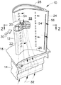
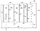
図1に示すのは、ターボファン式航空機エンジン(図示せず)のような従来のガスタービンエンジン内で用いるガスタービンロータブレード10である。ブレード自体は、一般的に従来の鋳造法を用いて製造され、プラットホーム16において支持ダブテール14に一体形に結合された翼形部12を含む。
Illustrated in FIG. 1 is a gas
翼形部は、翼弦方向に対向する前縁及び後縁22、24において互いに一体形に接合されたほぼ凹面形の正圧側壁18と円周方向に対向するほぼ凸面形の負圧側壁20とを含む。翼形部はまた、プラットホーム16における半径方向内側根元26から半径方向に対向する先端28まで長手方向又は半径方向に延びる。
The airfoil portion includes a substantially concave
運転時、ブレードは、ダブテール14を相補形のダブテールスロットに捕捉することによって支持ロータディスク(図示せず)内に取付けられる。このようにして、回転作動中にブレードに発生する遠心力は、ダブテールのローブ又はタングを通して支持ロータディスクで支持される。
In operation, the blades are mounted in a support rotor disk (not shown) by capturing the
高温燃焼ガス30は、燃焼器(図示せず)内で生成されて翼形部の外面上を流れ、翼形部が、ロータディスクを回転させるためのエネルギーを燃焼ガスから取り出す。上で指摘したように、タービンロータブレードは、その耐久性及び長い有効寿命を確保するために冷却を必要とし、冷却空気32が運転時にエンジンの高圧圧縮機(図示せず)から適当に抽気される。
Hot combustion gas 30 is generated in a combustor (not shown) and flows over the outer surface of the airfoil, and the airfoil extracts energy from the combustion gas for rotating the rotor disk. As pointed out above, turbine rotor blades require cooling to ensure their durability and long useful life, and cooling
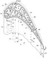
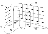
翼形部12は、図2により詳細に示しており、翼形部の内部に配置されて該翼形部の根元から先端まで長手方向に延びる複数の独立した冷却回路34、36、38を含む。例示的な3つの冷却回路は、正圧及び負圧側壁18、20に沿って対応して延び、各回路はそれ独自の独立した入口チャネル40、42、44を含む。3つの入口チャネルは、図1に示すように、翼形部内で根元から先端の直ぐ下方まで長手方向外向きに延び、かつプラットホーム及びダブテールを貫通して内向きにダブテールの底面まで延びて、エンジン圧縮機からダブテール底面に適当に導かれた加圧冷却空気32を受けるようになっている。
The
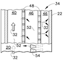
冷却回路34の第1の回路は、図2及び図3に示しており、翼形部の根元から先端まで長手方向に延びかつブリッジ48の対応する有孔隔壁によって軸方向又は翼弦方向に分離された複数のカスケード流れチャネル46を含む。各ブリッジは、それを貫通して斜めに延びる長手方向のインピンジメント孔50の列を含み、インピンジメント孔50の列は、第1の入口チャネル40を通して受けた同じ空気32を用いて翼形部の内面を順次にカスケードインピンジメント冷却する。
The first circuit of the
従って、第1のカスケード冷却回路34は、前縁の後方で翼形部の翼弦中央付近で始まり、負圧側壁20に沿って前方に延びて、前縁22の直ぐ後方又は前縁22で終わるのが好ましい。第1の回路34は、第1の入口チャネル40と好ましくは2つのカスケードチャネル46を含み、2つの対応する有孔隔壁48を有する。従って、冷却空気32は、3つのチャネルを通って順次に流れ、翼形部の半径方向スパンにわたって延びる対応するカスケード内に2つの逐次的段階のインピンジメント冷却を行い、最後に翼形部前縁22の背後を直接インピンジメント冷却する。
Thus, the first
図2及び図4に示すように、第2の冷却回路36もまた、翼形部の根元から先端まで長手方向に延びかつ対応する有孔隔壁48によって翼弦方向に分離された複数のカスケードチャネル46を含むカスケード冷却回路であるのが好ましい。それらの隔壁の各々も、同様に、翼弦方向に翼形部内面に沿って該翼形部内面をカスケードインピンジメント冷却する長手方向のインピンジメント孔50の列を含む。
2 and 4, the
図2に最も良く示すように、第1のカスケード回路34は、負圧側壁20に沿って配置されて前縁22で終わる。第2のカスケード回路36は、第1の回路の後方で正圧側壁18に沿って延びて適当に後縁24の前方で終わる。
As best shown in FIG. 2, the
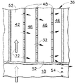
図2及び図5に示す例示的な実施形態では、第3の冷却回路38もまた、同様に構成されたカスケード冷却回路であり、翼形部の根元と先端との間で長手方向に延びかつ対応する有孔隔壁48によって翼弦方向に分離された複数のカスケード流れチャネル46を含む。それらの隔壁の各々は、翼弦方向に翼形部内面に沿って該翼形部内面をカスケードインピンジメント冷却するための長手方向のインピンジメント孔50の列を含む。
In the exemplary embodiment shown in FIGS. 2 and 5, the
図2に示す第3のカスケード回路38は、第1の回路34の後方で翼形部の翼弦中央付近で始まり、負圧側壁20に沿って延びて後縁24で終わる。従って、第2及び第3のカスケード回路36及び38は、第1のカスケード回路34の後方に配置され、翼形部の2つの対向する側面18、20に沿って並行して延びて両方とも後縁24で又は後縁24付近で終わる。
The
図2に示す第2のカスケード回路36は、3つの有孔隔壁48の対応するインピンジメント孔50を通してカスケードチャネル46の3つに順次に冷却空気32を供給するそれ自体の第2の入口チャネル42を含む。
The
これに対して、第3のカスケード回路38は、該回路の5つの有孔隔壁48の対応するインピンジメント孔50の列を通して5つのカスケードチャネル46に順次に冷却空気32を供給するそれ自体の第3の入口チャネル44を含む。
In contrast, the
従って、図2に示す単一の翼形部は、3つの独立した別個の冷却回路34、36、38を含み、それら回路の3つは全て、正圧及び負圧側壁のそれらのそれぞれの部分をカスケードインピンジメント冷却するよう構成されることが好ましい。
Thus, the single airfoil shown in FIG. 2 includes three independent and
従って、3つの冷却回路34〜38は、対応する側壁18、20に沿って対応する無孔のブリッジ又は隔壁52によって互いに分離される。無孔隔壁52は、翼形部のスパンに沿って該翼形部の根元と先端との間で延びて、3つの冷却回路を分離した状態に維持する。図2に示す第1の回路34は、前縁22の直ぐ後方の正圧側壁18から負圧側壁のハンプにおける翼形部の最大幅付近の負圧側壁20まで延びた整列しかつ同一平面にある隔壁52によって第2及び第3の回路36、38から分離される。
Thus, the three cooling circuits 34-38 are separated from each other by corresponding non-porous bridges or
これに対して、第2及び第3の冷却回路36、38は、翼形部の対向する正圧及び負圧側壁に沿って第1の回路から軸方向又は翼弦方向後方に後縁まで並行して延びて、それら回路の多数のカスケードチャネルは、翼形部がその比較的薄い後縁に向かって収束するすなわち次第に薄くなるにつれて、横幅が収束する。4つの無孔隔壁52は、翼形部の反り又は翼形中心線に沿って延びて、第2及び第3の回路を互いに対称に分離する。
In contrast, the second and
図2に示す3つの入口チャネル40〜44は、該入口チャネルと流れ連通状態で配置された対応するカスケードチャネル46に冷却空気を分配し、それらの3つの入口チャネル自体は、その領域の翼形部をインピンジメント冷却しない。
The three inlet channels 40-44 shown in FIG. 2 distribute cooling air to
しかしながら、3つの入口チャネルは、翼形部の最大幅領域内で互いにグループ分けされかつ互いに隣接して、全てがダブテールの底面の入口開口部から冷却空気32を並行して受けるのが好ましい。従って、3つの入口チャネル自体は、3つのカスケード冷却回路内に分配する前の最初に受けた冷却空気によって適切に冷却されることができる。
However, the three inlet channels are preferably grouped together and adjacent to each other within the maximum width region of the airfoil, all receiving
3つの入口チャネル40〜44は、前縁22との間に配置されたカスケードチャネル46の1つによって該前縁22から分離されるのが好ましい。例えば、第1の入口チャネル40は、第1の回路の2つのカスケードチャネル46によって前縁から分離される。第2の入口チャネル42は、第1の回路の最後のカスケードチャネル及び隣接する無孔隔壁52によって前縁22から分離される。また、第3の入口チャネル44は、第1の回路の2つのカスケードチャネル及び第2の入口チャネル42とさらに介在無孔隔壁52とによって前縁から分離される。
The three inlet channels 40-44 are preferably separated from the leading
3つの入口チャネル40〜44は、別個のカスケード回路がそれら入口チャネルから外向きに分散配置された状態で、翼形部内部で互いにグループ分けされているので、様々なインピンジメント孔50は、それぞれの有孔隔壁48を適当に傾斜して貫通して、翼形部内面の対応する部分に対して冷却空気32を斜めに衝突(インピンジメント)させる。インピンジメント孔の傾斜角度は、翼形部外面の対応する凹面形及び凸面形部分に対するそれぞれの冷却回路内の有孔隔壁の角度配向の関数として変化する。
Since the three inlet channels 40-44 are grouped together within the airfoil, with separate cascade circuits distributed outwardly from the inlet channels, the various impingement holes 50 are each The perforated
第1のインピンジメント孔50の列は、翼形部の内面に対して流入冷却空気を最初に衝突させてインピンジメント冷却効力を最大にするように、そのそれぞれの隔壁を傾斜して貫通するのが好ましい。 The rows of first impingement holes 50 incline through their respective partitions so that incoming cooling air first impinges on the airfoil inner surface to maximize impingement cooling effectiveness. Is preferred.
3つの回路の各々の第1のカスケードチャネル内の使用済みインピンジメント空気は、その後、次のインピンジメント孔の列を通して第2のすなわち次に続くカスケードチャネル内に吐出される。第2のチャネルのためのインピンジメント孔は、翼形部内面の次の部分に対する空気のインピンジメント冷却を最大にするように隔壁内で適当に傾斜している。その結果、カスケード方式では、インピンジメント孔は、冷却空気をチャネルからチャネルへと移送し、翼形部の内面の次に続く部分を繰り返しインピンジメント冷却するように隔壁内で適当に傾斜される。 Spent impingement air in the first cascade channel of each of the three circuits is then discharged through the next row of impingement holes into the second or subsequent cascade channel. The impingement holes for the second channel are suitably inclined in the septum to maximize air impingement cooling to the next portion of the airfoil inner surface. As a result, in the cascaded manner, the impingement holes are suitably tilted within the septum so as to transfer cooling air from channel to channel and repeatedly impingement cool the next portion of the airfoil inner surface.
このようにして、同じ冷却空気を順次にすなわち逐次的に使用して、3つの冷却回路の範囲に沿って翼形部の内面の対応する部分をカスケードインピンジメント冷却する。有孔及び無孔の隔壁48、52の両方は、共通に鋳造した翼形部の一体形部分であり、運転時に発生する大きな遠心荷重に耐えるような大きな強度に恵まれる。また、カスケードインピンジメント冷却は、固定タービンノズルベーンに一般的に見られるような独立したインピンジメントバッフルの必要なしに、インピンジメント冷却を普通の翼形部に導入することができる適用表面積範囲を増大するように多数の隔壁から行われる。
In this way, the same cooling air is used sequentially, i.e. sequentially, to cascade impingement cool the corresponding portion of the inner surface of the airfoil along the extent of the three cooling circuits. Both the perforated and
従って、カスケードチャネル46は、正圧側壁18又は負圧側壁20のいずれかに沿って或いは好ましい実施形態では両方に沿って前縁及び後縁22、24間で翼形部の根元から先端まで翼形部をカスケードインピンジメント冷却するように、対応する入口チャネル40〜44から順次に配置される。カスケードインピンジメント冷却は、翼形部に行うあらゆる外部冷却とは独立して、翼形部の内面の冷却を高める。
Thus, the
例えば、図2及び図3に示す負圧側壁20は、第1の回路34の最後のチャネルと流れ連通した状態で配置された1つのフィルム冷却孔54の列を含むことができる。別のフィルム冷却孔54の列もまた、正圧側壁18を貫通して第1の回路34の最後のチャネルと流れ連通した状態で配列することができる。このように、2つのフィルム冷却孔54の列は、第1の冷却回路に対して翼形部の正圧及び負圧側面に沿ってフィルムの形態で使用済みインピンジメント空気を吐出するための出口を構成して、翼形部を従来と同様にフィルム冷却する。
For example, the
同様に、図2に示す正圧側壁18は、第2の冷却回路36の最後のチャネルと流れ連通した状態で配置された別のフィルム冷却孔54の列を含むことができ、この別のフィルム冷却孔54の列は、第2の冷却回路36に対する出口を構成して該出口から下流の正圧側壁上に追加の冷却空気フィルムを形成するようにする。
Similarly, the
図2に示す第3の回路38は、後縁24に沿って任意の従来の構成で配置された、第3の回路から使用済みインピンジメント空気を吐出するための後縁出口孔56の列で終わることができる。
The
図2に示す正圧及び負圧側壁18、20は、3つの入口チャネル40〜44に沿って無孔であり、流入冷却空気の全てが3つの回路自体のカスケードチャネルを通って別々に吐出されることができるようになるのが好ましい。
The positive and
図2に示す好ましい実施形態では、正圧及び負圧側壁18、20は、上に開示した対応する出口孔54、56の列を有する対応する最後のチャネルを除いて3つのカスケード冷却回路34〜38に沿って無孔である。別の実施形態では、正圧又は負圧側壁内に或いは両方にカスケードチャネルの様々なチャネルと流れ連通した状態で追加のフィルム冷却孔の列を設けて、翼形部への熱負荷の局所的変化に適合させることができる。様々な冷却回路はまた、側壁の内面に沿って、可能な部位の熱伝達を高めるための従来型の短形リブ又はタービュレータを含むことができる。
In the preferred embodiment shown in FIG. 2, the positive and
図1〜図5に示す好ましい実施形態では、3つの冷却回路34、36、38全ては、複数のカスケードチャネル46、それらの有孔隔壁48及び対応するインピンジメント孔50の列を有するカスケードインピンジメント冷却回路の形態である。このように、インピンジメント冷却を受ける翼形部壁の内面積は、その中の隔壁及び対応する流れチャネルの数を必要以上に多くせずに最大にすることができる。
In the preferred embodiment shown in FIGS. 1-5, all three
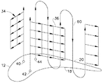
図6及び図7は、図1〜図5に示す翼形部12の変更形態を概略的に示す。図6及び図7に示す両方の実施形態では、概略的に示す第1、第2及び第3のカスケード冷却回路34、36、38は、図1〜図5におけるそれらの対応部分と同一である。しかしながら、上述のように3つの冷却回路全てがカスケード冷却回路の形態であるのではなくて、それらのカスケード回路のいずれか1つを代わりに、端部と端部とを接して配列して従来の形態の連続した蛇行チャネルを形成した冷却回路の複数の長手方向チャネルを有するように変更することができる。
6 and 7 schematically show a modification of the
より具体的には、図6に示す別の実施形態では、上述のような第1及び第3のカスケード冷却回路34、38を含み、第2のカスケード回路は、長手方向チャネルが典型的な連続した蛇行チャネルの方式で第2の入口チャネル42から端部と端部とを接して配置された蛇行冷却回路58によって置き換えられる。この構成では、2番目のカスケード回路38は、翼形部負圧側壁20に沿って配置され、また蛇行回路58は、カスケード回路38と並行して翼形部正圧側壁18に沿って配置される。
More specifically, another embodiment shown in FIG. 6 includes first and third
同様に、図7は、第1のカスケード回路34及び第2のカスケード回路36が、図1〜図5に関して上に開示したものと同一である別の実施形態を示す。第3のカスケード回路は、その長手方向チャネルが第3の入口チャネル44から端部と端部とを接して配列されて連続した蛇行チャネルを形成した別の蛇行冷却回路60によって置き換えられる。この実施形態では、第2のカスケード回路36は、翼形部正圧側壁18に沿って配置され、また蛇行チャネル60は、翼形部負圧側壁20に沿って第2のカスケード回路36と並行して配置される。
Similarly, FIG. 7 illustrates another embodiment in which the
図6の実施形態では、正圧側の蛇行チャネル58は、最後の流れチャネル内にインピンジメントの形態で冷却空気を吐出する任意の従来型構成の3経路蛇行チャネルである。図7の実施形態では、負圧側の蛇行チャネル60は、同様に最後の流れチャネル内にインピンジメントの形態で冷却空気を吐出する任意の従来型構成の5経路蛇行チャネルである。
In the embodiment of FIG. 6, the pressure
上で指摘したように、タービンロータブレード、特に第1段高圧タービンロータブレードは、燃焼器から吐出される最も高温の燃焼ガスに曝される。ロータブレードの異なった構成の正圧及び負圧側面は、運転時にその上を流れる燃焼ガスから異なった熱負荷を受ける。翼形部を上述の複数の冷却回路に分割することができることにより、翼形部の異なる部分の対応する熱負荷に対する要求に応じて翼形部の冷却効力を調整することが可能になる。 As pointed out above, turbine rotor blades, particularly first stage high pressure turbine rotor blades, are exposed to the hottest combustion gases discharged from the combustor. The different pressure and suction sides of the rotor blade are subjected to different heat loads from the combustion gas flowing thereon during operation. The ability to divide the airfoil into a plurality of cooling circuits as described above allows the airfoil cooling effectiveness to be tailored to the requirements for the corresponding thermal load of different portions of the airfoil.
カスケードインピンジメント冷却回路34〜38は、翼形部の異なる部分において、逐次的なすなわちカスケード式のインピンジメント冷却のための表面積を局所的に最大にするのが望ましい場所に用いることができる。カスケード回路は、翼形部への外部的熱負荷に適合させるのが望ましい場所で上述のような独立した蛇行冷却回路と組み合わせることができる。また、その他のタイプの従来の冷却回路を同様に上述のカスケード冷却回路の1つ又はそれ以上と共に使用して、利点を得ることができる。 Cascade impingement cooling circuits 34-38 may be used in different parts of the airfoil where it is desirable to locally maximize the surface area for sequential or cascaded impingement cooling. The cascade circuit can be combined with an independent serpentine cooling circuit as described above where it is desirable to accommodate the external heat load on the airfoil. Also, other types of conventional cooling circuits can be used with one or more of the above-described cascade cooling circuits to obtain advantages.
上で指摘したように、インピンジメント冷却は、インピンジメント空気がインピンジメントの各段階において対応するインピンジメント孔の列を通して吐出された時に大きな圧力降下を生じる。インピンジメントの次に続く段階は、冷却空気の付加的な圧力降下を生じる。また、逐次的なすなわちカスケード式のインピンジメント段階の数は、翼形部外部の燃焼ガスの局所的圧力に対する入口冷却空気の利用可能な圧力によって制限される。 As pointed out above, impingement cooling results in a large pressure drop when impingement air is discharged through the corresponding row of impingement holes at each stage of the impingement. The next stage of impingement results in an additional pressure drop of the cooling air. Also, the number of sequential or cascaded impingement stages is limited by the available pressure of the inlet cooling air relative to the local pressure of the combustion gas outside the airfoil.
図2に示す例示的な実施形態では、3つのカスケード回路は、前縁の後方で翼形部の最大幅付近で始まり、第1の回路34が前縁付近で終わり、また第2及び第3の回路36、38は後縁24付近又は後縁24で終わる。
In the exemplary embodiment shown in FIG. 2, the three cascade circuits begin behind the leading edge and near the maximum width of the airfoil, the
2段階の第1の回路34は、フィルム冷却孔54から正圧及び負圧側壁に沿って吐出される前に2回のインピンジメント空気圧力降下を受ける。
The two-stage
第2のカスケード回路36は、出口孔54から吐出される前に3つのインピンジメント冷却の段階において3回の圧力降下を受ける。また、第3のカスケード回路38は、出口孔56から吐出される前に逐次的インピンジメント冷却の段階において5回の圧力降下を受ける。
The
第2及び第3のカスケード回路36、38は、普通、翼形部後縁24付近で使用済みインピンジメント空気を吐出するので、第2及び第3のカスケード回路36、38は、この領域での燃焼ガスの外部圧力の低下の利点に恵まれて、第1の入口空気と出口空気との間の圧力降下を最大にする。
Since the second and
上述の様々なカスケードインピンジメント冷却回路は、その圧縮機がタービンロータブレードを通してのカスケードインピンジメント冷却における複数回の圧力降下に適応するのに十分な高圧冷却空気を発生する高性能ガスタービンエンジンにおいて特に有利に用いることができる。カスケードインピンジメント冷却段階の数は、設計毎で変化させて他のタイプのガスタービンエンジンにおける利用可能な圧力降下に適応させることができる。 The various cascade impingement cooling circuits described above are particularly useful in high performance gas turbine engines where the compressor generates sufficient high pressure cooling air to accommodate multiple pressure drops in cascade impingement cooling through the turbine rotor blades. It can be used advantageously. The number of cascade impingement cooling stages can vary from design to design to accommodate the available pressure drop in other types of gas turbine engines.
上述の様々なカスケード冷却回路は、そのカスケード冷却回路のために特別に構成されかつ鋳造プロセスのために互いに結合された3つのセラミックコアを用いてタービンブレードの形態で従来通りの方法で鋳造することができる。翼形部内の様々な出口孔は、ブレード自体の鋳造の後に任意の従来の穿孔法によって形成することができる。 The various cascade cooling circuits described above are cast in the conventional manner in the form of turbine blades using three ceramic cores specially configured for the cascade cooling circuit and joined together for the casting process. Can do. The various exit holes in the airfoil can be formed by any conventional drilling method after casting of the blade itself.
本明細書では本発明の好ましくかつ例示的な実施形態であると考えられるものを説明してきたが、本明細書の教示から本発明の他の変更形態が当業者には明らかになるはずであり、従って、全てのそのような変更形態は本発明の技術思想及び技術的範囲内に属するものとして特許請求の範囲で保護されることが望まれる。 While this specification has described what is considered to be preferred and exemplary embodiments of the invention, other modifications of the invention will be apparent to those skilled in the art from the teachings herein. Accordingly, all such modifications are desired to be protected by the following claims as falling within the spirit and scope of the present invention.
従って、本特許で保護されることを望むものは、特許請求の範囲に記載しかつ特定した発明である。 Accordingly, what is desired to be secured by Letters Patent is the invention as defined and identified by the following claims.
10 ガスタービンロータブレード
12 翼形部
14 支持ダブテール
16 プラットホーム
18 正圧側壁
20 負圧側壁
22 前縁
24 後縁
26 根元
28 先端
30 高温燃焼ガス
32 冷却空気
34、36、38 冷却回路
40、42、44 入口チャネル
46 カスケードチャネル
48 有孔隔壁
50 インピンジメント孔
52 無孔隔壁
54 フィルム冷却孔
56 出口孔
DESCRIPTION OF
Claims (10)
前記正圧及び負圧側壁(18、20)に沿って対応して前記翼形部内部に配置され、かつ前記ダブテール(14)を貫通した入口チャネル(40〜44)と前記側壁(18、20)を貫通して対応する出口チャネルと流れ連通した出口孔(54、56)の列とを各々が含む複数の独立した冷却回路(34〜38)と、
を含み、
前記冷却回路の1つ(34)が、前記翼形部(12)の内面をカスケードインピンジメント冷却するためのインピンジメント孔(50)の列を各々が含む対応する有孔隔壁(48)によって分離された複数のカスケードチャネル(46)を含む、
タービンブレード(10)。 Opposite positive ends coupled integrally to the support dovetail (14), joined together at the chordally opposed leading and trailing edges (22, 24) and extending longitudinally from the root (26) to the tip (28) An airfoil (12) including pressure and suction side walls (18, 20);
An inlet channel (40-44) and a side wall (18, 20) disposed within the airfoil correspondingly along the positive and negative side walls (18, 20) and passing through the dovetail (14). A plurality of independent cooling circuits (34-38) each including a row of outlet holes (54, 56) in flow communication with corresponding outlet channels through
Including
One of the cooling circuits (34) is separated by a corresponding perforated septum (48), each including a row of impingement holes (50) for cascade impingement cooling of the inner surface of the airfoil (12). A plurality of cascaded channels (46),
Turbine blade (10).
前記入口チャネル(40〜44)が、前記前縁(22)との間に配置された前記カスケードチャネル(46)の1つによって前縁から分離されている、請求項1記載のブレード。 The cooling circuits (34-38) are separated from each other along the side walls (18, 20) by a non-porous partition wall (52);
The blade according to claim 1, wherein the inlet channel (40-44) is separated from the leading edge by one of the cascade channels (46) disposed between the leading edge (22).
前記カスケードチャネル(46)が、前記対応する入口チャネル(40〜44)から前記正圧側壁(18)又は負圧側壁(20)のいずれか1つに沿って順次に配列されて、前記前縁及び後縁(22、24)間で前記側壁のいずれか1つをカスケードインピンジメント冷却するようになっている、
請求項2記載のブレード。 Each of the inlet channels (40-44) has a corresponding impingement hole (50) inclined through the perforated septum (48) and impinging cooling air against the inner surface of the airfoil at an angle. Including columns,
The cascade channel (46) is sequentially arranged from the corresponding inlet channel (40-44) along either one of the pressure side wall (18) or the suction side wall (20), and the leading edge And cascade impingement cooling any one of the side walls between the trailing edges (22, 24),
The blade according to claim 2.
前記冷却回路(36)の第2の回路が、前記正圧側壁(18)に沿って延びて前記後縁(24)の前方で終わり、
前記冷却回路(38)の第3の回路が、前記第1の冷却回路の後方でかつ前記第2の冷却回路(36)と並行して前記負圧側壁(20)に沿って延びて前記後縁(24)で終わっている、
請求項3記載のブレード。 A first circuit of the cooling circuit (34) extends along the suction side wall (20) and ends at the leading edge (22);
A second circuit of the cooling circuit (36) extends along the pressure side wall (18) and ends in front of the trailing edge (24);
A third circuit of the cooling circuit (38) extends along the suction side wall (20) behind the first cooling circuit and in parallel with the second cooling circuit (36). Ends in the rim (24),
The blade according to claim 3.
Applications Claiming Priority (1)
| Application Number | Priority Date | Filing Date | Title |
|---|---|---|---|
| US10/820,325 US7097426B2 (en) | 2004-04-08 | 2004-04-08 | Cascade impingement cooled airfoil |
Publications (1)
| Publication Number | Publication Date |
|---|---|
| JP2005299636A true JP2005299636A (en) | 2005-10-27 |
Family
ID=34912716
Family Applications (1)
| Application Number | Title | Priority Date | Filing Date |
|---|---|---|---|
| JP2005030720A Pending JP2005299636A (en) | 2004-04-08 | 2005-02-07 | Cascade impingement cooled airfoil |
Country Status (3)
| Country | Link |
|---|---|
| US (1) | US7097426B2 (en) |
| EP (1) | EP1584790A2 (en) |
| JP (1) | JP2005299636A (en) |
Cited By (5)
| Publication number | Priority date | Publication date | Assignee | Title |
|---|---|---|---|---|
| JP2007146842A (en) * | 2005-11-28 | 2007-06-14 | Snecma | Central cooling circuit for moving blades of turbomachine |
| JP2007154892A (en) * | 2005-12-05 | 2007-06-21 | General Electric Co <Ge> | Parallel meander cooling blade |
| WO2007094212A1 (en) * | 2006-02-14 | 2007-08-23 | Ihi Corporation | Cooling structure |
| US8079815B2 (en) | 2007-07-31 | 2011-12-20 | Mitsubishi Heavy Industries, Ltd. | Turbine blade |
| WO2012124578A1 (en) * | 2011-03-11 | 2012-09-20 | 株式会社Ihi | Turbine blade |
Families Citing this family (59)
| Publication number | Priority date | Publication date | Assignee | Title |
|---|---|---|---|---|
| FR2887287B1 (en) * | 2005-06-21 | 2007-09-21 | Snecma Moteurs Sa | COOLING CIRCUITS FOR MOBILE TURBINE DRIVE |
| US7293961B2 (en) * | 2005-12-05 | 2007-11-13 | General Electric Company | Zigzag cooled turbine airfoil |
| EP1881157B1 (en) | 2006-07-18 | 2014-02-12 | United Technologies Corporation | Serpentine microcircuits for local heat removal |
| US7780413B2 (en) * | 2006-08-01 | 2010-08-24 | Siemens Energy, Inc. | Turbine airfoil with near wall inflow chambers |
| US7549843B2 (en) * | 2006-08-24 | 2009-06-23 | Siemens Energy, Inc. | Turbine airfoil cooling system with axial flowing serpentine cooling chambers |
| US7625178B2 (en) * | 2006-08-30 | 2009-12-01 | Honeywell International Inc. | High effectiveness cooled turbine blade |
| GB2443638B (en) * | 2006-11-09 | 2008-11-26 | Rolls Royce Plc | An air-cooled aerofoil |
| US7690892B1 (en) * | 2006-11-16 | 2010-04-06 | Florida Turbine Technologies, Inc. | Turbine airfoil with multiple impingement cooling circuit |
| US7674093B2 (en) * | 2006-12-19 | 2010-03-09 | General Electric Company | Cluster bridged casting core |
| US7914257B1 (en) | 2007-01-17 | 2011-03-29 | Florida Turbine Technologies, Inc. | Turbine rotor blade with spiral and serpentine flow cooling circuit |
| US7780415B2 (en) * | 2007-02-15 | 2010-08-24 | Siemens Energy, Inc. | Turbine blade having a convergent cavity cooling system for a trailing edge |
| US7862299B1 (en) * | 2007-03-21 | 2011-01-04 | Florida Turbine Technologies, Inc. | Two piece hollow turbine blade with serpentine cooling circuits |
| US7901181B1 (en) * | 2007-05-02 | 2011-03-08 | Florida Turbine Technologies, Inc. | Turbine blade with triple spiral serpentine flow cooling circuits |
| US7854591B2 (en) * | 2007-05-07 | 2010-12-21 | Siemens Energy, Inc. | Airfoil for a turbine of a gas turbine engine |
| US8210814B2 (en) * | 2008-06-18 | 2012-07-03 | General Electric Company | Crossflow turbine airfoil |
| US8070442B1 (en) * | 2008-10-01 | 2011-12-06 | Florida Turbine Technologies, Inc. | Turbine airfoil with near wall cooling |
| US8167558B2 (en) * | 2009-01-19 | 2012-05-01 | Siemens Energy, Inc. | Modular serpentine cooling systems for turbine engine components |
| US8061990B1 (en) * | 2009-03-13 | 2011-11-22 | Florida Turbine Technologies, Inc. | Turbine rotor blade with low cooling flow |
| GB0905736D0 (en) | 2009-04-03 | 2009-05-20 | Rolls Royce Plc | Cooled aerofoil for a gas turbine engine |
| ES2389034T3 (en) * | 2009-05-19 | 2012-10-22 | Alstom Technology Ltd | Gas turbine blade with improved cooling |
| US8398370B1 (en) * | 2009-09-18 | 2013-03-19 | Florida Turbine Technologies, Inc. | Turbine blade with multi-impingement cooling |
| US8585365B1 (en) * | 2010-04-13 | 2013-11-19 | Florida Turbine Technologies, Inc. | Turbine blade with triple pass serpentine cooling |
| US9022736B2 (en) | 2011-02-15 | 2015-05-05 | Siemens Energy, Inc. | Integrated axial and tangential serpentine cooling circuit in a turbine airfoil |
| US9017025B2 (en) | 2011-04-22 | 2015-04-28 | Siemens Energy, Inc. | Serpentine cooling circuit with T-shaped partitions in a turbine airfoil |
| US8840363B2 (en) | 2011-09-09 | 2014-09-23 | Siemens Energy, Inc. | Trailing edge cooling system in a turbine airfoil assembly |
| US8882448B2 (en) | 2011-09-09 | 2014-11-11 | Siemens Aktiengesellshaft | Cooling system in a turbine airfoil assembly including zigzag cooling passages interconnected with radial passageways |
| US9033652B2 (en) | 2011-09-30 | 2015-05-19 | General Electric Company | Method and apparatus for cooling gas turbine rotor blades |
| US8840370B2 (en) | 2011-11-04 | 2014-09-23 | General Electric Company | Bucket assembly for turbine system |
| US9314838B2 (en) * | 2012-09-28 | 2016-04-19 | Solar Turbines Incorporated | Method of manufacturing a cooled turbine blade with dense cooling fin array |
| US9995148B2 (en) | 2012-10-04 | 2018-06-12 | General Electric Company | Method and apparatus for cooling gas turbine and rotor blades |
| US8985949B2 (en) | 2013-04-29 | 2015-03-24 | Siemens Aktiengesellschaft | Cooling system including wavy cooling chamber in a trailing edge portion of an airfoil assembly |
| GB201314222D0 (en) | 2013-08-08 | 2013-09-25 | Rolls Royce Plc | Aerofoil |
| US9528381B2 (en) * | 2013-12-30 | 2016-12-27 | General Electric Company | Structural configurations and cooling circuits in turbine blades |
| US10494929B2 (en) * | 2014-07-24 | 2019-12-03 | United Technologies Corporation | Cooled airfoil structure |
| US10605094B2 (en) | 2015-01-21 | 2020-03-31 | United Technologies Corporation | Internal cooling cavity with trip strips |
| WO2016122483A1 (en) * | 2015-01-28 | 2016-08-04 | Siemens Aktiengesellschaft | Turbine airfoil with trailing edge impingement cooling system |
| US10024171B2 (en) * | 2015-12-09 | 2018-07-17 | General Electric Company | Article and method of cooling an article |
| US10119405B2 (en) | 2015-12-21 | 2018-11-06 | General Electric Company | Cooling circuit for a multi-wall blade |
| US10053989B2 (en) | 2015-12-21 | 2018-08-21 | General Electric Company | Cooling circuit for a multi-wall blade |
| US10060269B2 (en) | 2015-12-21 | 2018-08-28 | General Electric Company | Cooling circuits for a multi-wall blade |
| US10196905B2 (en) * | 2016-02-18 | 2019-02-05 | Solar Turbines Incorporated | Airfoil for turbomachine and method of cooling same |
| US10208606B2 (en) * | 2016-02-29 | 2019-02-19 | Solar Turbine Incorporated | Airfoil for turbomachine and airfoil cooling method |
| US10415396B2 (en) | 2016-05-10 | 2019-09-17 | General Electric Company | Airfoil having cooling circuit |
| US10731472B2 (en) | 2016-05-10 | 2020-08-04 | General Electric Company | Airfoil with cooling circuit |
| US10358928B2 (en) | 2016-05-10 | 2019-07-23 | General Electric Company | Airfoil with cooling circuit |
| US10227877B2 (en) | 2016-08-18 | 2019-03-12 | General Electric Company | Cooling circuit for a multi-wall blade |
| US10267162B2 (en) | 2016-08-18 | 2019-04-23 | General Electric Company | Platform core feed for a multi-wall blade |
| US10208608B2 (en) | 2016-08-18 | 2019-02-19 | General Electric Company | Cooling circuit for a multi-wall blade |
| US10208607B2 (en) | 2016-08-18 | 2019-02-19 | General Electric Company | Cooling circuit for a multi-wall blade |
| US10221696B2 (en) | 2016-08-18 | 2019-03-05 | General Electric Company | Cooling circuit for a multi-wall blade |
| FR3067388B1 (en) | 2017-04-10 | 2020-01-17 | Safran | BLADE WITH IMPROVED COOLING CIRCUIT |
| EP3658751B1 (en) | 2017-09-25 | 2021-07-07 | Siemens Energy Global GmbH & Co. KG | Blade for a turbine blade |
| US11002138B2 (en) | 2017-12-13 | 2021-05-11 | Solar Turbines Incorporated | Turbine blade cooling system with lower turning vane bank |
| US11149550B2 (en) | 2019-02-07 | 2021-10-19 | Raytheon Technologies Corporation | Blade neck transition |
| US11459897B2 (en) * | 2019-05-03 | 2022-10-04 | Raytheon Technologies Corporation | Cooling schemes for airfoils for gas turbine engines |
| US11220912B2 (en) * | 2020-04-16 | 2022-01-11 | Raytheon Technologies Corporation | Airfoil with y-shaped rib |
| EP3954863A1 (en) * | 2020-08-10 | 2022-02-16 | Raytheon Technologies Corporation | Blade neck transition |
| KR102356488B1 (en) | 2020-08-21 | 2022-02-07 | 두산중공업 주식회사 | Turbine vane and gas turbine comprising the same |
| US12196095B2 (en) * | 2022-11-29 | 2025-01-14 | Rtx Corporation | Gas turbine engine component having an airfoil with internal cross-ribs |
Citations (6)
| Publication number | Priority date | Publication date | Assignee | Title |
|---|---|---|---|---|
| JPS60192804A (en) * | 1984-03-13 | 1985-10-01 | Toshiba Corp | Gas turbine blade |
| JPS60198305A (en) * | 1984-03-23 | 1985-10-07 | Agency Of Ind Science & Technol | Cooling structure of gas turbine moving blade |
| JPH04123301U (en) * | 1991-04-23 | 1992-11-09 | 石川島播磨重工業株式会社 | Air-cooled turbine blade structure |
| JPH0742504A (en) * | 1991-09-02 | 1995-02-10 | General Electric Co <Ge> | Turbine blade airfoil for in-line impingement cooling through lumen-forming ribs |
| JP2000161003A (en) * | 1998-11-16 | 2000-06-13 | General Electric Co <Ge> | Series impingement cooling airfoil |
| JP2002242607A (en) * | 2001-02-20 | 2002-08-28 | Mitsubishi Heavy Ind Ltd | Gas turbine cooling vane |
Family Cites Families (16)
| Publication number | Priority date | Publication date | Assignee | Title |
|---|---|---|---|---|
| GB1605194A (en) * | 1974-10-17 | 1983-04-07 | Rolls Royce | Rotor blade for gas turbine engines |
| US4770608A (en) * | 1985-12-23 | 1988-09-13 | United Technologies Corporation | Film cooled vanes and turbines |
| US5720431A (en) * | 1988-08-24 | 1998-02-24 | United Technologies Corporation | Cooled blades for a gas turbine engine |
| US5165852A (en) * | 1990-12-18 | 1992-11-24 | General Electric Company | Rotation enhanced rotor blade cooling using a double row of coolant passageways |
| US5813835A (en) * | 1991-08-19 | 1998-09-29 | The United States Of America As Represented By The Secretary Of The Air Force | Air-cooled turbine blade |
| US5246340A (en) * | 1991-11-19 | 1993-09-21 | Allied-Signal Inc. | Internally cooled airfoil |
| US5690472A (en) * | 1992-02-03 | 1997-11-25 | General Electric Company | Internal cooling of turbine airfoil wall using mesh cooling hole arrangement |
| US5660524A (en) * | 1992-07-13 | 1997-08-26 | General Electric Company | Airfoil blade having a serpentine cooling circuit and impingement cooling |
| US5356265A (en) * | 1992-08-25 | 1994-10-18 | General Electric Company | Chordally bifurcated turbine blade |
| US5690473A (en) * | 1992-08-25 | 1997-11-25 | General Electric Company | Turbine blade having transpiration strip cooling and method of manufacture |
| US5387085A (en) * | 1994-01-07 | 1995-02-07 | General Electric Company | Turbine blade composite cooling circuit |
| US5626462A (en) * | 1995-01-03 | 1997-05-06 | General Electric Company | Double-wall airfoil |
| US5498133A (en) * | 1995-06-06 | 1996-03-12 | General Electric Company | Pressure regulated film cooling |
| US6126396A (en) * | 1998-12-09 | 2000-10-03 | General Electric Company | AFT flowing serpentine airfoil cooling circuit with side wall impingement cooling chambers |
| US6402471B1 (en) * | 2000-11-03 | 2002-06-11 | General Electric Company | Turbine blade for gas turbine engine and method of cooling same |
| US6554563B2 (en) * | 2001-08-13 | 2003-04-29 | General Electric Company | Tangential flow baffle |
-
2004
- 2004-04-08 US US10/820,325 patent/US7097426B2/en not_active Expired - Fee Related
-
2005
- 2005-02-01 EP EP05250524A patent/EP1584790A2/en not_active Withdrawn
- 2005-02-07 JP JP2005030720A patent/JP2005299636A/en active Pending
Patent Citations (6)
| Publication number | Priority date | Publication date | Assignee | Title |
|---|---|---|---|---|
| JPS60192804A (en) * | 1984-03-13 | 1985-10-01 | Toshiba Corp | Gas turbine blade |
| JPS60198305A (en) * | 1984-03-23 | 1985-10-07 | Agency Of Ind Science & Technol | Cooling structure of gas turbine moving blade |
| JPH04123301U (en) * | 1991-04-23 | 1992-11-09 | 石川島播磨重工業株式会社 | Air-cooled turbine blade structure |
| JPH0742504A (en) * | 1991-09-02 | 1995-02-10 | General Electric Co <Ge> | Turbine blade airfoil for in-line impingement cooling through lumen-forming ribs |
| JP2000161003A (en) * | 1998-11-16 | 2000-06-13 | General Electric Co <Ge> | Series impingement cooling airfoil |
| JP2002242607A (en) * | 2001-02-20 | 2002-08-28 | Mitsubishi Heavy Ind Ltd | Gas turbine cooling vane |
Cited By (7)
| Publication number | Priority date | Publication date | Assignee | Title |
|---|---|---|---|---|
| JP2007146842A (en) * | 2005-11-28 | 2007-06-14 | Snecma | Central cooling circuit for moving blades of turbomachine |
| JP2007154892A (en) * | 2005-12-05 | 2007-06-21 | General Electric Co <Ge> | Parallel meander cooling blade |
| WO2007094212A1 (en) * | 2006-02-14 | 2007-08-23 | Ihi Corporation | Cooling structure |
| US8172505B2 (en) | 2006-02-14 | 2012-05-08 | Ihi Corporation | Cooling structure |
| US8079815B2 (en) | 2007-07-31 | 2011-12-20 | Mitsubishi Heavy Industries, Ltd. | Turbine blade |
| WO2012124578A1 (en) * | 2011-03-11 | 2012-09-20 | 株式会社Ihi | Turbine blade |
| JP2012189026A (en) * | 2011-03-11 | 2012-10-04 | Ihi Corp | Turbine blade |
Also Published As
| Publication number | Publication date |
|---|---|
| US20050226726A1 (en) | 2005-10-13 |
| US7097426B2 (en) | 2006-08-29 |
| EP1584790A2 (en) | 2005-10-12 |
Similar Documents
| Publication | Publication Date | Title |
|---|---|---|
| JP2005299636A (en) | Cascade impingement cooled airfoil | |
| US7296973B2 (en) | Parallel serpentine cooled blade | |
| CA2477402C (en) | Converging pin cooled airfoil | |
| US6099252A (en) | Axial serpentine cooled airfoil | |
| US6832889B1 (en) | Integrated bridge turbine blade | |
| CA2668605C (en) | Crossflow turbine airfoil | |
| US7011502B2 (en) | Thermal shield turbine airfoil | |
| US6554563B2 (en) | Tangential flow baffle | |
| US7293961B2 (en) | Zigzag cooled turbine airfoil | |
| JP4453826B2 (en) | 3-circuit turbine blade | |
| CN1987055B (en) | Counter-cooled turbine nozzle | |
| US6382908B1 (en) | Nozzle fillet backside cooling | |
| JP2005180422A (en) | Two cooling medium type turbine blade | |
| US6183198B1 (en) | Airfoil isolated leading edge cooling | |
| JP2006037957A (en) | Common tip chamber blade |
Legal Events
| Date | Code | Title | Description |
|---|---|---|---|
| A621 | Written request for application examination |
Free format text: JAPANESE INTERMEDIATE CODE: A621 Effective date: 20080131 |
|
| A977 | Report on retrieval |
Free format text: JAPANESE INTERMEDIATE CODE: A971007 Effective date: 20100421 |
|
| A131 | Notification of reasons for refusal |
Free format text: JAPANESE INTERMEDIATE CODE: A131 Effective date: 20100427 |
|
| A601 | Written request for extension of time |
Free format text: JAPANESE INTERMEDIATE CODE: A601 Effective date: 20100723 |
|
| RD02 | Notification of acceptance of power of attorney |
Free format text: JAPANESE INTERMEDIATE CODE: A7422 Effective date: 20100723 |
|
| RD04 | Notification of resignation of power of attorney |
Free format text: JAPANESE INTERMEDIATE CODE: A7424 Effective date: 20100723 |
|
| A602 | Written permission of extension of time |
Free format text: JAPANESE INTERMEDIATE CODE: A602 Effective date: 20100728 |
|
| A521 | Written amendment |
Free format text: JAPANESE INTERMEDIATE CODE: A523 Effective date: 20101026 |
|
| A02 | Decision of refusal |
Free format text: JAPANESE INTERMEDIATE CODE: A02 Effective date: 20110208 |