JP2005299610A - Water pump - Google Patents
Water pump Download PDFInfo
- Publication number
- JP2005299610A JP2005299610A JP2004121039A JP2004121039A JP2005299610A JP 2005299610 A JP2005299610 A JP 2005299610A JP 2004121039 A JP2004121039 A JP 2004121039A JP 2004121039 A JP2004121039 A JP 2004121039A JP 2005299610 A JP2005299610 A JP 2005299610A
- Authority
- JP
- Japan
- Prior art keywords
- coolant
- rolling bearing
- inner ring
- rotating member
- seal
- Prior art date
- Legal status (The legal status is an assumption and is not a legal conclusion. Google has not performed a legal analysis and makes no representation as to the accuracy of the status listed.)
- Pending
Links
Images
Landscapes
- Structures Of Non-Positive Displacement Pumps (AREA)
Abstract
Description
本発明は、自動車等の内燃機関を冷却するためのウォータポンプに関し、更に詳しくは、インペラが取り付けられるシャフト部とベルトが巻き掛けられるプーリ部とが一体化された金属プレス製の回転部材を用いたタイプのウォータポンプに関する。 The present invention relates to a water pump for cooling an internal combustion engine such as an automobile, and more specifically, uses a rotating member made of a metal press in which a shaft portion to which an impeller is attached and a pulley portion to which a belt is wound are integrated. Related to the type of water pump.
自動車のエンジンを冷却すべくクーラントを循環させるウォータポンプとして、従来、図3に断面図を例示するように、インペラ31が取り付けられるシャフト部321と、ベルト33が巻き掛けられるプーリ部322とが一体に形成された金属プレス製の回転部材32を、インペラ31が収容される水室341を備えたボディ34に対して転がり軸受35を介して回転自在に支持するとともに、ボディ34と回転部材32のシャフト部321との間をメカニカルシール36で封止した構造のものが知られている(例えば特許文献1参照)。
Conventionally, as a water pump for circulating coolant to cool an automobile engine, a
この構造のウォータポンプにおいては、通常、図示のように円筒部を備えた支持部材342をボディ34に一体に設け、この支持部材342の円筒部の外周面に転がり軸受35の内輪351を圧入するとともに、回転部材32のプーリ部322の内側に形成されている円筒部322aに転がり軸受35の外輪352の外周面が圧入される。
In the water pump having this structure, a
組立てに際しては、通常、回転部材32に転がり軸受35を組み付けたものを、支持部材342対して組み付けた後、インペラ31をシャフト部321に固着したうえで、支持部材342をボディ34に取り付ける方法が採られる。すなわち、回転部材32のプーリ部322を転がり軸受35の外輪352に嵌め込んで一体化した後、転がり軸受35の内輪351を支持部材342に対して圧入して一体化する。この圧入に際しては、圧入治具等を用いて内輪351を支持部材342に対して相応の力で押し込む必要があり、この圧入作業のために、回転部材32のシャフト部321の付け根部分に、内輪351の一端面を臨むように複数の孔323が設けられる。また、これらの孔323は、水室341内のクーラントがメカニカルシール36を通って外部に若干量だけ漏れた場合に、転がり軸受35の回転等により発生する熱などで蒸発して蒸気となって逃がすための通路としても機能する。
When assembling, there is usually a method in which the rolling member 35 assembled to the rotating
また、この種のウォータポンプに用いられる転がり軸受35は、グリース封入タイプの通常の玉軸受などが用いられる。すなわち、内輪351と外輪352、これらの間に転動自在に配置されたボール353、各ボール353を周方向に一定のピッチで保持する保持器354を備えるとともに、軸方向両端部にはシール355を備えた構造をとり、各シール355は、外輪352の両端部内側に設けられたシール溝352aに対してその外周部が固定され、内周部に設けられたリップ部355aが内輪351に摺動接触して、内部に設けられたグリースの漏出を防止すると同時に、外部からの異物や水等の侵入を防止する役割を担っている。
ところで、自動車のエンジンを冷却するクーラントには、一般に、防錆や凍結防止等を目的として、水に対してエチレングリコール等が添加される場合が多い。このクーラントに含まれるエチレングリコールが、長期の使用やその他の原因によって、メカニカルシール36を通って漏れた後に凝固し、図4に図3のA部拡大図を示すように、この凝固物Sがシャフト部321の付け根部分に形成されている孔323を塞いでしまう場合がある。この場合、メカニカルシール36を通過してシャフト部321を伝ってきたクーラントは、転がり軸受35の内輪351の一端側のCで示される部位に滞ることになる。
By the way, in general, an ethylene glycol or the like is often added to water for cooling an automobile engine for the purpose of preventing rust or preventing freezing. The ethylene glycol contained in this coolant is solidified after leaking through the
この状態においては、転がり軸受35のシール355のリップ部355aがクーラントに浸漬した状態となり、転がり軸受35の内部にクーラントが侵入し、転がり軸受35の破損の原因となる場合もあるという問題がある。この現象は、孔323が塞がれなくても、メカニカルシール36から大量のクーラントが漏れた場合にも生じる。
In this state, the
本発明はこのような実情に鑑みてなされたもので、クーラントを外部に排出するための孔が塞がれたり、メカニカルシールから大量のクーラントが漏れても、そのクーラントが転がり軸受に侵入することを防止することのできるウォータポンプの提供をその課題としている。 The present invention has been made in view of such circumstances, and even if a hole for discharging the coolant to the outside is blocked or a large amount of coolant leaks from the mechanical seal, the coolant will roll into the rolling bearing. The problem is to provide a water pump that can prevent the above.
上記の課題を解決するため、本発明のウォータポンプは、インペラが取り付けられるシャフト部とベルトが巻き掛けられるプーリ部とが一体化された金属プレス成形体からなる回転部材を、上記インペラを収容する水室が形成されたボディに対して転がり軸受を介して回転自在に支持するとともに、その転がり軸受は、上記ボディに形成された円筒部外周面に内輪が圧入固定され、上記回転部材のプーリブの内側に形成された円筒部に外輪画集面が圧入固定されるウォータポンプにおいて、上記転がり軸受の両端部に、それぞれ内周部が内輪に固定され、かつ、外周部が外輪に対して摺動接触するシールが装着されていることによって特徴づけられる。 In order to solve the above-described problems, a water pump according to the present invention accommodates a rotating member made of a metal press-molded body in which a shaft portion to which an impeller is attached and a pulley portion on which a belt is wound is integrated. The rolling bearing is supported rotatably via a rolling bearing on the body in which the water chamber is formed, and the inner ring is press-fitted and fixed to the outer peripheral surface of the cylindrical portion formed in the body, and the pulley of the rotating member is In the water pump in which the outer ring drawing surface is press-fitted and fixed to the cylindrical part formed inside, the inner peripheral part is fixed to the inner ring at both ends of the rolling bearing, and the outer peripheral part is in sliding contact with the outer ring. It is characterized by the fact that a seal is attached.
本発明は、メカニカルシールを通過したクーラントが滞りやすい部位に転がり軸受のシールのリップ部を設けず、この部位にはシールの転がり軸受への固定部を設けることによって、所期の課題を解決しようとするものである。 The present invention solves the intended problem by not providing the lip portion of the rolling bearing seal at the portion where the coolant that has passed through the mechanical seal is likely to stagnate, and by providing the fixing portion of the seal to the rolling bearing at this portion. It is what.
すなわち、メカニカルシールを通過したクーラントが転がり軸受内部に侵入するのは、前記したように、滞ったクーラント内にシールのリップ部が浸漬された状態となるためであり、クーラントが滞りやすいのは内輪の近傍である。そこで、転がり軸受のシールの内周側を内輪に対して固定し、外周側に外輪に対して摺動接触するリップ部を設けることにより、クーラントが滞ってもリップ部が浸漬されることなく、内輪に対する固定部が浸漬された状態となる。シールの液体に対するシール性能は、一般に、リップ部に比して固定部が圧倒的に良好であるため、クーラントの転がり軸受への侵入を可及的に少なくすることができる。 In other words, the coolant that has passed through the mechanical seal rolls and enters the inside of the bearing, as described above, because the lip portion of the seal is immersed in the stagnant coolant. It is the neighborhood. Therefore, by fixing the inner peripheral side of the seal of the rolling bearing to the inner ring and providing a lip part that is in sliding contact with the outer ring on the outer peripheral side, the lip part is not immersed even if the coolant stagnates, The fixed part with respect to the inner ring is immersed. In general, the sealing performance with respect to the liquid of the seal is overwhelmingly better than that of the lip portion, so that the penetration of the coolant into the rolling bearing can be minimized.
本発明によれば、回転部材に形成されたクーラントを逃がすための孔が塞がれたり、あるいはメカニカルシールから大量のクーラントが漏れた場合でも、転がり軸受内へのクーラントの侵入を有効に防止することができる。しかも、このクーラントの侵入を防止するために別途シールなどの部材を追加する必要がないため、本発明の適用によるコストアップも生じない。 According to the present invention, even when a hole for releasing the coolant formed in the rotating member is blocked or a large amount of coolant leaks from the mechanical seal, the coolant is effectively prevented from entering the rolling bearing. be able to. In addition, it is not necessary to add a separate member such as a seal in order to prevent the coolant from entering, so that the cost increase due to the application of the present invention does not occur.
以下、図面を参照しつつ本発明の実施の形態について説明する。
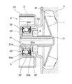
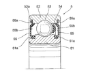
図1は本発明の実施の形態の要部断面図であり、図2はその転がり軸受5の詳細構造を示す軸平行断面図である。
Hereinafter, embodiments of the present invention will be described with reference to the drawings.
FIG. 1 is a cross-sectional view of an essential part of an embodiment of the present invention, and FIG. 2 is an axial parallel cross-sectional view showing a detailed structure of the rolling bearing 5.
この例においては、ウォータポンプの基本的構成は図3に示したものと同等であり、 インペラ1が装着されるシャフト部21と、ベルト3が巻き掛けられるプーリ部22とが一体に形成された金属プレス成形体からなる回転部材2、インペラ1を収容する水室41が形成され、かつ、転がり軸受5の内輪51が圧入される円筒部を有する支持部材42が一体化されたボディ4、および水室41内のクーラントの漏れを防止するためのメカニカルシール6を主体として構成されている。
In this example, the basic configuration of the water pump is the same as that shown in FIG. 3, and the
転がり軸受5は、内輪51、外輪52、複数のボール53、各ボール53を周方向に一定のピッチで保持する保持器54、および両端部に装着されるシール55からなり、上記のように内輪51の内周面が支持部材42の円筒部に圧入されているとともに、回転部材2のプーリ部22の内側に形成されている円筒部22aに外輪52の外周面が圧入され、これにより回転部材2がボディ4に対して回転自在に支持されている。
The rolling
回転部材2のシャフト部21の付け根部分には、図3の例と同様に複数の孔23が形成されており、転がり軸受5の外輪52に回転部材2を装着してこれらを一体化した後、孔23を介して圧入治具で内輪51を押圧することによって、内輪51を支持部材42の円筒部に圧入して三者を一体化するとともに、シャフト部21にインペラ1を固定した後、支持部材42をボディ4に固定することによって組み立てられる。また、孔23はメカニカルシール6を介して漏出したクーラントの逃がし孔としても機能することも、図3に示した従来のものと同様である。
A plurality of
さて、この実施の形態の特徴は、転がり軸受5のシール55が、内輪固定/外輪摺動接触となっている点である。すなわち、図2に示すように、内輪51の両端部外周にシール溝51aが形成されており、各シール55はその内周部がこのシール溝51aに対して嵌め込まれて固定されている。各シール55の外周部にはリップ部55aが形成されており、このリップ部55aが外輪52の内周面と、外輪52の両端部に形成された溝52aの側端部に摺動接触する。なお、55bは芯金である。
The feature of this embodiment is that the
以上の本発明の実施の形態によると、メカニカルシール6を通過したクーラントに含まれるエチレングリコールが凝固して孔23が塞がれ、これによって前記した図4にCで示した部位にクーラントが滞っても、あるいはメカニカルシール6を通じて大量のクーラントが漏れても、シール55の内輪51に対する固定部がクーラント内に浸漬されるものの外輪52に対する摺動接触部は浸漬されないため、摺動接触部を通じてクーラントが転がり軸受5内に侵入することがない。その結果、転がり軸受5が長期にわたって安定した性能を発揮することができる。
According to the above-described embodiment of the present invention, ethylene glycol contained in the coolant that has passed through the
なお、本発明は、インペラ1や回転部材2、およびボディ4の形状等については、上記した実施の形態で示したものに限られることなく、この種のウォータポンプで用いられている公知の形状等を採用し得ることは勿論である。また、シール55のリップ部55aの形状等についても、他の公知の形状等を採用し得ることは言うまでもない。
In the present invention, the shape of the impeller 1, the rotating
1 インペラ
2 回転部材
21 シャフト部
22 プーリ部
23 孔
3 ベルト
4 ボディ
41 水室
42 支持部材
5 転がり軸受
51 内輪
51a シール溝
52 外輪
52a 溝
53 ボール
54 保持器
55 シール
55a リップ部
DESCRIPTION OF SYMBOLS 1
Claims (1)
上記転がり軸受の両端部に、それぞれ内周部が内輪に固定され、かつ、外周部が外輪に対して摺動接触するシールが装着されていることを特徴とするウォータポンプ。 A rotating member made of metal press, in which a shaft portion to which an impeller is attached and a pulley portion around which a belt is wound, is integrated, is rotatable via a rolling bearing with respect to a body in which a water chamber for housing the impeller is formed. The inner ring is press-fitted and fixed to the outer peripheral surface of the cylindrical part formed on the body, and the outer peripheral surface of the outer ring is press-fitted and fixed to the cylindrical part formed inside the pulley part of the rotating member. In the water pump,
A water pump characterized in that inner ends of the rolling bearings are fixed to the inner ring, and seals are mounted so that the outer peripheral portion is in sliding contact with the outer ring.
Priority Applications (1)
| Application Number | Priority Date | Filing Date | Title |
|---|---|---|---|
| JP2004121039A JP2005299610A (en) | 2004-04-16 | 2004-04-16 | Water pump |
Applications Claiming Priority (1)
| Application Number | Priority Date | Filing Date | Title |
|---|---|---|---|
| JP2004121039A JP2005299610A (en) | 2004-04-16 | 2004-04-16 | Water pump |
Publications (1)
| Publication Number | Publication Date |
|---|---|
| JP2005299610A true JP2005299610A (en) | 2005-10-27 |
Family
ID=35331446
Family Applications (1)
| Application Number | Title | Priority Date | Filing Date |
|---|---|---|---|
| JP2004121039A Pending JP2005299610A (en) | 2004-04-16 | 2004-04-16 | Water pump |
Country Status (1)
| Country | Link |
|---|---|
| JP (1) | JP2005299610A (en) |
Cited By (4)
| Publication number | Priority date | Publication date | Assignee | Title |
|---|---|---|---|---|
| JP2009074479A (en) * | 2007-09-21 | 2009-04-09 | Jtekt Corp | Water pump |
| JP2009074480A (en) * | 2007-09-21 | 2009-04-09 | Jtekt Corp | Water pump |
| CN102102576A (en) * | 2009-12-18 | 2011-06-22 | 日立汽车系统株式会社 | Water pump for motor vehicle and bearing structure |
| CN110873122A (en) * | 2019-11-26 | 2020-03-10 | 柳州上汽汽车变速器有限公司 | Speed changer bearing |
Citations (2)
| Publication number | Priority date | Publication date | Assignee | Title |
|---|---|---|---|---|
| JPH0329724U (en) * | 1989-08-01 | 1991-03-25 | ||
| JP2002089486A (en) * | 2000-09-19 | 2002-03-27 | Aisin Seiki Co Ltd | Water pump |
-
2004
- 2004-04-16 JP JP2004121039A patent/JP2005299610A/en active Pending
Patent Citations (2)
| Publication number | Priority date | Publication date | Assignee | Title |
|---|---|---|---|---|
| JPH0329724U (en) * | 1989-08-01 | 1991-03-25 | ||
| JP2002089486A (en) * | 2000-09-19 | 2002-03-27 | Aisin Seiki Co Ltd | Water pump |
Cited By (7)
| Publication number | Priority date | Publication date | Assignee | Title |
|---|---|---|---|---|
| JP2009074479A (en) * | 2007-09-21 | 2009-04-09 | Jtekt Corp | Water pump |
| JP2009074480A (en) * | 2007-09-21 | 2009-04-09 | Jtekt Corp | Water pump |
| CN102102576A (en) * | 2009-12-18 | 2011-06-22 | 日立汽车系统株式会社 | Water pump for motor vehicle and bearing structure |
| JP2011127539A (en) * | 2009-12-18 | 2011-06-30 | Hitachi Automotive Systems Ltd | Water pump for automobile and bearing structure |
| US8734099B2 (en) | 2009-12-18 | 2014-05-27 | Hitachi Automotive Systems, Ltd. | Water pump for vehicle and bearing structure |
| CN110873122A (en) * | 2019-11-26 | 2020-03-10 | 柳州上汽汽车变速器有限公司 | Speed changer bearing |
| CN110873122B (en) * | 2019-11-26 | 2021-04-30 | 柳州上汽汽车变速器有限公司 | Speed changer bearing |
Similar Documents
| Publication | Publication Date | Title |
|---|---|---|
| US20040067130A1 (en) | Seal apparatus for a water pump, rotation-support apparatus for a water pump, and a water pump | |
| JP5713870B2 (en) | Water pump for internal combustion engine | |
| JP2003065289A (en) | Seal device for water pump, rotation supporting device for water pump and water pump | |
| JP5563525B2 (en) | Water pump | |
| JPWO2003091573A1 (en) | Water pump seal device, water pump rotation support device, water pump assembly method | |
| JP2005299610A (en) | Water pump | |
| JP2010002017A (en) | Rolling bearing | |
| JP2008039124A (en) | Bearing unit and motor | |
| JP2009203846A (en) | Ball bearing arrangement for turbocharger | |
| JP2014190377A (en) | Bearing device | |
| JP2007321886A (en) | Ball screw device | |
| JP2007078115A (en) | Rolling bearing | |
| JP2009074480A (en) | Water pump | |
| JP2014149033A (en) | Shell-shaped needle bearing | |
| JP2012047243A (en) | Sealing device of bearing for water pump | |
| JP2011174566A (en) | Bearing | |
| JP2009024804A (en) | Sealing device | |
| JP4334502B2 (en) | Sealed rolling bearing for motor | |
| JP2011085217A (en) | Water pump bearing | |
| JP2005048780A (en) | Seal ring for water pump, rotary supporting device for water pump, and water pump | |
| JP2007146869A (en) | Rolling bearing and bearing device | |
| JP2008121503A (en) | Water pump | |
| JP2004052793A (en) | Rolling bearing | |
| JP2004270775A (en) | Sealing device for rolling bearing | |
| JP2006258247A (en) | Pulley unit |
Legal Events
| Date | Code | Title | Description |
|---|---|---|---|
| A621 | Written request for application examination |
Effective date: 20070326 Free format text: JAPANESE INTERMEDIATE CODE: A621 |
|
| A977 | Report on retrieval |
Free format text: JAPANESE INTERMEDIATE CODE: A971007 Effective date: 20100419 |
|
| A131 | Notification of reasons for refusal |
Free format text: JAPANESE INTERMEDIATE CODE: A131 Effective date: 20100519 |
|
| A02 | Decision of refusal |
Effective date: 20100922 Free format text: JAPANESE INTERMEDIATE CODE: A02 |