JP2005299544A - Fuel injection valve and control method thereof - Google Patents
Fuel injection valve and control method thereof Download PDFInfo
- Publication number
- JP2005299544A JP2005299544A JP2004118149A JP2004118149A JP2005299544A JP 2005299544 A JP2005299544 A JP 2005299544A JP 2004118149 A JP2004118149 A JP 2004118149A JP 2004118149 A JP2004118149 A JP 2004118149A JP 2005299544 A JP2005299544 A JP 2005299544A
- Authority
- JP
- Japan
- Prior art keywords
- fuel
- fuel injection
- orifice plate
- balance rod
- injection valve
- Prior art date
- Legal status (The legal status is an assumption and is not a legal conclusion. Google has not performed a legal analysis and makes no representation as to the accuracy of the status listed.)
- Pending
Links
Images

Landscapes
- Fuel-Injection Apparatus (AREA)
Abstract
【課題】 燃料噴射に伴う圧力波を減衰させることができると共に、燃料噴射率を高い応答性で制御することのできる燃料噴射弁と、その制御方法を提供する。
【解決手段】 蓄圧室から供給される高圧燃料を開閉可能な燃料噴射孔1から噴射する燃料噴射弁100において、燃料噴射弁100内に設けられている上記燃料噴射孔1へ通ずる燃料通路12内に少なくとも一つの貫通孔14aを有するオリフィスプレート14が配設されていて、該オリフィスプレート14の位置が、ほぼ総ての燃料が上記貫通孔14aを通って流れる閉位置と、燃料が上記オリフィスプレート14の外周縁部を越えて流れることが可能な開位置との間で切替えられるように構成されていることを特徴とする、燃料噴射弁と、その制御方法が提供される。
【選択図】 図1
PROBLEM TO BE SOLVED: To provide a fuel injection valve capable of attenuating a pressure wave accompanying fuel injection and controlling a fuel injection rate with high responsiveness, and a control method therefor.
In a fuel injection valve 100 for injecting a high-pressure fuel supplied from a pressure accumulating chamber through a fuel injection hole 1 that can be opened and closed, in a fuel passage 12 communicating with the fuel injection hole 1 provided in the fuel injection valve 100 Is provided with an orifice plate 14 having at least one through-hole 14a, the position of the orifice plate 14 being a closed position in which almost all of the fuel flows through the through-hole 14a, and the fuel passing through the orifice plate 14a. A fuel injection valve and a control method therefor are provided, wherein the fuel injection valve is configured to be switched between an open position capable of flowing beyond the outer peripheral edge portion of 14.
[Selection] Figure 1
Description
本発明は燃料噴射弁及びその制御方法に関し、より詳細には内燃機関用のコモンレール式(蓄圧式)燃料噴射装置に用いられる燃料噴射弁及びその制御方法に関する。 The present invention relates to a fuel injection valve and a control method thereof, and more particularly to a fuel injection valve used in a common rail type (accumulation type) fuel injection device for an internal combustion engine and a control method thereof.
高圧燃料を貯留するコモンレール(すなわち、蓄圧室)を設け、このコモンレールに各気筒の燃料噴射弁を分岐燃料配管を介して接続し、コモンレール内の高圧燃料を各燃料噴射弁に分配して各燃料噴射弁の開閉可能な燃料噴射孔から燃料噴射するようにしたコモンレール式燃料噴射装置が知られている。このようなコモンレール式燃料噴射装置では、高圧燃料ポンプからコモンレールに圧送される燃料量を制御することにより、コモンレール内圧力(すなわち各燃料噴射弁への供給燃料圧力)を機関運転状態に応じて制御することができる。 A common rail (that is, a pressure accumulating chamber) for storing high-pressure fuel is provided, and fuel injection valves of each cylinder are connected to the common rail via branch fuel pipes, and the high-pressure fuel in the common rail is distributed to each fuel injection valve. 2. Description of the Related Art A common rail fuel injection device is known in which fuel is injected from a fuel injection hole that can open and close an injection valve. In such a common rail type fuel injection device, by controlling the amount of fuel pumped from the high pressure fuel pump to the common rail, the pressure in the common rail (that is, the fuel pressure supplied to each fuel injection valve) is controlled according to the engine operating state. can do.
ところで、このようなコモンレール式燃料噴射装置においては、ある気筒に設置された燃料噴射弁の燃料噴射孔の開閉(すなわち、燃料噴射)により生じた圧力波もしくは圧力脈動(以下、単に「圧力波」という)が、分岐燃料配管内からコモンレールを伝播して他の気筒に設置された燃料噴射弁に作用する場合がある。この場合、伝播した圧力波が、他の燃料噴射弁の噴射量、あるいは噴射率等を変化させてしまうことがある。また、コモンレール式燃料噴射装置に用いられる燃料噴射弁は一般に、燃料噴射弁の内部に設けた制御室に高圧燃料を導入することで燃料噴射弁のニードル弁を下降させて燃料噴射孔を常閉状態に保ち、更に、制御室内の燃料を燃料排出通路にリークさせ、制御室内を減圧することで、ニードル弁を上昇せしめて燃料噴射孔を開き燃料噴射する構成となっている。このため、上述の圧力波が他の燃料噴射弁の噴射時期を変化させてしまう場合もある。 By the way, in such a common rail type fuel injection device, pressure waves or pressure pulsations (hereinafter simply referred to as “pressure waves”) generated by opening and closing (that is, fuel injection) of fuel injection holes of fuel injection valves installed in a certain cylinder. However, there is a case where it propagates through the common rail from the branched fuel pipe and acts on the fuel injection valve installed in the other cylinder. In this case, the propagated pressure wave may change the injection amount or the injection rate of other fuel injection valves. In general, a fuel injection valve used in a common rail type fuel injection device generally closes the fuel injection hole by lowering the needle valve of the fuel injection valve by introducing high-pressure fuel into a control chamber provided inside the fuel injection valve. In this state, the fuel in the control chamber is leaked into the fuel discharge passage, and the pressure in the control chamber is reduced to raise the needle valve, open the fuel injection hole, and inject fuel. For this reason, the above-mentioned pressure wave may change the injection timing of other fuel injection valves.
更に、燃料噴射弁の燃料噴射孔の開閉により生じた圧力波が分岐燃料配管とコモンレールとの接続部分で反射し、分岐配管内を伝播して圧力波を生じた燃料噴射弁自体に作用する場合がある。この場合、反射した圧力波が、当該燃料噴射弁の噴射量や噴射率の他、次回の開弁タイミングを狂わせてしまうこともある。 Furthermore, when the pressure wave generated by opening and closing the fuel injection hole of the fuel injection valve is reflected at the connecting portion between the branch fuel pipe and the common rail, it propagates through the branch pipe and acts on the fuel injection valve itself that generated the pressure wave There is. In this case, the reflected pressure wave may disturb the next valve opening timing in addition to the injection amount and injection rate of the fuel injection valve.
そして、このように燃料噴射弁の燃料噴射孔の開閉により生じた圧力波によって、燃料噴射弁の噴射時期、噴射量、あるいは噴射率等を含む噴射特性が変化してしまうと、精度の高い燃料噴射制御を行うことが困難になってしまう。そこで、このような燃料噴射弁への圧力波の影響を低減するために、コモンレールと各燃料噴射弁とを接続する各分岐燃料配管にオリフィスのような流路断面縮小部を設け、オリフィスの流路抵抗により圧力波を短時間で減衰させるようにした燃料噴射装置が知られている。 If the injection characteristics including the injection timing, injection amount, injection rate, etc. of the fuel injection valve change due to the pressure wave generated by opening and closing the fuel injection hole of the fuel injection valve in this way, highly accurate fuel It becomes difficult to perform injection control. Therefore, in order to reduce the influence of such pressure waves on the fuel injection valve, each branch fuel pipe connecting the common rail and each fuel injection valve is provided with a flow path cross-sectional reduction portion such as an orifice, and the flow of the orifice is reduced. 2. Description of the Related Art There is known a fuel injection device in which a pressure wave is attenuated in a short time by road resistance.
この場合、圧力波を短時間で減衰させるためには、オリフィス径はできるだけ小さく設定することが好ましい。ところが、オリフィス径を小さく設定すると、オリフィスの抵抗(オリフィスによる圧力損失)が大きくなってしまい、コモンレールから各燃料噴射弁への燃料流量まで減少してしまう問題が生じる。すなわち、オリフィス径をある程度以上小さくすると燃料噴射中の噴射圧力が低下してしまい、特に高速または高負荷運転時等において必要な燃料噴射量、あるいは噴射率が確保できなくなってしまう恐れがある。一方、各燃料噴射弁の燃料噴射中の噴射圧力を充分に高い値に維持し必要な燃料噴射量、あるいは噴射率が確保できるようにしようとすると、オリフィス径はある程度以下にはすることができず、圧力波の減衰が不十分になってしまう問題が生じる。 In this case, in order to attenuate the pressure wave in a short time, the orifice diameter is preferably set as small as possible. However, if the orifice diameter is set to be small, the orifice resistance (pressure loss due to the orifice) increases, and there is a problem that the fuel flow rate from the common rail to each fuel injection valve decreases. That is, if the orifice diameter is reduced to a certain extent, the injection pressure during fuel injection is reduced, and there is a risk that the required fuel injection amount or injection rate cannot be ensured particularly during high speed or high load operation. On the other hand, if the injection pressure during fuel injection of each fuel injection valve is maintained at a sufficiently high value so as to ensure the required fuel injection amount or injection rate, the orifice diameter can be reduced to a certain extent. Therefore, there arises a problem that the attenuation of the pressure wave becomes insufficient.
このような問題を解決するために、例えば特許文献1は、コモンレールと各燃料噴射弁とを接続する各分岐燃料配管に通路断面積を可変とする可変オリフィスを設け、機関運転状態に応じて可変オリフィスの通路断面積を可変制御することを提案している。このような可変オリフィスを有する燃料噴射装置によれば、機関運転状態による必要に応じて可変オリフィスの通路断面積を変化させることができるので、燃料噴射に伴う圧力波を迅速に減衰させることが可能であると共に、高速または高負荷運転時等における高燃料噴射率の実現を含む燃料噴射率の制御も可能である。
In order to solve such a problem, for example, in
しかしながら、特許文献1に記載された燃料噴射装置では、可変オリフィスがコモンレールと各燃料噴射弁とを接続する各分岐燃料配管に設けられており、このような場合には、可変オリフィスと燃料噴射弁(より詳細には燃料噴射孔)との間に存在する燃料量が多くなるため燃料噴射率制御の際に良好な応答性が得られない可能性がある。特に、特許文献1に記載された燃料噴射装置の可変オリフィスは、比較的構造が複雑な上、それぞれがアクチュエータを要するので、コスト高が懸念されると共に、可変オリフィス部分が大型化しその設置位置が燃料噴射弁本体から比較的離れた場所に限られると考えられる。
However, in the fuel injection device described in
本発明は、上記のような点に鑑みてなされたものであり、その目的は、燃料噴射に伴う圧力波を減衰させることができると共に、燃料噴射率を高い応答性で制御することのできる燃料噴射弁と、その制御方法を提供することである。 The present invention has been made in view of the above points, and a purpose thereof is a fuel capable of attenuating a pressure wave accompanying fuel injection and controlling a fuel injection rate with high responsiveness. An injection valve and a control method thereof are provided.
請求項1に記載の発明は、蓄圧室から供給される高圧燃料を開閉可能な燃料噴射孔から噴射する燃料噴射弁において、燃料噴射弁内に設けられている上記燃料噴射孔へ通ずる燃料通路内に少なくとも一つの貫通孔を有するオリフィスプレートが配設されていて、該オリフィスプレートの位置が、ほぼ総ての燃料が上記貫通孔を通って流れる閉位置と、燃料が上記オリフィスプレートの外周縁部を越えて流れることが可能な開位置との間で切替えられるように構成されていることを特徴とする、燃料噴射弁を提供する。 According to a first aspect of the present invention, there is provided a fuel injection valve for injecting high-pressure fuel supplied from a pressure accumulating chamber through a fuel injection hole capable of opening and closing, and in a fuel passage communicating with the fuel injection hole provided in the fuel injection valve Is provided with an orifice plate having at least one through hole, the position of the orifice plate being in a closed position where almost all of the fuel flows through the through hole, and the outer peripheral edge of the orifice plate. A fuel injection valve is provided which is configured to be switched between an open position capable of flowing beyond the first position.
請求項1に記載の発明では、当該燃料噴射弁内の燃料通路に配設されたオリフィスプレートの位置が上記閉位置と上記開位置とで切替えられるようになっている。このような構成とすることにより、上記オリフィスプレートの位置を上記閉位置とした時には燃料噴射に伴う圧力波を減衰させることができ、また、上記オリフィスプレートの位置を切替えることによって燃料噴射率の制御、すなわち切替えを行うこともできる。特に本発明では、上記オリフィスプレートが当該燃料噴射弁内の燃料通路に配設されており、燃料噴射率の制御のために圧力を変化させる必要がある燃料量が少ないので燃料噴射率を高い応答性で制御することができる。 According to the first aspect of the present invention, the position of the orifice plate disposed in the fuel passage in the fuel injection valve is switched between the closed position and the open position. With such a configuration, when the position of the orifice plate is set to the closed position, a pressure wave accompanying fuel injection can be attenuated, and the fuel injection rate can be controlled by switching the position of the orifice plate. That is, switching can be performed. In particular, in the present invention, the orifice plate is disposed in the fuel passage in the fuel injection valve, and the amount of fuel that needs to be changed to control the fuel injection rate is small. Can be controlled by sex.
請求項2に記載の発明では請求項1に記載の発明において、上記オリフィスプレートが閉位置にある時に、上記オリフィスプレートの下流側の面がシール面を構成する。
上記オリフィスプレートが閉位置にある時に燃料の噴射等によって上記燃料通路内の燃料が流れ始めると上記オリフィスプレートの上流側が高圧、下流側が低圧となるので、上記オリフィスプレートは下流側に押圧されることになる。したがって、請求項2に記載の発明のようにすれば、燃料の噴射等によって上記燃料通路内の燃料が流れ始めることにより、上記オリフィスプレートの位置が保持されてシール面において安定的にシールが提供される。
According to a second aspect of the present invention, in the first aspect of the invention, when the orifice plate is in the closed position, the downstream surface of the orifice plate constitutes a seal surface.
When the fuel in the fuel passage begins to flow due to fuel injection or the like when the orifice plate is in the closed position, the upstream side of the orifice plate becomes high pressure and the downstream side becomes low pressure, so the orifice plate is pressed downstream. become. Therefore, according to the second aspect of the present invention, when the fuel in the fuel passage starts to flow due to fuel injection or the like, the position of the orifice plate is maintained and a stable seal is provided on the sealing surface. Is done.
請求項3に記載の発明では請求項1または2に記載の発明において、上記オリフィスプレートの位置の切替えは、上記オリフィスプレートと係合するバランスロッド部材を長手方向に移動することによって行われ、該バランスロッド部材の長手方向の両端面には、上記燃料通路内の燃料の圧力が作用するように構成されている。
In the invention of
請求項3に記載の発明では、上記オリフィスプレートの位置の切替えの際に長手方向に移動せしめられる上記バランスロッド部材の長手方向の両端面に上記燃料通路内の燃料の圧力が作用するように構成されている。このような構成とすることで、上記バランスロッド部材に作用する上記燃料通路内の燃料からの力をバランスさせることができるので上記バランスロッド部材の長手方向の移動をより小さな力で行うことができる。そしてその結果として、より小さな力で上記燃料通路内にある上記オリフィスプレートの位置の切替えを行うことができる。
The invention according to
請求項4に記載の発明では請求項3に記載の発明において、上記バランスロッド部材は、上記両端面のうちの一端面側の第一短寸バランスロッドと他端面側の第二短寸バランスロッドとで構成されている。 According to a fourth aspect of the present invention, in the third aspect of the invention, the balance rod member includes a first short balance rod on one end surface side and a second short balance rod on the other end surface side of the both end surfaces. It consists of and.
例えば、上記バランスロッド部材が、それを収容するように構成されたバランスロッドシリンダ内を移動するように構成されている場合、上記バランスロッド部材と上記バランスロッドシリンダとの間のクリアランスはそこからの燃料漏れを最小限に留めるためにできるだけ小さくすることが望ましい。一方、上記バランスロッドシリンダは、バランスロッド部材の両端部について別々に構成される場合があり、そのような場合、バランスロッド部材が長寸の一体部材で構成されていると、上記クリアランスの大きさには両バランスロッドシリンダについての同軸度が大きく影響し、結果としてこれらについての高い同軸度が要求されることになる。 For example, if the balance rod member is configured to move within a balance rod cylinder configured to receive it, the clearance between the balance rod member and the balance rod cylinder is therefrom. It is desirable to make it as small as possible to minimize fuel leakage. On the other hand, the balance rod cylinder may be configured separately for both ends of the balance rod member. In such a case, if the balance rod member is formed of a long integral member, the size of the clearance may be increased. Is greatly affected by the coaxiality of both balance rod cylinders, and as a result, a high degree of coaxiality is required.
これに対し、請求項4に記載の発明では、上記バランスロッド部材が、上記両端面のうちの一端面側の第一短寸バランスロッドと他端面側の第二短寸バランスロッドとで構成されているので、上記クリアランスの大きさに対する二つのバランスロッドシリンダの同軸度の影響を排除することができる。つまりこの場合、各短寸バランスロッドとそれに対応するバランスロッドシリンダとの組合せで、それぞれクリアランスの最小化を図ればよい。この結果、より容易に上記クリアランスの最小化を図ることができる。
On the other hand, in the invention according to
請求項5に記載の発明では請求項3または4に記載の発明において、上記燃料噴射孔は、制御室と燃料排出通路との間に設けられた制御弁を閉じた状態で上記高圧燃料を上記制御室内に導入することで上記高圧燃料の圧力で弁体が押されて閉じられる一方、アクチュエータによって上記制御弁を開いて上記制御室内の高圧燃料を上記燃料排出通路に排出することで上記弁体の押圧力が下げられて開かれるようになっていて、上記バランスロッド部材は、上記アクチュエータの動作を上記制御弁と上記バランスロッド部材とに伝えるように構成された分配ロッド部材を介して、上記制御弁を開閉するアクチュエータによって移動可能である。 According to a fifth aspect of the present invention, in the third or fourth aspect of the present invention, the fuel injection hole supplies the high-pressure fuel to the fuel in a state where a control valve provided between the control chamber and the fuel discharge passage is closed. The valve body is pushed and closed by the pressure of the high-pressure fuel by being introduced into the control chamber, while the control valve is opened by an actuator to discharge the high-pressure fuel in the control chamber to the fuel discharge passage. The balance rod member is opened by lowering the pressing force of the actuator, through the distribution rod member configured to transmit the operation of the actuator to the control valve and the balance rod member. It can be moved by an actuator that opens and closes the control valve.
請求項5に記載の発明によれば、上記制御弁を開閉するアクチュエータによって上記バランスロッド部材を移動することができ、したがって、上記オリフィスプレートの位置の切替えを行うことができる。つまり、本発明によれば、上記オリフィスプレートの位置の切替えを行うための専用のアクチュエータを設ける必要がないので、製造コストの低減を図ることができる。 According to the fifth aspect of the present invention, the balance rod member can be moved by the actuator that opens and closes the control valve, and thus the position of the orifice plate can be switched. That is, according to the present invention, it is not necessary to provide a dedicated actuator for switching the position of the orifice plate, so that the manufacturing cost can be reduced.
請求項6に記載の発明では請求項5に記載の発明において、上記分配ロッド部材は、上記アクチュエータの動作量が予め定めた動作量以下の時には上記制御弁を開くのみであり、上記予め定めた動作量よりも大きい時には上記制御弁を開くと共に上記バランスロッド部材を移動させ上記オリフィスプレートの位置を開位置とするように構成されている。 According to a sixth aspect of the present invention, in the fifth aspect of the present invention, the distribution rod member only opens the control valve when the operation amount of the actuator is equal to or less than a predetermined operation amount, and the predetermined amount is determined. When the operation amount is larger than the operation amount, the control valve is opened and the balance rod member is moved to set the orifice plate to the open position.
請求項6に記載の発明によれば、上記アクチュエータの動作量が予め定めた動作量以下の時には、上記制御弁は開かれるが上記バランスロッド部材は移動されない。この場合、上記オリフィスプレートの位置が閉位置にある状態で上記燃料噴射孔が開かれることになるので、上記オリフィスプレート下流の燃料の圧力は低下し、低噴射率の燃料噴射が行われる。一方、上記アクチュエータの動作量が上記予め定めた動作量よりも大きい時には、上記制御弁が開かれると共に上記バランスロッド部材が移動され上記オリフィスプレートの位置が開位置とされる。この場合、上記オリフィスプレートの位置が開位置にある状態で上記燃料噴射孔が開かれることになるので、上記オリフィスプレートによってその下流の燃料の圧力が大きく低下することがなく、高噴射率の燃料噴射が行われる。つまり、本発明によれば、上記アクチュエータの動作量を制御することで容易に噴射率を制御する(すなわち切替える)ことができる。 According to a sixth aspect of the present invention, when the operation amount of the actuator is equal to or less than a predetermined operation amount, the control valve is opened, but the balance rod member is not moved. In this case, since the fuel injection hole is opened in a state where the orifice plate is in the closed position, the pressure of the fuel downstream of the orifice plate is lowered and fuel injection with a low injection rate is performed. On the other hand, when the operation amount of the actuator is larger than the predetermined operation amount, the control valve is opened, the balance rod member is moved, and the position of the orifice plate is set to the open position. In this case, since the fuel injection hole is opened with the orifice plate in the open position, the pressure of the fuel downstream of the orifice plate is not greatly reduced by the orifice plate. Injection is performed. That is, according to the present invention, the injection rate can be easily controlled (that is, switched) by controlling the operation amount of the actuator.
請求項7に記載の発明では請求項3または4に記載の発明において、上記バランスロッド部材に対し、付勢手段を用いて、上記オリフィスプレートの位置を閉位置とする方向に上記バランスロッド部材を移動させる向きに所定の大きさの力を作用させると共に、上記バランスロッド部材の燃料の圧力が作用する両端面のうち、上記オリフィスプレートの位置を開位置とする方向に上記バランスロッド部材を移動させる向きに燃料の圧力を受ける上記バランスロッド部材の端面の面積が、もう一方の端面の面積よりも大きくされている。 According to a seventh aspect of the present invention, in the third or fourth aspect of the present invention, the balance rod member is moved in a direction in which the position of the orifice plate is set to the closed position by using an urging means for the balance rod member. A force of a predetermined magnitude is applied in the direction of movement, and the balance rod member is moved in a direction in which the position of the orifice plate is set to the open position among both end surfaces to which the fuel pressure of the balance rod member acts. The area of the end face of the balance rod member that receives the fuel pressure in the direction is made larger than the area of the other end face.
請求項7に記載の発明によれば、上記燃料通路内の燃料の圧力が上昇し、上記バランスロッド部材の両端面が燃料から受ける力の差が上記付勢手段による所定の大きさの力よりも大きくなった時に、上記バランスロッド部材が移動し上記オリフィスプレートの位置が自動的に開位置になる。つまり、本発明によれば、上記燃料通路内の燃料の圧力に応じて自動的に低噴射率の燃料噴射と高噴射率の燃料噴射とを切替えることができる。また、この切替えの行われる燃料の圧力は、上記付勢手段により上記バランスロッド部材に対して作用せしめられる力の大きさ等を調節することにより所望の値に設定可能である。 According to the seventh aspect of the present invention, the pressure of the fuel in the fuel passage increases, and the difference in the force that the both end surfaces of the balance rod member receive from the fuel is greater than the force of a predetermined magnitude by the biasing means. When the distance becomes larger, the balance rod member moves and the position of the orifice plate automatically becomes the open position. That is, according to the present invention, it is possible to automatically switch between the low injection rate fuel injection and the high injection rate fuel injection in accordance with the pressure of the fuel in the fuel passage. Further, the pressure of the fuel to be switched can be set to a desired value by adjusting the magnitude of the force applied to the balance rod member by the biasing means.
請求項8に記載の発明では請求項5または6に記載の発明において、上記バランスロッド部材に対し、付勢手段を用いて、上記オリフィスプレートの位置を閉位置とする方向に上記バランスロッド部材を移動させる向きに所定の大きさの力を作用させると共に、上記バランスロッド部材の燃料の圧力が作用する両端面のうち、上記オリフィスプレートの位置を開位置とする方向に上記バランスロッド部材を移動させる向きに燃料の圧力を受ける上記バランスロッド部材の端面の面積が、もう一方の端面の面積よりも大きくされている。 According to an eighth aspect of the present invention, in the fifth or sixth aspect of the present invention, the balance rod member is urged against the balance rod member in a direction in which the position of the orifice plate is set to the closed position. A force of a predetermined magnitude is applied in the direction of movement, and the balance rod member is moved in a direction in which the position of the orifice plate is set to the open position among both end surfaces to which the fuel pressure of the balance rod member acts. The area of the end face of the balance rod member that receives the fuel pressure in the direction is made larger than the area of the other end face.
請求項8に記載の発明によれば、上記アクチュエータの作動時の駆動力の大きさと上記燃料通路内の燃料の圧力とに応じて低噴射率の燃料噴射と高噴射率の燃料噴射とが切替えられる。従って、この場合には、上記アクチュエータの作動時の駆動力の大きさを変更することによって上記の切替えの行われる燃料の圧力を変更することができる。また、本発明によれば、例えばアクチュエータ制御の単純化のために上記アクチュエータの作動時の駆動力は一定にしておき、その一定の駆動力に対応する所定の燃料圧力で低噴射率の燃料噴射と高噴射率の燃料噴射との切替えが自動的に行われるようにすることもできる。 According to an eighth aspect of the invention, switching between low injection rate fuel injection and high injection rate fuel injection is performed in accordance with the magnitude of the driving force during operation of the actuator and the pressure of the fuel in the fuel passage. It is done. Therefore, in this case, the pressure of the fuel to be switched can be changed by changing the magnitude of the driving force when the actuator is operated. Further, according to the present invention, for example, the driving force at the time of operation of the actuator is kept constant in order to simplify actuator control, and fuel injection with a low injection rate is performed at a predetermined fuel pressure corresponding to the constant driving force. It is also possible to automatically switch between high-injection fuel injection and high-injection rate fuel injection.
請求項9に記載の発明では請求項8に記載の発明において、上記アクチュエータが第一の駆動力を以って作動せしめられた時には、上記オリフィスプレートの位置が閉位置にあり、上記アクチュエータが上記第一の駆動力よりも大きい第二の駆動力を以って作動せしめられた時には、上記オリフィスプレートの位置が開位置となるように構成されている。
The invention according to
請求項9に記載の発明によれば、上記燃料の圧力により作用する力のバランスに加え、上記アクチュエータの駆動力を変化させることによっても上記オリフィスプレートの位置の切替えが制御され、低噴射率の燃料噴射と高噴射率の燃料噴射との切替えが制御される。これにより、上記の低噴射率の燃料噴射と高噴射率の燃料噴射との切替えを確実に所望のタイミングで行わせることができる。すなわち例えば、上記切替えが上記燃料通路内の燃料の圧力に応じて自動的に行われるようになっている場合には、上記燃料の圧力が上記切替えが行なわれるべき圧力に近づいた時に、機器の個体差等によって上記切替えの起こるタイミングが異なる恐れがある。これに対し、本発明において、上記燃料の圧力が上記切替えを行うべき所定圧力となった場合には上記アクチュエータを上記第二の駆動力(大きい駆動力)を以って作動せしめるようにしておけば、確実に上記切替えを行わせることができる。 According to the ninth aspect of the invention, in addition to the balance of the force acting by the pressure of the fuel, the switching of the position of the orifice plate is controlled by changing the driving force of the actuator, and the low injection rate is reduced. Switching between fuel injection and fuel injection with a high injection rate is controlled. As a result, the switching between the low injection rate fuel injection and the high injection rate fuel injection can be reliably performed at a desired timing. That is, for example, when the switching is automatically performed according to the fuel pressure in the fuel passage, when the fuel pressure approaches the pressure at which the switching should be performed, There is a possibility that the timing at which the switching occurs differs depending on individual differences. On the other hand, in the present invention, when the pressure of the fuel becomes a predetermined pressure to be switched, the actuator is operated with the second driving force (large driving force). Thus, the switching can be surely performed.
請求項10に記載の発明は、請求項1から9の何れか一項に記載の燃料噴射弁において、多段噴射を行う低中負荷運転域では上記オリフィスプレートの位置を閉位置とし、高負荷運転域では上記オリフィスプレートの位置を開位置とする、燃料噴射弁の制御方法を提供する。 According to a tenth aspect of the present invention, in the fuel injection valve according to any one of the first to ninth aspects, in the low and medium load operation region in which multistage injection is performed, the position of the orifice plate is closed, and the high load operation is performed. In the region, a method for controlling the fuel injection valve is provided in which the position of the orifice plate is an open position.
一般に多段噴射が行われる場合には、噴射間隔が短く、後噴射が前噴射に伴う圧力波の影響を受け易い。この点、請求項10に記載の発明によれば、多段噴射を行う低中負荷運転域では上記オリフィスプレートの位置が閉位置とされるので、前噴射に伴う圧力波を減衰させることができ、この影響による後噴射の噴射量変動等を抑制することができる。一方、高負荷運転域では、通常、高噴射率が要求されるが、本発明によれば上記オリフィスプレートの位置が開位置とされるので、高噴射率の燃料噴射を実現することができる。すなわち、本発明によれば、多段噴射を行う際の圧力波の減衰(その結果としての噴射量変動等の抑制)と、高負荷運転域での高噴射率の燃料噴射の実現とを両立することができる。
In general, when multistage injection is performed, the injection interval is short, and the post-injection is easily affected by the pressure wave accompanying the pre-injection. In this regard, according to the invention described in
請求項11に記載の発明は、請求項1から9の何れか一項に記載の燃料噴射弁において、早期パイロット噴射とポスト噴射とのうちの少なくとも一方の噴射を行う時には、上記オリフィスプレートの位置を閉位置とする、燃料噴射弁の制御方法を提供する。 According to an eleventh aspect of the present invention, in the fuel injection valve according to any one of the first to ninth aspects, when performing at least one of early pilot injection and post injection, the position of the orifice plate A control method for a fuel injection valve is provided.
早期パイロット噴射やポスト噴射が実施される際には、シリンダ内圧力が低いため、ボアフラッシング(シリンダボアへの燃料付着)が発生し易い。特に、燃料噴射の噴霧貫徹力が大きいとボアフラッシングの発生する可能性が高くなる。ボアフラッシングが発生するとオイルが希釈されてしまうという問題がある。これに対し、請求項11に記載の発明では、早期パイロット噴射やポスト噴射を行う時には、上記オリフィスプレートの位置が閉位置とされる。このようにすると、これらの燃料噴射を行う際の噴射圧が低くされ、噴霧貫徹力が低く抑えられるので、ボアフラッシングの発生を抑制することができる。
When early pilot injection or post-injection is performed, bore flushing (fuel attachment to the cylinder bore) is likely to occur because the pressure in the cylinder is low. In particular, if the spray penetration force of fuel injection is large, the possibility of occurrence of bore flushing increases. When bore flushing occurs, there is a problem that the oil is diluted. On the other hand, in the invention described in
請求項1から9に記載の発明によれば、燃料噴射に伴う圧力波を減衰させることができると共に、燃料噴射率を高い応答性で制御することのできる燃料噴射弁が提供される。また、請求項10に記載の発明によれば、多段噴射を行う際の圧力波の減衰(その結果としての噴射量変動等の抑制)と、高負荷運転域での高噴射率の燃料噴射の実現とを両立することができる。更に請求項11に記載の発明によれば、早期パイロット噴射やポスト噴射を行う際のボアフラッシングの発生を抑制することができる。
According to the first to ninth aspects of the present invention, there is provided a fuel injection valve capable of attenuating a pressure wave accompanying fuel injection and controlling a fuel injection rate with high responsiveness. According to the invention described in
以下、添付図面を参照しつつ本発明の実施形態について説明する。
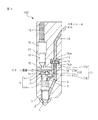
図1は本発明の一実施形態の燃料噴射弁100の略示断面側面図であり、燃料噴射弁100が、燃料が噴射されないモードである不噴射モードにある場合を示している。図1において、1は燃料を噴射するための燃料噴射孔、2は燃料噴射孔1を開閉するためのニードル弁である。3はニードル弁2を開弁側(図1の上側)に付勢するためのノズル室である。4aはニードル弁2を閉弁側(図1の下側)に付勢するための第一部分制御室、4bはその第一部分制御室4aと連通されている第二部分制御室であって、これら第一部分制御室4aと第二部分制御室4bとで制御室4が構成される。本実施形態の燃料噴射弁100において、上記第一部分制御室4aと上記第二部分制御室4bとは、図1に示されているように第一連通路6及び第二連通路7とによって連通されている。この第一連通路6の第一部分制御室4a側の端部には第一部分制御室4aに流入する燃料量を設定するためのインレットオリフィス8が設けられており、第二連通路7の第二部分制御室4b側の端部には第一部分制御室4aから流出する燃料量を設定するためのアウトレットオリフィス9が設けられている。
Hereinafter, embodiments of the present invention will be described with reference to the accompanying drawings.
FIG. 1 is a schematic cross-sectional side view of a
10は、燃料排出通路を構成する低圧室であり、燃料油を回収するリターン通路へ連通している。上記制御室4(より詳細には、第二部分制御室4b)と低圧室10との間の接続部には制御弁11が設けられており、この制御弁11を開閉することで制御室4と低圧室10との間の連通を断続することができる。
12は、コモンレール(蓄圧室)から燃料噴射弁100へと供給される高圧燃料を燃料噴射孔1へと導くための燃料噴射弁100内に設けられた燃料通路であり、この燃料通路12は分岐して上記第一連通路6と上記ノズル室3へと接続されている。また、燃料通路12には、オリフィスプレート室13が設けられ、その中にはオリフィスプレート14が配設されている。オリフィスプレート14には、同オリフィスプレート14の下流側直近の燃料通路12の断面積よりも小さい断面積を有する貫通孔14aが一つ設けられている。なおここで、上記オリフィスプレート室13及び上記オリフィスプレート14は、上記オリフィスプレート14の位置が上記オリフィスプレート室13内において、ほぼ総ての燃料が上記貫通孔14aを通って流れる閉位置と、燃料が上記オリフィスプレート14の外周縁部を越えて流れることが可能な開位置との間で移動され得るような形状及び大きさに構成されている。詳細については後述するが、このような構成を有することで、本実施形態の燃料噴射弁100においては上記オリフィスプレート14の位置を閉位置と開位置とで切替えることによって燃料通路12内にオリフィス(流路断面縮小部)が存在する状態と存在しない状態とを切替えることができるようになっている。なお、本実施形態の燃料噴射弁100においては、上記オリフィスプレート14には、貫通孔14aが一つだけ設けられていたが、他の実施形態ではオリフィスプレートに複数の貫通孔が設けられていてもよい。
更に、図1において、15はピエゾ式アクチュエータ、16は大径ピストン、17は変位伝達室、18は小径ピストンである。そして、小径ピストン18の下方端部は上記低圧室10内に配設された分配ロッド部材19に係合しており、この分配ロッド部材19は更に上記制御弁11と上記オリフィスプレート14の位置を変更するためのバランスロッド部材20とに係合している。すなわち、本実施形態の燃料噴射弁100では、ピエゾ式アクチュエータ15を作動せしめると、その動作が大径ピストン16、変位伝達室17、小径ピストン18、分配ロッド部材19と伝達され、制御弁11を作動させることができると共に、バランスロッド部材20を介して上記オリフィスプレート14の位置を変更することもできる。
Further, in FIG. 1, 15 is a piezoelectric actuator, 16 is a large-diameter piston, 17 is a displacement transmission chamber, and 18 is a small-diameter piston. The lower end of the small-
また、本実施形態の燃料噴射弁100において、上記バランスロッド部材20は、第一短寸バランスロッド20aと第二短寸バランスロッド20bとから構成されており、それぞれが対応するバランスロッドシリンダ21a、21b内を長手方向に移動できるようにされている。そして、本実施形態の燃料噴射弁100においては、上記第一短寸バランスロッド20aと上記第二短寸バランスロッド20bとは、ほぼ等しい横断面積を有するように構成されている。また、本実施形態の燃料噴射弁100では、第一短寸バランスロッド20aと第二短寸バランスロッド20bとの間に分配ロッド部材19が介在するように構成されていて、第一短寸バランスロッド20aの分配ロッド部材19とは反対側の端面が上記オリフィスプレート室13に面し、その一部はオリフィスプレート14に覆われるようにされていると共に、第二短寸バランスロッド20bの分配ロッド部材19とは反対側の端面が上記燃料通路12に面するようにされている。つまり本実施形態の燃料噴射弁100においては、バランスロッド部材20の両端面に、直接もしくはオリフィスプレート14を介して上記燃料通路12内の燃料の圧力が作用するようにされている。
Further, in the
なお、上述したように本実施形態の燃料噴射弁100においてはピエゾ式アクチュエータ15が用いられているが、他の実施形態では、他の任意のアクチュエータを使用可能である。
As described above, the
ところで、図1に示された不噴射モードにおいては、ピエゾ式アクチュエータ(以下、単に「アクチュエータ」という)15の動作量がゼロとされる。このようにすると、制御弁11が閉じられて、制御室4(より詳細には第二部分制御室4b)と低圧室10との間の連通が遮断されるので、制御室4内の燃料が低圧室10を介してリターン通路に流出できなくなり、制御室4内の圧力が上昇する。その結果、ニードル弁2が閉弁側(図1の下側)に付勢され、燃料噴射孔1は閉じられる。
By the way, in the non-injection mode shown in FIG. 1, the operation amount of the piezo actuator (hereinafter simply referred to as “actuator”) 15 is set to zero. As a result, the
また、アクチュエータ15の動作量がゼロとされている場合には、バランスロッド部材20は図1に示された定位置に維持され、オリフィスプレート14の位置は閉位置とされる。したがって、この場合には、燃料通路12内にオリフィス(流路断面縮小部)が存在する状態になっている。
When the operation amount of the
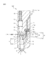
次に図2について説明する。図2は、本実施形態の燃料噴射弁100が、燃料噴射率が比較的低くされる低噴射率噴射モードにされた場合を示す図1と同様の図である。図2に示すように、この低噴射率噴射モードを実現する場合には、アクチュエータ15が作動せしめられ、その時のアクチュエータ動作量が、制御弁11を開き、制御室4(より詳細には第二部分制御室4b)と低圧室10とを連通させる一方で、バランスロッド部材20は定位置に維持し、オリフィスプレート14の位置が閉位置のままとされるような動作量とされる。なお、本実施形態の燃料噴射弁100では、このように制御弁11が開かれると、図2に示されているように、制御室4と低圧室10とが連通される一方で、第一連通路6の第二部分制御室4b側端部開口が閉止されるようになっている。
Next, FIG. 2 will be described. FIG. 2 is a view similar to FIG. 1 showing a case where the
上記のようにアクチュエータ15が作動せしめられると、制御弁11が開かれ、制御室4と低圧室10とが連通されるので、制御室4内の燃料が低圧室10を介してリターン通路に流出できるようになり、制御室4内の圧力が低下する。その結果、ニードル弁2がノズル室3内の燃料の圧力によって開弁側(図1の上側)に移動され、燃料噴射孔1が開かれる。
When the
一方、この時オリフィスプレート14の位置は閉位置のままとされているので、燃料通路12を流れる燃料のほぼ総てがオリフィスプレート14の貫通孔14aを通って流れることになる。そのため、燃料通路12内の燃料の圧力は、オリフィスプレート14の下流側でその上流側よりも低くなり、その結果としてノズル室3における燃料の圧力も低くなって燃料噴射率の低い噴射が行われるようになる。
On the other hand, since the position of the
また、この低噴射率噴射モードにおいては、上述したようにオリフィスプレート14が閉位置にある状態で噴射が行われるので、先に述べた燃料の通路にオリフィス(流路断面縮小部)を設けることによる圧力波の減衰効果を得ることができる。
Further, in this low injection rate injection mode, since the injection is performed with the
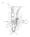
次に図3について説明する。図3は、本実施形態の燃料噴射弁100が、燃料噴射率が比較的高くされる高噴射率噴射モードにされた場合を示す図1と同様の図である。図3に示すように、この高噴射率噴射モードを実現する場合には、アクチュエータ15が作動され、その時のアクチュエータ動作量が、制御弁11を開き、制御室4(より詳細には第二部分制御室4b)と低圧室10とを連通させると共に、バランスロッド部材20を図3において上側に移動させてオリフィスプレート14を持ち上げ、オリフィスプレート14の位置を開位置とするような動作量とされる。
Next, FIG. 3 will be described. FIG. 3 is a view similar to FIG. 1 showing a case where the
そして本実施形態の燃料噴射弁100では、この高噴射率噴射モードを実現する場合のアクチュエータ動作量は、上述の低噴射率噴射モードを実現する場合のアクチュエータ動作量よりも大きい。すなわち、本実施形態の燃料噴射弁100においては、上記分配ロッド部材19が、上記アクチュエータ動作量が予め定めた動作量以下の時には上記制御弁11を開くのみであり、上記予め定めた動作量よりも大きい時には上記制御弁11を開くと共に上記バランスロッド部材20を移動させ上記オリフィスプレート14の位置を開位置とするように構成されている。なお、図3に示されているように、この高噴射率噴射モードを実現する場合においても、上述の低噴射率噴射モードを実現する場合と同様に、第一連通路6の第二部分制御室4b側端部開口が閉止される。
In the
そして、上記のような動作量(すなわち、上記予め定めた動作量より大きい動作量)でアクチュエータ15が作動せしめられると、上述の低噴射率噴射モードを実現する場合と同様に、制御弁11が開かれて制御室4と低圧室10とが連通されるので、制御室4内の燃料が低圧室10を介してリターン通路に流出できるようになり、制御室4内の圧力が低下する。その結果、ニードル弁2がノズル室3内の燃料の圧力によって開弁側(図1の上側)に移動され、燃料噴射孔1が開かれる。
When the
一方、この時オリフィスプレート14は開位置とされているので、燃料通路12を流れる燃料は上記オリフィスプレート14の外周縁部を越えて流れることも可能である。そのため、燃料通路12内にオリフィス(流路断面縮小部)が存在しない状態となり、燃料通路12内の燃料の圧力は、オリフィスプレート14の下流側でもその上流側と同様に高くなる。そしてその結果としてノズル室3における燃料の圧力も高くなって燃料噴射率の高い噴射が行われるようになる。
On the other hand, since the
以上のように、本実施形態の燃料噴射弁100では、当該燃料噴射弁100内の燃料通路12に配設されたオリフィスプレート14の位置が上記閉位置と上記開位置とで切替えられるようになっている。そして、このような構成とすることにより、上記オリフィスプレート14の位置を上記閉位置とした時には燃料噴射に伴う圧力波を減衰させることができると共に、上記オリフィスプレート14の位置を切替えることによって燃料噴射率の制御、すなわち切替えも行うことができる。特に本実施形態の燃料噴射弁100では、上記オリフィスプレート14が燃料噴射弁100内の燃料通路12に配設されており、燃料噴射率の制御のために圧力を変化させる必要がある燃料量(すなわち、オリフィスプレート14より下流側にある燃料量)が少ないので燃料噴射率を高い応答性で制御することができる。
As described above, in the
また、本実施形態の燃料噴射弁100では、上記オリフィスプレート14が閉位置にある時に、上記オリフィスプレート14の下流側の面がシール面14bを構成するようになっている。上記オリフィスプレート14が閉位置にある時に、燃料の噴射等によって上記燃料通路12内の燃料が流れ始めると上記オリフィスプレート14の上流側が高圧、下流側が低圧となるので、上記オリフィスプレート14は下流側に押圧されることになる。したがって、上記のような構成とすることによって、燃料の噴射等により上記燃料通路12内の燃料が流れている時に、上記オリフィスプレート14の位置が保持され、シール面14bにおいて安定的なシールが提供されるようになる。
Further, in the
更に、上述したように本実施形態の燃料噴射弁100では、上記オリフィスプレート14の位置の切替えは、上記オリフィスプレート14と係合するバランスロッド部材20を長手方向に移動することによって行われ、同バランスロッド部材20の長手方向の両端面には、上記燃料通路12内の燃料の圧力が作用するように構成されている。
Further, as described above, in the
そして、このような構成とすることで、上記バランスロッド部材20に作用する上記燃料通路12内の燃料からの力をバランスさせることができるので上記バランスロッド部材20の長手方向の移動をより小さな力で行うことができ、その結果として、より小さな力で上記燃料通路12内にある上記オリフィスプレート14の位置の切替えを行うことができる。なお、このようにより小さな力で上記バランスロッド部材20の移動ができ上記オリフィスプレート14の位置の切替えができる構成とすることで、上記アクチュエータ15の小型化を図ることができる。
And by setting it as such a structure, since the force from the fuel in the said fuel channel |
また、本実施形態の燃料噴射弁100において上記バランスロッド部材20は、先にも述べたように上記燃料通路12内の燃料の圧力が作用する両端面のうちの一端面側の第一短寸バランスロッド20aと他端面側の第二短寸バランスロッド20bとで構成されていて、それぞれが対応するバランスロッドシリンダ21a、21b内を長手方向に移動できるようになっている。
Further, in the
そして、本実施形態の燃料噴射弁100は、このような構成を有することで、より容易にバランスロッド部材20とバランスロッドシリンダ21との間のクリアランスの最小化が図れるようになっている。すなわち、バランスロッド部材20とバランスロッドシリンダ21との間のクリアランスはそこからの燃料漏れを最小限に留めるためにできるだけ小さくすることが望ましい。一方、本実施形態の燃料噴射弁100のように、バランスロッドシリンダ21がバランスロッド部材20の両端部について別々に構成されている場合には、バランスロッド部材20が長寸の一体部材で構成されていると、上記クリアランスの大きさに両バランスロッドシリンダ21a、21bについての同軸度が大きく影響する。このため、上記クリアランスを小さくするためには、両バランスロッドシリンダ21a、21bについての高い同軸度が要求されることになる。
The
これに対し、本実施形態の燃料噴射弁100のようにバランスロッド部材20が第一短寸バランスロッド20aと第二短寸バランスロッド20bとで構成されている場合には、上記クリアランスの大きさに対する二つのバランスロッドシリンダ21a、21bの同軸度の影響を排除することができる。つまりこの場合には、各短寸バランスロッド20a、20bとそれに対応するバランスロッドシリンダ21a、21bとの組合せで、それぞれにクリアランスの最小化を図ればよい。この結果、より容易に上記クリアランスの最小化を図ることが可能となる。
On the other hand, when the
また、本実施形態の燃料噴射弁100においては、上述したように分配ロッド部材19が設けられており、その働きにより、一つのアクチュエータ15によって上記制御弁11の作動と上記バランスロッド部材20を介した上記オリフィスプレート14の位置の切替えとの両方が行えるようになっている。換言すれば、本実施形態の燃料噴射弁100においては、上記制御弁11を開閉するアクチュエータ15によって上記バランスロッド部材20を移動することができ、したがって、上記オリフィスプレート14の位置の切替えを行うことができる。そして、このような構成では、上記オリフィスプレート14の位置の切替えを行うための専用のアクチュエータを設ける必要がないので、製造コストの低減を図ることができる。
Further, in the
更に、本実施形態の燃料噴射弁100では、上述したように、上記分配ロッド部材19が、上記アクチュエータ15の動作量が予め定めた動作量以下の時には上記制御弁11を開くのみであり、上記予め定めた動作量よりも大きい時には上記制御弁11を開くと共に上記バランスロッド部材20を移動させ上記オリフィスプレート14の位置を開位置とするように構成されている。
Furthermore, in the
これにより、例えば、上記アクチュエータ15の動作量が予め定めた動作量以下の時には、上記制御弁11は開かれるが上記バランスロッド部材20は移動されない。そしてこの場合には、上記オリフィスプレート14の位置が閉位置にある状態で上記燃料噴射孔1が開かれることになるので、上記オリフィスプレート14下流の燃料の圧力は低下し、低噴射率の燃料噴射が行われることになる。
Thereby, for example, when the operation amount of the
一方、上記アクチュエータ15の動作量が上記予め定めた動作量よりも大きい時には、上記制御弁11が開かれると共に上記バランスロッド部材20が移動され上記オリフィスプレート14の位置が開位置とされる。この場合には、上記オリフィスプレート14の位置が開位置にある状態で上記燃料噴射孔1が開かれることになるので、上記オリフィスプレート14によってその下流の燃料の圧力が大きく低下することがなく、高噴射率の燃料噴射が行われることになる。
つまり、本実施形態の燃料噴射弁100では上記アクチュエータ15の動作量を制御することで容易に噴射率を制御する(すなわち切替える)ことができる。
On the other hand, when the operation amount of the
That is, in the
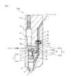
次に本発明の別の実施形態について説明する。図4はこの実施形態の燃料噴射弁200の略示断面側面図であり、燃料噴射弁200が、燃料が噴射されないモードである不噴射モードにある場合を示している。なお、図4において、図1から図3に示した参照番号と同一の参照番号は図1から図3に示した部品又は部分と同一の部品又は部分を示している。
Next, another embodiment of the present invention will be described. FIG. 4 is a schematic cross-sectional side view of the
本実施形態の燃料噴射弁200と上述した燃料噴射弁100とは、その構成及び作動、並びに作用効果について共通する部分を多く有しており、これら共通する部分については原則として説明を省略する。燃料噴射弁200の構成と燃料噴射弁100の構成とを比較すると、本実施形態の燃料噴射弁200では、オリフィスプレート室13に付勢手段であるスプリング32が配設されており、オリフィスプレート14を介して、バランスロッド部材30に対して、上記オリフィスプレート14の位置を閉位置とする方向に上記バランスロッド部材30を移動させる向きに所定の大きさの力を作用させるようになっている。
The
また、本実施形態の燃料噴射弁200は分配ロッド部材19を有しておらず、したがってアクチュエータ15は制御弁11のみを直接的に作動せしめるようになっている。更に、本実施形態の燃料噴射弁200では、第一短寸バランスロッド30aと第二短寸バランスロッド30bとが異なる太さ(直径)で構成され、それに応じて二つのバランスロッドシリンダ31a、31bも異なるシリンダ径で構成されている。より詳細には、第二短寸バランスロッド30bの横断面積の方が第一短寸バランスロッド30aの横断面積よりも大きくされている。そして、この結果として、本実施形態の燃料噴射弁200においては、上記オリフィスプレート14の位置を開位置とする方向に上記バランスロッド部材30を移動させる向きに燃料の圧力を受ける上記バランスロッド部材の端面の面積(すなわち、第二短寸バランスロッド30bの端面の面積)が、もう一方の端面の面積(すなわち、第一短寸バランスロッド30aの端面の面積)よりも大きくなっている。
In addition, the
そして、上記のような構成を有することにより、本実施形態の燃料噴射弁200においては、燃料通路12内の燃料の圧力に応じて自動的に低噴射率の燃料噴射と高噴射率の燃料噴射とを切替えることができる。
And by having the above structures, in the
すなわち、上記燃料通路12内の燃料の圧力が比較的低い時には、上記バランスロッド部材30の両端面が燃料から受ける力の差(=(第二短寸バランスロッド30bの端面の面積−第一短寸バランスロッド30aの端面の面積)×燃料圧力)が上記スプリング32により作用せしめられる所定の大きさの力よりも小さいために、上記バランスロッド部材30が移動せず、上記オリフィスプレート14の位置が閉位置に保たれる。したがって、この状態でアクチュエータ15の作動により制御弁11が開弁され、燃料噴射孔1が開かれた場合には、低噴射率の燃料噴射が行われることになる。
That is, when the pressure of the fuel in the
一方、上記燃料通路12内の燃料の圧力が上昇し、上記バランスロッド部材30の両端面が燃料から受ける力の差(=(第二短寸バランスロッド30bの端面の面積−第一短寸バランスロッド30aの端面の面積)×燃料圧力)が上記スプリング32による所定の大きさの力よりも大きくなると、上記バランスロッド部材30が移動し上記オリフィスプレート14の位置が自動的に開位置になる。そして、この状態でアクチュエータ15の作動により制御弁11が開弁され、燃料噴射孔1が開かれた場合には、高噴射率の燃料噴射が行われることになるのである。
On the other hand, the pressure of the fuel in the
本実施形態の燃料噴射弁200によれば、このように上記燃料通路12内の燃料の圧力に応じて自動的に低噴射率の燃料噴射と高噴射率の燃料噴射とを切替えることができる。また、この切替えの行われる燃料の圧力は、付勢手段であるスプリング32により上記バランスロッド部材30に対して作用せしめられる力の大きさ等を調節することにより所望の値に設定可能である。
According to the
次に本発明の更に別の実施形態について説明する。図5はこの実施形態の燃料噴射弁300の略示断面側面図であり、燃料噴射弁300が、燃料が噴射されないモードである不噴射モードにある場合を示している。なお、図5において、図1から図4に示した参照番号と同一の参照番号は図1から図4に示した部品又は部分と同一の部品又は部分を示している。
Next, still another embodiment of the present invention will be described. FIG. 5 is a schematic sectional side view of the
本実施形態の燃料噴射弁300と上述した燃料噴射弁100及び200とは、その構成及び作動、並びに作用効果について共通する部分を多く有しており、これら共通する部分については原則として説明を省略する。実際、本実施形態の燃料噴射弁300の構成は燃料噴射弁100の構成と燃料噴射弁200の構成とを合わせたような構成となっている。すなわち、本実施形態の燃料噴射弁300は、燃料噴射弁100と同様に分配ロッド部材19を有し、また、燃料噴射弁200と同様にオリフィスプレート室13に配設されたスプリング32を有している。
The
更に、本実施形態の燃料噴射弁300のバランスロッド部材40は、燃料噴射弁200の場合と同様に、第一短寸バランスロッド40aと第二短寸バランスロッド40bとが異なる太さで構成され、それに応じて二つのバランスロッドシリンダ41a、41bが異なるシリンダ径で構成されている。すなわち、本実施形態の燃料噴射弁300においても第二短寸バランスロッド40bの横断面積の方が第一短寸バランスロッド40aの横断面積よりも大きくされており、これによって、上記オリフィスプレート14の位置を開位置とする方向に上記バランスロッド部材40を移動させる向きに燃料の圧力を受ける上記バランスロッド部材の端面の面積(すなわち、第二短寸バランスロッド40bの端面の面積)が、もう一方の端面の面積(すなわち、第一短寸バランスロッド40aの端面の面積)よりも大きくなっている。
Furthermore, the
そして、以上のような構成を有する本実施形態の燃料噴射弁300においては、アクチュエータ15の作動時の駆動力の大きさと燃料通路12内の燃料の圧力とに応じて低噴射率の燃料噴射と高噴射率の燃料噴射とが切替えられる。
In the
すなわち、燃料噴射を行うべくアクチュエータ15を作動させる時の駆動力の大きさとその時に上記バランスロッド部材40の両端面が燃料から受ける力の差(=(第二短寸バランスロッド40bの端面の面積−第一短寸バランスロッド40aの端面の面積)×燃料圧力)との合計が上記スプリング32により作用せしめられる所定の大きさの力よりも小さい場合には、上記バランスロッド部材40が移動しないので上記オリフィスプレート14の位置が閉位置に保たれたたま燃料噴射が行われ、この場合には低噴射率の燃料噴射が行われることになる。
That is, the difference between the magnitude of the driving force when the
一方、燃料噴射を行うべくアクチュエータ15を作動させる時の駆動力の大きさとその時に上記バランスロッド部材40の両端面が燃料から受ける力の差(=(第二短寸バランスロッド40bの端面の面積−第一短寸バランスロッド40aの端面の面積)×燃料圧力)との合計が上記スプリング32による所定の大きさの力よりも大きい場合には、上記バランスロッド部材40が移動し上記オリフィスプレート14の位置が開位置にされるので、この場合には高噴射率の燃料噴射が行われることになる。
On the other hand, the difference between the magnitude of the driving force when the
そして、本実施形態の燃料噴射弁300では、上述したようにアクチュエータ15の作動時の駆動力の大きさと燃料通路12内の燃料の圧力とに応じて低噴射率の燃料噴射と高噴射率の燃料噴射との切替えが行われるので、例えば、上記ピエゾ式アクチュエータ15の作動時の駆動力の大きさを変更することによって上記の切替えの行われる燃料の圧力を変更することができる。また、例えばアクチュエータ制御の単純化のために上記アクチュエータ15の作動時の駆動力は一定にしておき、その一定の駆動力に対応する所定の燃料圧力で低噴射率の燃料噴射と高噴射率の燃料噴射との切替えが自動的に行われるようにすることもできる。
In the
あるいは、上記アクチュエータ15の作動時の駆動力として大小二つの駆動力を設定し、上記アクチュエータ15が比較的小さい第一の駆動力を以って作動せしめられた時には、上記オリフィスプレート14の位置が閉位置にあり、上記アクチュエータ15が上記第一の駆動力よりも大きい第二の駆動力を以って作動せしめられた時には、上記オリフィスプレート14の位置が開位置となるようにしてもよい。
Alternatively, when the
すなわち、この場合には例えば、上記第一及び第二の駆動力が上記スプリング32により作用せしめられる力の大きさを考慮して決定され、燃料通路12内の燃料の圧力が燃料噴射の噴射率の切替えを行うべき所定圧力未満の時には、上記アクチュエータ15を第一の駆動力を以って作動せしめ、上記燃料の圧力が燃料噴射の噴射率の切替えを行うべき所定圧力以上の時には、上記アクチュエータ15を第二の駆動力を以って作動せしめるようにする。
That is, in this case, for example, the first and second driving forces are determined in consideration of the magnitude of the force exerted by the
そしてこのようにすると、上記燃料通路12内の燃料の圧力により作用する力のバランスに加え、上記アクチュエータ15の駆動力を変化させることによっても上記オリフィスプレート14の位置の切替えが制御されるので、上記の低噴射率の燃料噴射と高噴射率の燃料噴射との切替えを確実に所望のタイミングで行わせることができる。
And in this way, the position of the
すなわち例えば、上記切替えが上記燃料通路12内の燃料の圧力に応じて自動的に行われるようになっている場合には、上記燃料の圧力が上記切替えが行なわれるべき圧力に近づいた時に、機器の個体差等によって上記切替えの起こるタイミングが異なる恐れがある。これに対し、本実施形態の燃料噴射弁300において、上述したように上記燃料の圧力が上記切替えを行うべき所定圧力以上となった場合には上記アクチュエータ15を上記第二の駆動力(大きい駆動力)を以って作動せしめるようにしておけば、確実に上記切替えを行わせることができる。
That is, for example, when the switching is automatically performed in accordance with the fuel pressure in the
次に、以上で説明した燃料噴射弁100、200、300の制御方法について説明する。すなわち、上述の燃料噴射弁100、200、300は、例えば、多段噴射を行う低中負荷運転域では上記オリフィスプレート14の位置が閉位置とされ、高噴射率の要求される高負荷運転域では上記オリフィスプレート14の位置が開位置とされるように制御することができる。
Next, a method for controlling the
一般に多段噴射が行われる場合には、噴射間隔が短く、後噴射が前噴射に伴う圧力波の影響を受け易い。この点、上述のような制御方法をとれば、多段噴射を行う低中負荷運転域では上記オリフィスプレート14の位置が閉位置とされるので、前噴射に伴う圧力波を減衰させることができ、この影響による後噴射の噴射量変動等を抑制することができる。一方、高噴射率の要求される高負荷運転域では上記オリフィスプレート14の位置が開位置とされるので、高噴射率の燃料噴射を実現することができる。すなわち、この制御方法によれば、多段噴射を行う際の圧力波の減衰(その結果としての噴射量変動等の抑制)と、高負荷運転域での高噴射率の燃料噴射の実現とを両立することができる。
In general, when multistage injection is performed, the injection interval is short, and the post-injection is easily affected by the pressure wave accompanying the pre-injection. In this regard, if the control method as described above is taken, the position of the
また、上述の燃料噴射弁100、200、300は、早期パイロット噴射とポスト噴射とのうちの少なくとも一方の噴射を行う時には、上記オリフィスプレート14の位置を閉位置とするように制御されてもよい。
Further, the
早期パイロット噴射(例えば、クランク角が圧縮上死点前30°よりも早期での噴射)やポスト噴射が実施される際には、シリンダ内圧力が低いため、ボアフラッシング(シリンダボアへの燃料付着)が発生し易い。特に、燃料噴射の噴霧貫徹力が大きいとボアフラッシングの発生する可能性が高くなる。ボアフラッシングが発生するとオイルが希釈されてしまうという問題がある。これに対し、上記のような制御方法をとれば、早期パイロット噴射やポスト噴射を行う時には、上記オリフィスプレート14の位置が閉位置とされ、これらの燃料噴射を行う際の噴射圧が低く抑えられる。これにより、噴霧貫徹力が低く抑えられるので、上記のような制御方法をとることによってボアフラッシングの発生を抑制することができる。
When early pilot injection (for example, injection at an earlier crank angle than 30 ° before compression top dead center) or post injection is performed, the cylinder internal pressure is low, so bore flushing (attachment of fuel to the cylinder bore) Is likely to occur. In particular, if the spray penetration force of fuel injection is large, the possibility of occurrence of bore flushing increases. When bore flushing occurs, there is a problem that the oil is diluted. On the other hand, if the control method as described above is taken, the position of the
100、200、300…燃料噴射弁
1…燃料噴射孔
2…ニードル弁
3…ノズル室
4…制御室
10…低圧室
11…制御弁
12…燃料通路
13…オリフィスプレート室
14…オリフィスプレート
15…ピエゾ式アクチュエータ
19…分配ロッド部材
20、30、40…バランスロッド部材
100, 200, 300 ...
Claims (11)
燃料噴射弁内に設けられている上記燃料噴射孔へ通ずる燃料通路内に少なくとも一つの貫通孔を有するオリフィスプレートが配設されていて、該オリフィスプレートの位置が、ほぼ総ての燃料が上記貫通孔を通って流れる閉位置と、燃料が上記オリフィスプレートの外周縁部を越えて流れることが可能な開位置との間で切替えられるように構成されていることを特徴とする、燃料噴射弁。 In a fuel injection valve that injects high-pressure fuel supplied from a pressure accumulating chamber through a fuel injection hole that can be opened and closed,
An orifice plate having at least one through hole is disposed in a fuel passage that leads to the fuel injection hole provided in the fuel injection valve, and the position of the orifice plate is such that almost all of the fuel passes through the orifice plate. A fuel injection valve configured to be switched between a closed position flowing through a hole and an open position allowing fuel to flow beyond the outer peripheral edge of the orifice plate.
上記バランスロッド部材は、上記アクチュエータの動作を上記制御弁と上記バランスロッド部材とに伝えるように構成された分配ロッド部材を介して、上記制御弁を開閉するアクチュエータによって移動可能である、請求項3または4に記載の燃料噴射弁。 In the fuel injection hole, the valve body is pushed by the pressure of the high pressure fuel by introducing the high pressure fuel into the control chamber with the control valve provided between the control chamber and the fuel discharge passage closed. On the other hand, the control valve is opened by an actuator and the high pressure fuel in the control chamber is discharged into the fuel discharge passage so that the pressing force of the valve body is lowered and opened.
The balance rod member is movable by an actuator that opens and closes the control valve via a distribution rod member configured to transmit the operation of the actuator to the control valve and the balance rod member. Or the fuel injection valve of 4.
Priority Applications (1)
| Application Number | Priority Date | Filing Date | Title |
|---|---|---|---|
| JP2004118149A JP2005299544A (en) | 2004-04-13 | 2004-04-13 | Fuel injection valve and control method thereof |
Applications Claiming Priority (1)
| Application Number | Priority Date | Filing Date | Title |
|---|---|---|---|
| JP2004118149A JP2005299544A (en) | 2004-04-13 | 2004-04-13 | Fuel injection valve and control method thereof |
Publications (1)
| Publication Number | Publication Date |
|---|---|
| JP2005299544A true JP2005299544A (en) | 2005-10-27 |
Family
ID=35331392
Family Applications (1)
| Application Number | Title | Priority Date | Filing Date |
|---|---|---|---|
| JP2004118149A Pending JP2005299544A (en) | 2004-04-13 | 2004-04-13 | Fuel injection valve and control method thereof |
Country Status (1)
| Country | Link |
|---|---|
| JP (1) | JP2005299544A (en) |
Cited By (1)
| Publication number | Priority date | Publication date | Assignee | Title |
|---|---|---|---|---|
| EP2610478A3 (en) * | 2011-12-27 | 2014-01-22 | Robert Bosch Gmbh | Fuel injector valve for combustion engines |
-
2004
- 2004-04-13 JP JP2004118149A patent/JP2005299544A/en active Pending
Cited By (1)
| Publication number | Priority date | Publication date | Assignee | Title |
|---|---|---|---|---|
| EP2610478A3 (en) * | 2011-12-27 | 2014-01-22 | Robert Bosch Gmbh | Fuel injector valve for combustion engines |
Similar Documents
| Publication | Publication Date | Title |
|---|---|---|
| CN1114757C (en) | Fuel injection valve | |
| KR100482901B1 (en) | Fuel injection device for internal combustion engines | |
| CN100366889C (en) | Fuel injection valves for internal combustion engines | |
| KR20090034371A (en) | Injectors for Fuel Injection Systems | |
| CN1462337A (en) | Fuel injection valve for internal-combustion engine | |
| CN101910605B (en) | Engine and control valve assembly having reduced variability in operation over time | |
| CN101680413A (en) | Control valve for a fuel injection valve | |
| EP2134954A2 (en) | Fuel injection control device for internal combustion engine and method of controlling fuel injection for internal combustion engine | |
| EP1780401B1 (en) | Fuel injection device | |
| JP2006512533A (en) | Fuel injection valve with two coaxial valve needles | |
| JP3932688B2 (en) | Fuel injection device for internal combustion engine | |
| CN1993545A (en) | Device for the injection of fuel into the combustion chamber of an internal combustion engine | |
| JP2004517254A (en) | Injection valve | |
| JP4273153B2 (en) | Fuel injector having a direct injection type injection valve member comprising a plurality of parts | |
| JP2015503706A (en) | Fuel injector | |
| JP4253659B2 (en) | Valve for controlling connections provided in a high-pressure liquid system, in particular a high-pressure liquid system of a fuel injection device for an internal combustion engine | |
| EP1302656B1 (en) | Fuel injection device | |
| US7568634B2 (en) | Injection nozzle | |
| US20050034709A1 (en) | Fuel injector and assembly | |
| JP2005299544A (en) | Fuel injection valve and control method thereof | |
| KR20020027576A (en) | Pressure-controlled, dual-switching high-pressure injector | |
| JP2005537428A (en) | Hydraulic valve regulator for operating gas exchange valve | |
| KR101101048B1 (en) | Equipment at fuel injection mechanisms | |
| KR20080034893A (en) | Fuel injectors for fuel direct engines | |
| CN116771568A (en) | Fuel injector lift control |