JP2005299433A - Blower unit - Google Patents
Blower unit Download PDFInfo
- Publication number
- JP2005299433A JP2005299433A JP2004113813A JP2004113813A JP2005299433A JP 2005299433 A JP2005299433 A JP 2005299433A JP 2004113813 A JP2004113813 A JP 2004113813A JP 2004113813 A JP2004113813 A JP 2004113813A JP 2005299433 A JP2005299433 A JP 2005299433A
- Authority
- JP
- Japan
- Prior art keywords
- outer box
- motor
- impeller
- vibration isolating
- vibration
- Prior art date
- Legal status (The legal status is an assumption and is not a legal conclusion. Google has not performed a legal analysis and makes no representation as to the accuracy of the status listed.)
- Pending
Links
Images
Landscapes
- Structures Of Non-Positive Displacement Pumps (AREA)
Abstract
Description
本発明は、換気や冷却、排塵等に供する送風ユニットに関するものである。 The present invention relates to a blower unit used for ventilation, cooling, dust removal, and the like.
一般に、モータとファンが一体的に形成された送風ユニットは、冷却用等に広く用いられているが、特に高静圧を要求される用途には遠心ファンが用いられる。このように高静圧を確保しようとする場合には、動作回転数を高めることが有効だが、そのためにモータを高出力で使用する場合しばしば、共振音が課題となる。 In general, a blower unit in which a motor and a fan are integrally formed is widely used for cooling or the like, but a centrifugal fan is used particularly for applications that require high static pressure. In order to secure a high static pressure in this way, it is effective to increase the operating rotational speed. However, when using the motor at a high output, resonance noise is often a problem.
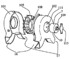
そして従来の送風ユニットは、図4や図5に示すように、吸気口16、排気口17を有し、風路を形成した外箱101、102と、この外箱101、102内に収納され、中央部に空洞部108を有するファン105と、同じく外箱102内に収納されたモータ7から成り、このモータ7の片方の軸受け部109は防振ゴム10を介して、外箱102に設けられ、ファン105の空洞部108に沿うように形成されたフランジ部112に固定され、他方の軸受け部109は防振ゴム10を介して前記外箱102に固定される電動機取付具113に取り付けられることで、ファン105とモータ7系を外箱101、102から振動的に遮断し、共振音を防ぐようにしている(例えば、特許文献1参照)。
しかしながら、前記従来の構成では、ファン105の空洞部108内にクリアランスをおいて、フランジ部112を支持する円筒部111があり、さらにその内部にクリアランスをおいてモータ7があるという構造となり、ファン105あるいは外箱102のサイズに比して、モータ7の直径が小さくなってしまい、高出力のモータ7を収納することができないという課題を有していた。
However, in the conventional configuration, there is a structure in which the
本発明は、前記従来の課題を解決するもので、共振音を防ぎながら、高出力のモータが使用できる送風ユニットを提供することを目的とする。 An object of the present invention is to solve the above-mentioned conventional problems, and to provide a blower unit that can use a high-output motor while preventing resonance noise.
前記従来の課題を解決するために、本発明の送風ユニットは、吸気口と排気口を有し風路を形成した外箱と、シロッコファンの羽根車と、アウターロータ式のモータとを備え、前記モータのロータ部を前記羽根車のハブ部に装着し、前記モータのステータ部を防振部材を介して前記外箱に取り付けたもので、羽根車のハブ部にロータ部が装着されるので、ハブ部の径に対して最大限径の大きいモータを使用することが出来て高出力を実現でき、また、ロータ部、ステータ部間のトルク変動に起因する加振力が防振部材で外箱に伝達せず、振動を防ぐとともに、外箱からの共振音の放射を防ぎ、低騒音化を実現できるものである。 In order to solve the above-described conventional problems, the air blowing unit of the present invention includes an outer box having an air inlet and an air outlet and an air passage, an impeller of a sirocco fan, and an outer rotor type motor, The rotor part of the motor is attached to the hub part of the impeller, and the stator part of the motor is attached to the outer box via a vibration isolating member, and the rotor part is attached to the hub part of the impeller. A motor with a maximum diameter relative to the hub diameter can be used to achieve high output, and the excitation force caused by torque fluctuations between the rotor and stator sections is Not transmitting to the box, preventing vibration and preventing emission of resonance sound from the outer box, thereby realizing low noise.
本発明の送風ユニットは、高出力かつ低騒音、低振動である。 The blower unit of the present invention has high output, low noise, and low vibration.
第1の発明は、吸気口と排気口を有し風路を形成した外箱と、シロッコファンの羽根車と、アウターロータ式のモータとを備え、前記モータのロータ部を前記羽根車のハブ部に装着し、前記モータのステータ部を防振部材を介して前記外箱に取り付けたもので、羽根
車のハブ部にロータ部が装着されるので、ハブ部の径に対して最大限径の大きいモータを使用することが出来て高出力を実現でき、また、ロータ部、ステータ部間のトルク変動に起因する加振力が防振部材で外箱に伝達せず、振動を防ぐとともに、外箱からの共振音の放射を防ぎ、低騒音化を実現できるものである。
A first invention includes an outer box having an intake port and an exhaust port and having an air passage, an impeller of a sirocco fan, and an outer rotor type motor, the rotor portion of the motor being a hub of the impeller The stator part of the motor is attached to the outer box via a vibration isolating member, and the rotor part is attached to the hub part of the impeller, so that the maximum diameter relative to the hub part diameter A large motor can be used to achieve high output, and the excitation force due to torque fluctuation between the rotor and stator parts is not transmitted to the outer box by the vibration isolation member, preventing vibrations, Resonance sound from the outer box can be prevented and noise can be reduced.
第2の発明は、特に、第1の発明のステータ部にフランジを設け、前記フランジの両面を防振部材で挟み、前記防振部材を外箱で押圧して固定したもので、ステータ部と外箱が直接ではなく、必ず防振ゴムを介して接するために、確実に外箱への振動伝達を防ぐとともに、外箱からの共振音の放射を防ぎ、低騒音化を実現できるとともに、外箱で押圧して固定するので、モータを正確に固定することができる。 In particular, the second invention is the one in which the stator part of the first invention is provided with a flange, both surfaces of the flange are sandwiched between vibration isolating members, and the vibration isolating member is pressed and fixed by an outer box. Since the outer box is not in direct contact with the anti-vibration rubber, it is surely prevented from transmitting vibrations to the outer box, and the resonance noise from the outer box is prevented from being radiated. Since the box is pressed and fixed, the motor can be fixed accurately.
第3の発明は、特に、第2の発明のフランジの両面に防振部材をそれぞれ配し、この両防振部材を外箱で軸方向に押圧して固定したもので、モータを容易に、しかも正確に固定することができる。 In particular, the third invention is the one in which the vibration isolating members are respectively arranged on both surfaces of the flange of the second invention, and both the vibration isolating members are fixed by pressing in the axial direction with the outer box. Moreover, it can be accurately fixed.
第4の発明は、特に、第2の発明のフランジの両面に防振部材をそれぞれ配し、この両防振部材をネジと外箱とで軸方向に押圧して固定したもので、モータを容易に、しかも正確に固定することができる。 In particular, the fourth invention is the one in which vibration isolating members are arranged on both surfaces of the flange of the second invention, and both the vibration isolating members are fixed by pressing in the axial direction with screws and an outer box. It can be fixed easily and accurately.
第5の発明は、特に、第1〜4のいずれか1つの発明の外箱の羽根車と対向する面に突出部を設け、前記突出部に、ステータ部、フランジ部、防振部材からなる防振構造の一部または全部を収納したもので、羽根車のハブ部が吸込み経路に大きく突出せず、吸込み領域が阻害されることによる送風性能低下を防止することができる。 5th invention provides a protrusion part in the surface facing the impeller of the outer box of any one of 1st-4th invention especially, and consists of a stator part, a flange part, and a vibration proof member in the said protrusion part. A part or all of the vibration isolating structure is housed, and the hub portion of the impeller does not protrude greatly into the suction path, so that it is possible to prevent the air blowing performance from being deteriorated due to the inhibition of the suction area.
以下、本発明の実施の形態について、図面を参照しながら説明する。なお、この実施の形態によって本発明が限定されるものではない。 Hereinafter, embodiments of the present invention will be described with reference to the drawings. Note that the present invention is not limited to the embodiments.
(実施の形態1)
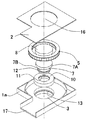
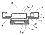
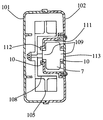
図1は、本発明の第1の実施の形態における送風ユニットの外観を示す分解斜視図で、図2は、同送風ユニットの断面図である。なお、従来例と同一部分については同一符号を付してその説明を省略する。
(Embodiment 1)
FIG. 1 is an exploded perspective view showing an external appearance of a blower unit according to the first embodiment of the present invention, and FIG. 2 is a sectional view of the blower unit. In addition, the same code | symbol is attached | subjected about the part same as a prior art example, and the description is abbreviate | omitted.
図1、2において、下部外箱1aと上部外箱2を組み合わせて、吸気口16、排気口17を有する風路を形成する外箱1を構成し、その内部に、シロッコファンの羽根車5のハブ部8の内側に、アウターロータ式のモータ7のロータ部7Aが密着するように装着される。また、モータ7のステータ部7Bを防振部材である防振ゴム10を介して下部外箱1aに固定する。
1 and 2, the lower
下部外箱1aには羽根車5と反対側の面、即ち羽根車5と対向する面に突出部3を設け、その内部にステータ部7B、フランジ部12、防振ゴム10からなる防振構造の一部を収納する。
The lower
ここで、フランジ部12は、ステータ部7Bに連なりラジアル方向に延出したもので、このフランジ部12に対応する位置に設けた防振ゴム10の溝11にはめ込んで固定する。
Here, the
また、下部外箱1aの突出部3内面にはツメ13を設け、このツメ13と下部外箱1aの突出部3の底面で、フランジ部12を挟んで羽根車5側と、その反対側にある防振ゴム10を軸方向に押圧して固定する。
Further, a
以上のように構成された送風ユニットについて、以下その動作、作用を説明する。 About the ventilation unit comprised as mentioned above, the operation | movement and an effect | action are demonstrated below.
この種の送風ユニットの騒音の内、本発明が対象とするのは主に、モータ7のトルク脈動に起因する共振音である。この音、振動の伝播経路について考えると、まずモータ7のロータ部7Aとステータ部7Bの間で起きたトルク脈動は、ステータ部7Bを回転方向に加振し、その振動が下部外箱1aに直接伝播し、ステータ部7B−外箱1系と共振を起こすと大きい騒音となって、外箱1から外部に放射されたり、振動が外部に伝わる。
Among the noises of this type of blower unit, the present invention is mainly directed to resonance sounds caused by the torque pulsation of the
しかし、本発明ではステータ部7Bと下部外箱1aの間に防振ゴム10が介在して、振動の伝播を完全に遮断するため、共振音を防止できる。
However, in the present invention, since the
また、羽根車5のハブ部8の内側一杯の外径寸法を有するロータ部7Aが装着できるため、送風性能に悪影響を及ぼさずに、モータサイズを大きく取ることが可能となり、モータ出力を大きくすることが出来て、高静圧あるいは高風量の送風ユニットを実現できる。
Further, since the
(実施の形態2)
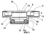
図3は、本発明の第2の実施の形態における送風ユニットの断面図である。なお、上記第1の実施の形態と同一部分については同一符号を付してその説明を省略する。
(Embodiment 2)
FIG. 3 is a cross-sectional view of the blower unit according to the second embodiment of the present invention. Note that the same parts as those in the first embodiment are denoted by the same reference numerals and description thereof is omitted.
本実施の形態は、図3に示すように、フランジ部12は、ステータ部7Bに連なりラジアル方向に延出したもので、このフランジ部12を挟んで羽根車5側とその反対側に防振ゴム10を配設する一方、下部外箱1aの突出部3の底面から立てたボルト14を、フランジ部12と両防振ゴム10に穿った貫通穴10aを通し、ナット15で締めて、防振ゴム10を軸方向に押圧して固定する。
In the present embodiment, as shown in FIG. 3, the
以上のように構成された送風ユニットについて、以下その動作、作用を説明する。 About the ventilation unit comprised as mentioned above, the operation | movement and an effect | action are demonstrated below.
本発明ではステータ部7Bと下部外箱1aの間に防振ゴム10が介在して、振動の伝播を完全に遮断するため、共振音を防止できる。
In the present invention, the
またこの構成では、防振ゴム10の溝11にフランジ部12を押し込んだり、ツメ13のようなアンダーカット部を設けることなく、容易に防振ゴム10を介してモータ7を下部外箱1aに固定できる。
Further, in this configuration, the
以上のように、本発明にかかる送風ユニットは、ハブ部径に対して最大限径の大きいモータを使用することが出来て高出力を実現でき、また、ロータ部、ステータ部間のトルク変動に起因する加振力が防振ゴムによって外箱に伝達されないので、振動を防ぐとともに、外箱からの共振音の放射を防ぎ、低騒音化を実現できるので、小型化、高出力が要求される一般の送風ユニットや、それを用いた機器、装置に広く適用できる。 As described above, the blower unit according to the present invention can use a motor having a maximum diameter with respect to the hub part diameter, can achieve high output, and can also be used for torque fluctuation between the rotor part and the stator part. The resulting excitation force is not transmitted to the outer box by the anti-vibration rubber, which prevents vibration and radiation of the resonance sound from the outer box to achieve low noise, which requires downsizing and high output. The present invention can be widely applied to general blower units and devices and apparatuses using the same.
1 外箱
1a 下部外箱
2 上部外箱
3 突出部
5 羽根車
7 モータ
7A ロータ部
7B ステータ部
8 ハブ部
10 防振ゴム(防振部材)
11 溝
12 フランジ部
13 ツメ
14 ボルト
16 吸気口
17 排気口
DESCRIPTION OF
11 Groove 12
Claims (5)
Priority Applications (1)
| Application Number | Priority Date | Filing Date | Title |
|---|---|---|---|
| JP2004113813A JP2005299433A (en) | 2004-04-08 | 2004-04-08 | Blower unit |
Applications Claiming Priority (1)
| Application Number | Priority Date | Filing Date | Title |
|---|---|---|---|
| JP2004113813A JP2005299433A (en) | 2004-04-08 | 2004-04-08 | Blower unit |
Publications (1)
| Publication Number | Publication Date |
|---|---|
| JP2005299433A true JP2005299433A (en) | 2005-10-27 |
Family
ID=35331300
Family Applications (1)
| Application Number | Title | Priority Date | Filing Date |
|---|---|---|---|
| JP2004113813A Pending JP2005299433A (en) | 2004-04-08 | 2004-04-08 | Blower unit |
Country Status (1)
| Country | Link |
|---|---|
| JP (1) | JP2005299433A (en) |
Cited By (3)
| Publication number | Priority date | Publication date | Assignee | Title |
|---|---|---|---|---|
| DE102017128223A1 (en) | 2017-02-08 | 2018-08-09 | Shinano Kenshi Co., Ltd. | blowing device |
| JP2022060198A (en) * | 2017-03-21 | 2022-04-14 | 株式会社村田製作所 | CPAP device |
| CN115252995A (en) * | 2015-10-23 | 2022-11-01 | 费雪派克医疗保健有限公司 | Device for providing airflow to the user |
-
2004
- 2004-04-08 JP JP2004113813A patent/JP2005299433A/en active Pending
Cited By (4)
| Publication number | Priority date | Publication date | Assignee | Title |
|---|---|---|---|---|
| CN115252995A (en) * | 2015-10-23 | 2022-11-01 | 费雪派克医疗保健有限公司 | Device for providing airflow to the user |
| DE102017128223A1 (en) | 2017-02-08 | 2018-08-09 | Shinano Kenshi Co., Ltd. | blowing device |
| JP2022060198A (en) * | 2017-03-21 | 2022-04-14 | 株式会社村田製作所 | CPAP device |
| JP7151861B2 (en) | 2017-03-21 | 2022-10-12 | 株式会社村田製作所 | CPAP device |
Similar Documents
| Publication | Publication Date | Title |
|---|---|---|
| US11088592B2 (en) | Electric compressor | |
| JP6658037B2 (en) | Fan motor | |
| JP5124124B2 (en) | Axial fan motor | |
| JP4758166B2 (en) | Motor and water pump | |
| CN104295511A (en) | Shock-absorbing fan | |
| CN101512876B (en) | Outer rotor type fan-motor | |
| EP0408221B1 (en) | DC motor driven centrifugal fan | |
| CN206503769U (en) | centrifugal fan | |
| JP5968901B2 (en) | Motor mount for ventilation systems with improved insulation | |
| TWI566504B (en) | Outer rotor type motor | |
| JP4456347B2 (en) | Fan motor | |
| JP6960004B2 (en) | Blower | |
| US20060257254A1 (en) | Heat dissipation apparatus and fan frame thereof | |
| JP2005299433A (en) | Blower unit | |
| JP2011072124A (en) | Drive motor | |
| US5052888A (en) | DC motor driven centrifugal fan | |
| JP2003269395A (en) | Axial fan | |
| KR101833146B1 (en) | The motor fixing bracket for reduction vibration) | |
| JP2011151206A (en) | Blower fitting structure and apparatus | |
| JP4791107B2 (en) | Axial fan motors, blowers, OA / IT equipment and home appliances | |
| JP2009091962A (en) | Centrifugal fan | |
| WO2012169036A1 (en) | Blower apparatus and gas laser oscillation apparatus | |
| JP2000120599A (en) | Electric blower and vacuum cleaner equipped with the same | |
| JP2003088039A (en) | Motor retaining structure | |
| JPH04262098A (en) | Fitting device for impeller |