JP2005299312A - Spring unit with damper and opening/closing device - Google Patents
Spring unit with damper and opening/closing device Download PDFInfo
- Publication number
- JP2005299312A JP2005299312A JP2004120069A JP2004120069A JP2005299312A JP 2005299312 A JP2005299312 A JP 2005299312A JP 2004120069 A JP2004120069 A JP 2004120069A JP 2004120069 A JP2004120069 A JP 2004120069A JP 2005299312 A JP2005299312 A JP 2005299312A
- Authority
- JP
- Japan
- Prior art keywords
- opening
- torsion coil
- coil spring
- winding portion
- spring
- Prior art date
- Legal status (The legal status is an assumption and is not a legal conclusion. Google has not performed a legal analysis and makes no representation as to the accuracy of the status listed.)
- Pending
Links
- 239000000463 material Substances 0.000 claims abstract description 54
- 238000004804 winding Methods 0.000 claims description 77
- 238000013016 damping Methods 0.000 abstract 3
- 229910000831 Steel Inorganic materials 0.000 description 2
- 239000011347 resin Substances 0.000 description 2
- 229920005989 resin Polymers 0.000 description 2
- 239000010959 steel Substances 0.000 description 2
- 238000005452 bending Methods 0.000 description 1
- 230000006835 compression Effects 0.000 description 1
- 238000007906 compression Methods 0.000 description 1
- 230000000694 effects Effects 0.000 description 1
- 238000000034 method Methods 0.000 description 1
- 238000000465 moulding Methods 0.000 description 1
Images
Classifications
-
- E—FIXED CONSTRUCTIONS
- E05—LOCKS; KEYS; WINDOW OR DOOR FITTINGS; SAFES
- E05F—DEVICES FOR MOVING WINGS INTO OPEN OR CLOSED POSITION; CHECKS FOR WINGS; WING FITTINGS NOT OTHERWISE PROVIDED FOR, CONCERNED WITH THE FUNCTIONING OF THE WING
- E05F1/00—Closers or openers for wings, not otherwise provided for in this subclass
- E05F1/08—Closers or openers for wings, not otherwise provided for in this subclass spring-actuated, e.g. for horizontally sliding wings
- E05F1/10—Closers or openers for wings, not otherwise provided for in this subclass spring-actuated, e.g. for horizontally sliding wings for swinging wings, e.g. counterbalance
- E05F1/12—Mechanisms in the shape of hinges or pivots, operated by springs
- E05F1/1207—Mechanisms in the shape of hinges or pivots, operated by springs with a coil spring parallel with the pivot axis
- E05F1/1215—Mechanisms in the shape of hinges or pivots, operated by springs with a coil spring parallel with the pivot axis with a canted-coil torsion spring
-
- E—FIXED CONSTRUCTIONS
- E05—LOCKS; KEYS; WINDOW OR DOOR FITTINGS; SAFES
- E05D—HINGES OR SUSPENSION DEVICES FOR DOORS, WINDOWS OR WINGS
- E05D11/00—Additional features or accessories of hinges
- E05D11/08—Friction devices between relatively-movable hinge parts
- E05D11/082—Friction devices between relatively-movable hinge parts with substantially radial friction, e.g. cylindrical friction surfaces
- E05D11/084—Friction devices between relatively-movable hinge parts with substantially radial friction, e.g. cylindrical friction surfaces the friction depending on direction of rotation or opening angle of the hinge
-
- E—FIXED CONSTRUCTIONS
- E05—LOCKS; KEYS; WINDOW OR DOOR FITTINGS; SAFES
- E05D—HINGES OR SUSPENSION DEVICES FOR DOORS, WINDOWS OR WINGS
- E05D7/00—Hinges or pivots of special construction
- E05D7/08—Hinges or pivots of special construction for use in suspensions comprising two spigots placed at opposite edges of the wing, especially at the top and the bottom, e.g. trunnions
- E05D7/081—Hinges or pivots of special construction for use in suspensions comprising two spigots placed at opposite edges of the wing, especially at the top and the bottom, e.g. trunnions the pivot axis of the wing being situated near one edge of the wing, especially at the top and bottom, e.g. trunnions
-
- Y—GENERAL TAGGING OF NEW TECHNOLOGICAL DEVELOPMENTS; GENERAL TAGGING OF CROSS-SECTIONAL TECHNOLOGIES SPANNING OVER SEVERAL SECTIONS OF THE IPC; TECHNICAL SUBJECTS COVERED BY FORMER USPC CROSS-REFERENCE ART COLLECTIONS [XRACs] AND DIGESTS
- Y10—TECHNICAL SUBJECTS COVERED BY FORMER USPC
- Y10T—TECHNICAL SUBJECTS COVERED BY FORMER US CLASSIFICATION
- Y10T292/00—Closure fasteners
- Y10T292/51—Seal bolts
Landscapes
- Engineering & Computer Science (AREA)
- Mechanical Engineering (AREA)
- Closing And Opening Devices For Wings, And Checks For Wings (AREA)
- Springs (AREA)
- Vibration Dampers (AREA)
Abstract
Description
本発明は、ダンパー付スプリングユニット、及び扉や蓋等の開閉体を本体に対し回動切り換える開閉装置に関するものである。 The present invention relates to a spring unit with a damper, and an opening / closing device that switches an opening / closing body such as a door and a lid with respect to a main body.
回動式扉等の開閉装置としては、例えば、扉等の開閉体をスプリングにより開方向へ付勢しておき、閉位置での保持を解放することで前記スプリングの付勢力で開方向へ回動切り換えられるようにすることが多い。また、前記スプリングとしては、トーションコイルスプリングが用いられ、開閉体をスプリングの付勢力により閉位置から開方向へ切り換える場合だと、開閉体の閉位置で最大の付勢力を蓄積するよう処理される。 As an opening / closing device such as a rotary door, for example, an opening / closing body such as a door is urged in an opening direction by a spring and released in a closed position by releasing the holding in a closed position. In many cases, it is possible to switch the movement. In addition, as the spring, a torsion coil spring is used, and when the opening / closing body is switched from the closed position to the opening direction by the biasing force of the spring, the maximum biasing force is accumulated at the closing position of the opening / closing body. .
また、従来でも、開閉体の回動速度をオイルダンパー等により制動して急速な回動、それに伴う違和感を緩和するようにしている。ところで、経費等の制約からオイルダンパー等を追加できない場合には、例えば、開閉体の閉位置の近傍にクッション材を配して、バウンドを抑える方法も採られている。更に、クッション材に代えて、簡単に制動作用を得る方法としては、特許文献1の開示されているように、トーションコイルスプリングの巻回部内に回転軸と共に、該回転軸に設けられた切欠部に摩擦部材を配置する構造もある。これは、開閉体が回動するときに、該開閉体と一体に回動するトーションコイルスプリングの巻端の回転に伴って、巻端と共に巻き込まれる巻回部の内径寸法の変化で、該巻回部が摩擦部材を介して回転軸に圧接し、該圧接力ないしは摩擦力を制動力として利用するものである。
Conventionally, the rotational speed of the opening / closing body is braked by an oil damper or the like so as to alleviate rapid rotation and the uncomfortable feeling associated therewith. By the way, when an oil damper or the like cannot be added due to cost constraints, for example, a cushioning material is arranged near the closed position of the opening and closing body to suppress the bounce. Further, as a method of easily obtaining a braking action instead of the cushion material, as disclosed in
上記特許文献1の開閉装置は、摩擦部材が回転軸の一部に付設された構成であるため、摩擦部材が継続使用により摩耗し易く、該摩耗により制動力が早期に不安定になったり、当初の制動力を長期に維持できない。そこで、本発明の目的は、以上のような問題を解消して、簡易でありながら、継続使用しても安定した制動力を長期に維持でき、しかも所望の制動力を簡単に充足できるようにすることにある。
The opening and closing device of
上記目的を達成するために、請求項1の発明は、ダンパー付スプリングユニットとして捉えたもので、両端部の間に巻回部を形成しているトーションコイルスプリングと、筒長手方向に連続したスリットを形成して断面が略C形状をしていると共に、前記巻回部の内径よりも大きな外径として作られて前記巻回部内に縮径した状態で圧入配置されている円筒ばね材とを備え、前記トーションコイルスプリングの端部の回転移動に伴って前記巻回部が前記円筒ばね材を介して内径を変化するときに生成される摩擦力を部材回動時の制動力として利用することを特徴としている。
なお、以上の構造では、前記巻回部と前記円筒ばね材との間にオイル等の介在物を配置することが可能である(請求項2)。
In order to achieve the above-mentioned object, the invention of
In the above structure, inclusions such as oil can be disposed between the winding portion and the cylindrical spring material (Claim 2).
これに対し、請求項3の発明は、開閉装置として捉えたもので、開閉体を、本体に対し軸等を介して回動可能に取り付けると共に、両端部の間に巻回部を有して、一端部を当該開閉体側に係止しかつ他端部を前記本体側に係止しているトーションコイルスプリングの付勢力により開位置と閉位置との何れか一方向へ回動切り換える開閉装置において、前記トーションコイルスプリングが、筒長手方向に連続したスリットを形成して断面略C形状をなし、かつ前記巻回部の内径よりも大きな外径として作られて前記巻回部内に縮径した状態で圧入配置されている円筒ばね材を有し、前記トーションコイルスプリングの端部の回転移動に伴って前記巻回部が前記円筒ばね材を介して内径を変化するときに生成される摩擦力を開閉体用の制動力として利用することを特徴としている。なお、以上の構造では、前記開閉体を閉位置から開位置の方向へ付勢する場合、前記巻回部の内径がトーションコイルスプリングの初期状態(開閉体等へ組み付ける前の状態を意味する)より前記開閉体の開位置で大きく、かつ、前記開閉体の開位置より閉位置で大きくなるよう設定されることが好ましい(請求項4)。 On the other hand, the invention of claim 3 is taken as an opening / closing device, and the opening / closing body is rotatably attached to the main body via a shaft or the like, and has a winding portion between both ends. In an opening / closing apparatus that switches in one direction between the open position and the closed position by the urging force of a torsion coil spring that has one end locked to the opening / closing body and the other end locked to the main body. The torsion coil spring has a continuous C-shaped slit in the longitudinal direction of the cylinder and has a substantially C-shaped cross-section, and is formed with an outer diameter larger than the inner diameter of the winding portion and reduced in diameter within the winding portion. And a frictional force generated when the winding portion changes its inner diameter through the cylindrical spring material as the end portion of the torsion coil spring rotates. As a braking force for the opening and closing body It is characterized in that use. In the above structure, when the opening / closing body is biased from the closed position to the open position, the inner diameter of the winding portion is the initial state of the torsion coil spring (meaning the state before being assembled to the opening / closing body or the like). It is preferable that the opening / closing body is set to be larger at the open position and larger than the opening position of the opening / closing body at the closed position.
以上の各発明では、まず、トーションコイルスプリングが一端部を介して巻回部を更に巻き込む方向へ回動されると、該巻回部の内径が円筒ばね材を締め付けて強い摩擦力を生成するが、その際、円筒ばね材がスリットの幅を縮小して摩擦力をある緩和吸収するよう作用する。反対に、トーションコイルスプリングが一端部を介して巻回部の巻き込みが解かれる方向へ回動されると、該巻回部の円筒ばね材に対する摩擦力を弱めるが、その際、円筒ばね材がスリットの幅を拡大して摩擦力を適度に保つよう作用する。すなわち、この構造では、巻回部や円筒ばね材が摩耗しても、巻回部と共に円筒ばね材の反発力で微妙なトルク調整を行って、摩耗等に起因した制動力の変動幅を抑えて一定の値に維持できる。 In each of the above inventions, first, when the torsion coil spring is rotated in the direction of further winding the winding part through the one end, the inner diameter of the winding part tightens the cylindrical spring material to generate a strong frictional force. However, at that time, the cylindrical spring material acts to reduce and absorb the frictional force by reducing the width of the slit. On the contrary, when the torsion coil spring is rotated in the direction in which the winding portion is unwound through the one end portion, the frictional force of the winding portion against the cylindrical spring material is weakened. It works to keep the frictional force moderate by expanding the width of the slit. In other words, in this structure, even if the winding part or the cylindrical spring material is worn, fine torque adjustment is performed with the repulsive force of the cylindrical spring material together with the winding part to suppress the fluctuation range of the braking force due to wear or the like. Can be maintained at a constant value.
上記したように、本発明にあっては次のような利点を具備できる。
・請求項1の発明では、トーションコイルスプリングが断面略C形状で巻回部の内径よりも大きな外径として作られて巻回部内に圧入配置されている円筒ばね材を有しているため、巻回部や円筒ばね材の摩耗に起因した制動力の変動を、円筒ばね材の反発力で調整して、変動幅を抑えて動作を安定化できる。
・請求項2の発明では、巻回部と前記円筒ばね材との間にオイル等の介在物を配置しているため、介在物によっても制動力を安定化したり微調整できる。
・請求項3の発明では、開閉装置として、簡易な構成により、開閉体の回動速度を長期安定して制動できることに加え、開閉体の回動方向によって制動力の大きさを変えられるという利点を有している。また、トーションコイルスプリング及び円筒ばね材だけから構成されているため簡略化及びコスト低減が図られる。
・請求項4の発明では、開閉装置として、開閉体を閉位置から開方向へトーションコイルスプリングの付勢力により回動する構成において、請求項3の摩擦力ないしは制動力が開閉体の閉位置から開方向への回動時に強く作用し、開位置から閉方向への回動時に弱く作用するため、最適な回動切り換え作動を実現できる。
As described above, the present invention can have the following advantages.
In the invention of
-In invention of Claim 2, since inclusions, such as oil, are arrange | positioned between the winding part and the said cylindrical spring material, braking force can be stabilized or fine-tuned also by inclusions.
The invention according to claim 3 has an advantage that the opening / closing device can be stably braked for a long period of time with a simple configuration, and the magnitude of the braking force can be changed depending on the rotation direction of the opening / closing member. have. Moreover, since it is comprised only from the torsion coil spring and the cylindrical spring material, simplification and cost reduction are achieved.
In the invention of claim 4, as the opening / closing device, the opening / closing body is rotated from the closed position to the opening direction by the biasing force of the torsion coil spring, and the frictional force or braking force of claim 3 is applied from the closed position of the opening / closing body. Since it acts strongly at the time of turning in the opening direction and acts weakly at the time of turning from the open position to the closing direction, an optimum turning switching operation can be realized.
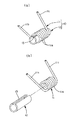
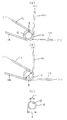
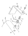
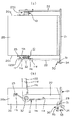
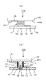
以下、本発明のダンパー付スプリングユニット(以下、スプリングユニットと略称する)及びそれを利用した開閉装置の各形態を図面を参照しながら詳述する。図1はスプリングユニットを示し、同(a)はスプリングユニットの斜視図であり、同(b)は分解図である。図2は各部材の側面図であり、同(a)はスプリングユニットの側面図、同(b)はトーションコイルスプリングの側面図、同(c)は円筒ばね材の側面図である。図3は本発明の開閉装置を適用したボックス構造を示す要部分解図である。図4(a),(b)は前記ボックス構造を上から見た上面図と側面図である。図5(a),(b)は前記ボックス構造の要部上面図とその断面図である。以下の説明では、スプリングユニットを詳述した後、開閉装置に言及する。 Hereinafter, each form of a spring unit with a damper of the present invention (hereinafter abbreviated as a spring unit) and an opening / closing device using the same will be described in detail with reference to the drawings. 1A and 1B show a spring unit, where FIG. 1A is a perspective view of the spring unit, and FIG. 1B is an exploded view. 2A is a side view of the spring unit, FIG. 2B is a side view of the torsion coil spring, and FIG. 2C is a side view of the cylindrical spring material. FIG. 3 is an exploded view of the main part showing a box structure to which the switchgear according to the present invention is applied. 4A and 4B are a top view and a side view of the box structure as seen from above. 5A and 5B are a top view and a cross-sectional view of the main part of the box structure. In the following description, after the spring unit is described in detail, the opening / closing device is referred to.
(スプリングユニット)図1及び図2において、このスプリングユニット10は、線材で作られたトーションコイルスプリング11と、鋼材製又は樹脂製の円筒ばね材12とで構成されている。このうち、トーションコイルスプリング11は、環巻きされている巻回部11aを有し、該巻回部11aの両端部11b,11cがほぼ同じ方向へ延設されている。そして、トーションコイルスプリング11は、図2(b)において、例えば実線で示す位置から、一端部11bを固定した状態で他端部11cを時計回り方向に回動させると、反発力を蓄積しながら巻回部11aが解きほぐされて内径寸法Dが拡がり、又、他端部11cへの回動力を解くと反発力で元の寸法まで戻される。つまり、その戻り動作時には巻回部11aが巻き込まれて内径寸法を縮小する。
(Spring Unit) In FIGS. 1 and 2, the
換言すると、トーションコイルスプリング11は、図2(b)において、他端部11cが一端部11bに対して順に回動されていく位置を、初期位置(イ)、開位置(ロ)、閉位置(ハ)と仮定すると、他端部11cが初期位置(イ)に配置されている時の巻回部11aの内径寸法をD0、他端部11cが開位置(ロ)に配置されている時の巻回部11aの内径寸法をD1、他端部11cが閉位置(ハ)に配置されている時の巻回部11aの内径寸法をD2とすると、各内径寸法はD0<D1<D2の関係となる。
In other words, in FIG. 2B, the
これに対し、円筒ばね材12は、樹脂製の場合は金型成形により、鋼材の場合は例えば弾性板材を円筒状に折り曲げることにより、両端間に隙間(以下、この隙間を「スリット13」という)を設けて、断面が略C形状として作られる。円筒ばね材12の長さは、巻回部11aの軸に沿う方向の長さと同じか、或いは若干大きく形成されている。円筒ばね材12の外径d(巻回部11aに圧入されていないときの外径)は、閉位置(ハ)における巻回部11aの内径寸法D2よりも大きい。すなわち、この例では、d>D2>D1>D0の関係に設定されている。
On the other hand, the
次に、以上の円筒ばね材12をトーションコイルスプリング11に組み付ける操作例を概説する。先ず、トーションコイルスプリング11の一端11bを固定し、巻回部11aを解す方向で、上記した閉位置(ハ)を越えて、巻回部11aの内径Dが円筒ばね材12の外径dよりも大きくなる位置まで回転させる。この状態から、巻回部11a内に円筒ばね材12を差し込む。円筒ばね材12が差し込まれたら、他端11cを回転させていた力を解く。これにより、他端11cが反発力で反対方向、つまり初期位置(イ)方向に回転し、巻回部11aの内径が縮まり、円筒ばね材12の外面に圧接した状態になる。円筒ばね材12は、その圧接力で外径を若干縮径し、閉位置(ハ)では巻回部11aの内径と同じD2、開位置(ロ)では巻回部11aの内径と同じD1、初期位置(イ)では巻回部11aの内径と同じD0の外径になり、常にトーションコイルスプリング11に対して反発力を有した状態で組み込まれる。これにより、トーションコイルスプリング11と円筒ばね材12とはスプリングユニット10として一体化される。そして、以後はこのユニット化された状態で取り扱われる。
Next, an operation example for assembling the above
以上のスプリングユニット10は、図2(a)に示されるように、トーションコイルスプリング11の一端11bを固定し、他端11cを開位置(ロ)に対して、巻回部11aを巻回している方向とは反対側となる閉位置(ハ)まで回転させて、この回転で巻回部11aを巻き解した状態から、該トーションコイルスプリング11の反発力で他端11cを開位置(ロ)方向、すなわち巻回部11aを巻回している方向に向かって回転させると、他端1cの回転に伴って巻回部11aが巻き込まれて内径を狭めながら、該巻回部11aが円筒ばね材12に対して回転する。この構造では、その回転に伴って該巻回部11aの内面が円筒ばね材12の外面に対して更に圧接され、この圧接力が巻回部11aの回転負荷、すなわち、制動力となり、ダンパー効果を生成する。反対に、開位置(ロ)から閉位置(ハ)方向に向かって回転させると、巻回部11aの巻き込みが解され、巻回軸11aと円筒ばね材12との間の摩擦力を弱めながら、他端11cを閉位置(ハ)方向に回転移動させることができる。
As shown in FIG. 2A, the
従って、以上のスプリングユニット10にあっては、円筒ばね材12と巻回部11aとの間には常に反発力による摩擦力が発生していて、トーションコイルスプリング10の一端11bを固定し、他端11cを一方向、すなわち閉位置(ハ)から開位置(ロ)方向に回転させると、巻回部11aが巻き込まれて制動力を高め、反対に開位置(ロ)から閉位置(ハ)方向に向かって回転させると、巻回部11aの巻き込みが解されて制動力を弱める。また、円筒ばね材12は、巻回部11aに対してスリット13を介して縮径され反発力を有した状態で組み込まれているので、巻回部11aや円筒ばね材12が摩耗しても、その反発力で微妙なトルクの調整を行い、長年使用されても初期時とほぼ同じ大きさの制動力を維持できる。
Therefore, in the
ここで、上記した制動力は、例えば、巻回部11aの長さ及び巻径、円筒ばね材12の材質、長さ及び外径並びにスリット13の幅などを適宜に変えることによって設定可能である。また、構造的には、巻回部11aと円筒ばね材12との間に、例えばオイル等の摩擦力調整用部材を介装することもあり、そのような介在物によっても制動力の大きさを変えることができる。
Here, the above-described braking force can be set by appropriately changing, for example, the length and winding diameter of the winding
(開閉装置)図3〜図5は、以上のスプリングユニット10を使用した開閉装置23の一例を示している。この開閉装置23は、機器側の本体20に対し開閉体21が支軸24などを介して回動可能に取り付けられると共に、上述したスプリングユニット10を構成しているトーションコイルスプリング11の付勢力により開位置と閉位置との何れか一方向へ回動切り換えられるようにする。なお、ここでは、開閉体21がトーションコイルスプリング11の付勢力により閉位置から開方向へ自動で回動切り換えられる例で説明する。
(Opening / Closing Device) FIGS. 3 to 5 show an example of the opening /
ここで、本体20の両側面20aは、各側面20aから突設された円柱状の支軸24と、支軸24から少し離れた箇所に設けられたバネ止め部25とを有している。支軸24の外径は、スプリングユニット10の円筒ばね材12がバネ圧縮を損なわれないように、円筒ばね材12の内径dよりも小さく形成され、又、先端には更に小径となった径小軸部26が設けられている。該径小軸部26の先端面にはネジ孔27が形成されている。なお、径小軸部26を除いた支軸24の長さは、スプリングユニット10を構成しているトーションコイルスプリング11の巻回部11aの長さ、又は、円筒ばね材12の長さとほぼ等しく形成されている。これに対し、開閉体21は、本体20の前面を覆う蓋であり、両側の内面に突設されているアーム22,22を有している。各アーム22の先端には軸受孔28が設けられている。符号29は開閉体21に設けられている係合凹所である。この係合凹所29は、本体20側に設けられたラッチ手段30に対応して設けれている。ラッチ手段30は、模式化しているが、軸35を介し枢支され、かつばね部材33により一方向へ付勢されているラッチ部材31と、ラッチ部材31を係合凹所29と係合する係止位置から係止解除位置へ切り換える操作部材34とを有している。
Here, both side surfaces 20 a of the
次に、以上の本体20に対し開閉体21を開閉装置23を介して組み付ける操作例を概説する。なお、スプリングユニット10は、トーションコイルスプリング11として、他端11c側に略L字形状に折り曲げられた掛け止め部11dを設けたものが使用されている。そして、組み付けでは、まず、トーションコイルスプリング11と一体化されている円筒ばね材12を、支軸24に対応させ、支軸24を円筒ばね材12の内部に差し込むようにして、トーションコイルスプリング11の一端11b側をバネ止め部25の下側に係合させる。
Next, an operation example in which the opening /
次いで、巻回部11a内から突出している支軸24の径小軸部26を、アーム22の軸受孔28に挿入して、開閉体21の各アーム22を対応する支軸24に取り付ける。このときには、トーションコイルスプリング11の他端掛け止め部11dがアーム22の下側に係合され、又、この状態でボルト等の止め具32がアーム22側の軸受孔28から径小軸部26のネジ孔27に螺入係止される。これにより、開閉体21の組み付けが完了する。
Next, the small-
以上の開閉装置では、開閉体21が閉位置つまり上記したトーションコイルスプリング11が閉位置(ハ)に配置された状態となるまで時計回り方向に回動されると、ラッチ部材31の爪が係合凹所29と係合し、その閉位置で保持される。開閉体21が閉位置に配置された状態では、トーションコイルスプリング11の巻回部11aは巻き解され、円筒ばね材12と巻回部11aとの間の摩擦力は低くなり、また、トーションコイルスプリング11には開閉体21を常に開位置(ロ)方向に回動しようとする反力が蓄積されている。
In the above opening / closing device, when the opening /
開閉体21が閉位置で保持されている状態で、ラッチ手段30の操作部材34を押し込むと、ラッチ部材31が係合解除方向へ押されて係合凹所29から外れる。これにより、開閉体21は、トーションコイルスプリング11の反力で、径小軸部26を支点にして他端11cが上記した略開位置(ロ)に回転移動されるまで、該他端11cと一体に移動されて開位置に切り換えられる。なお、他端11cが開位置(ロ)方向に向かって回転されると、他端11cの回転に伴ってトーションコイルスプリング11の巻回部11aが巻き込まれながら、該巻回部11aも円筒ばね材12に対して回転する。この構造では、その回転に伴う該巻回部11aの円筒ばね材12に対する摩擦力が制動力となり、例えば、開位置に到達するに従って強くなる制動力を受けることによって回動が緩やかになり、安定した回動が維持されると共に、開閉体21の開位置でのバウンド等も抑えられる。
When the
なお、以上の開閉装置23では、開閉体21が閉から開位置に回動するときに大きな制動力を与える場合について説明したが、勿論、開から閉位置に回動するときに大きな制動力を付与するようにしてもよい。また、開閉装置23は、ボックス構造以外に、回転跳ね上げ式の車両用アシストグリップや各種折り畳み構造などにも適用可能ものである。
In the above opening /
10…スプリングユニット(ダンパ付スプリングユニット)
11…トーションコイルスプリング(11aは巻回部)
12…円筒ばね材
13…スリット
20…本体
21…開閉体
22…アーム
23…開閉装置
24…支軸(26は径小軸部)
10 ... Spring unit (spring unit with damper)
11 ... Torsion coil spring (11a is a winding part)
DESCRIPTION OF
Claims (4)
前記トーションコイルスプリングが、筒長手方向に連続したスリットを形成して断面略C形状をなし、かつ前記巻回部の内径よりも大きな外径として作られて前記巻回部内に縮径した状態で圧入配置されている円筒ばね材を有し、前記トーションコイルスプリングの端部の回転移動に伴って前記巻回部が前記円筒ばね材を介して内径を変化するときに生成される摩擦力を開閉体用の制動力として利用することを特徴とする開閉装置。 The opening / closing body is attached to the main body via a shaft or the like so as to be rotatable, and has a winding portion between both ends, and one end is locked to the opening / closing body and the other end is connected to the main body side. In the opening and closing device that switches in one direction between the open position and the closed position by the urging force of the torsion coil spring that is locked to
In a state where the torsion coil spring forms a slit that is continuous in the longitudinal direction of the cylinder to form a substantially C-shaped cross section and is formed as an outer diameter larger than the inner diameter of the winding portion and is reduced in diameter in the winding portion. It has a cylindrical spring material that is press-fitted, and opens and closes the frictional force that is generated when the winding part changes its inner diameter through the cylindrical spring material as the end of the torsion coil spring rotates. An opening and closing device that is used as a braking force for a body.
When urging the opening / closing body from the closed position to the opening position, the inner diameter of the winding portion is larger at the opening position of the opening / closing body than the initial state of the torsion coil spring, and is closed from the opening position of the opening / closing body. The switchgear according to claim 3, wherein the switchgear increases in position.
Priority Applications (2)
| Application Number | Priority Date | Filing Date | Title |
|---|---|---|---|
| JP2004120069A JP2005299312A (en) | 2004-04-15 | 2004-04-15 | Spring unit with damper and opening/closing device |
| US11/101,474 US20050242594A1 (en) | 2004-04-15 | 2005-04-08 | Spring unit with damper and opening-closing device |
Applications Claiming Priority (1)
| Application Number | Priority Date | Filing Date | Title |
|---|---|---|---|
| JP2004120069A JP2005299312A (en) | 2004-04-15 | 2004-04-15 | Spring unit with damper and opening/closing device |
Publications (1)
| Publication Number | Publication Date |
|---|---|
| JP2005299312A true JP2005299312A (en) | 2005-10-27 |
Family
ID=35186307
Family Applications (1)
| Application Number | Title | Priority Date | Filing Date |
|---|---|---|---|
| JP2004120069A Pending JP2005299312A (en) | 2004-04-15 | 2004-04-15 | Spring unit with damper and opening/closing device |
Country Status (2)
| Country | Link |
|---|---|
| US (1) | US20050242594A1 (en) |
| JP (1) | JP2005299312A (en) |
Cited By (2)
| Publication number | Priority date | Publication date | Assignee | Title |
|---|---|---|---|---|
| KR101029231B1 (en) | 2009-03-18 | 2011-04-18 | 주식회사 득인기공 | Torsion Springs for Foot Brake |
| US20120319422A1 (en) * | 2011-05-19 | 2012-12-20 | Nifco Korea Inc. | Console box |
Families Citing this family (5)
| Publication number | Priority date | Publication date | Assignee | Title |
|---|---|---|---|---|
| US20090032672A1 (en) * | 2007-02-14 | 2009-02-05 | Stephen Vance Cooper | Suspension system for product mounted racing computer |
| CN103670095B (en) * | 2013-12-18 | 2015-12-09 | 湖北工业大学 | A switch door hinge capable of realizing specific angle switch |
| KR102477591B1 (en) * | 2015-02-19 | 2022-12-13 | 사우스코 인코포레이티드 | Method and Pivot Device for Generating Asymmetric Frictional Torque |
| CN107762327B (en) * | 2017-11-20 | 2023-01-13 | 苏州升德精密电气有限公司 | Rotary tripping shutter |
| US11365009B2 (en) | 2018-06-29 | 2022-06-21 | Safran Seats Usa Llc | Spring clutch arm assembly |
Family Cites Families (12)
| Publication number | Priority date | Publication date | Assignee | Title |
|---|---|---|---|---|
| US2862229A (en) * | 1952-02-07 | 1958-12-02 | Charles R Bacca | Spring tensioned radially compressible and longitudinally extensible sectional clamp sleeve |
| CA1326230C (en) * | 1988-03-04 | 1994-01-18 | Yoshiharu Kitamura | Shaft-locking device |
| JP2887680B2 (en) * | 1989-06-14 | 1999-04-26 | 日本発条株式会社 | Hinge device |
| US5191678A (en) * | 1989-10-30 | 1993-03-09 | T.J. Firari Enterprises | Wind resistant door hardware |
| JPH0648178Y2 (en) * | 1989-12-28 | 1994-12-12 | 日本発条株式会社 | Axis locking device |
| JP2852675B2 (en) * | 1989-12-28 | 1999-02-03 | 日本発条株式会社 | Shaft locking device |
| US5467504A (en) * | 1994-02-04 | 1995-11-21 | Chiahuan Spring Co., Ltd. | Hinge for a portable computer |
| US5564163A (en) * | 1994-11-08 | 1996-10-15 | Cema Technologies, Inc. | Lockable hinge assembly |
| US5542505A (en) * | 1995-05-26 | 1996-08-06 | Vadnais Technologies Corporation | Torque limiting device with restraining mechanism |
| US5771539A (en) * | 1996-09-17 | 1998-06-30 | Reell Precision Manufacturing Corporation | Torsion friction spring hinge |
| US7043797B2 (en) * | 1998-04-24 | 2006-05-16 | I.T.W Fastex Italia S.P.A. | Hinge retarding device such as for vehicle glove compartment lids |
| TW534185U (en) * | 2002-09-17 | 2003-05-21 | Hon Hai Prec Ind Co Ltd | Hinge Device |
-
2004
- 2004-04-15 JP JP2004120069A patent/JP2005299312A/en active Pending
-
2005
- 2005-04-08 US US11/101,474 patent/US20050242594A1/en not_active Abandoned
Cited By (3)
| Publication number | Priority date | Publication date | Assignee | Title |
|---|---|---|---|---|
| KR101029231B1 (en) | 2009-03-18 | 2011-04-18 | 주식회사 득인기공 | Torsion Springs for Foot Brake |
| US20120319422A1 (en) * | 2011-05-19 | 2012-12-20 | Nifco Korea Inc. | Console box |
| US8794473B2 (en) * | 2011-05-19 | 2014-08-05 | Nifco Korea Inc. | Console box |
Also Published As
| Publication number | Publication date |
|---|---|
| US20050242594A1 (en) | 2005-11-03 |
Similar Documents
| Publication | Publication Date | Title |
|---|---|---|
| JP6893688B2 (en) | Switchgear switchgear and various switchgear equipped with this switchgear switchgear | |
| JP2009115928A (en) | Document crimping plate opening and closing device and office equipment equipped with document crimping plate | |
| JP5030029B2 (en) | Steering column device | |
| JP2005299312A (en) | Spring unit with damper and opening/closing device | |
| JP6022800B2 (en) | Vehicle handle device | |
| JP4658577B2 (en) | Striker assembly for vehicle | |
| CN112236574A (en) | strut | |
| KR920019662A (en) | Tension Device for Strap Tool | |
| CA2507660C (en) | Pedal assembly | |
| US20140157939A1 (en) | Release mechanism | |
| JP3410386B2 (en) | Retarder device | |
| JP3962817B2 (en) | Tensioner | |
| JP4529059B2 (en) | Rotating damper | |
| JP3490030B2 (en) | Lid opening and closing mechanism for rice cookers, etc. | |
| JP2008272034A (en) | Rotating device and washing machine using the rotating device | |
| KR100803629B1 (en) | Hinge device | |
| JP5666252B2 (en) | Hinge mechanism | |
| JP5067626B2 (en) | Vehicle storage device | |
| JP4829713B2 (en) | Brake device for opening closing member and opening closing member having the same | |
| JPH0235107B2 (en) | JIDOSHAYODOAHANDORUSOCHI | |
| JP3113655U (en) | Door opening adjuster | |
| JP2004360308A (en) | Door checker for vehicles | |
| JP2008304044A (en) | Hinge device | |
| JP2005299876A (en) | Free stop type hinge device | |
| JP4418952B2 (en) | Hinge damper in switchgear |