JP2005299230A - Controller of electric lock and supervising device - Google Patents
Controller of electric lock and supervising device Download PDFInfo
- Publication number
- JP2005299230A JP2005299230A JP2004117171A JP2004117171A JP2005299230A JP 2005299230 A JP2005299230 A JP 2005299230A JP 2004117171 A JP2004117171 A JP 2004117171A JP 2004117171 A JP2004117171 A JP 2004117171A JP 2005299230 A JP2005299230 A JP 2005299230A
- Authority
- JP
- Japan
- Prior art keywords
- electric lock
- controller
- electric
- door
- locks
- Prior art date
- Legal status (The legal status is an assumption and is not a legal conclusion. Google has not performed a legal analysis and makes no representation as to the accuracy of the status listed.)
- Pending
Links
- 238000010276 construction Methods 0.000 abstract description 5
- 230000005540 biological transmission Effects 0.000 description 5
- 238000010586 diagram Methods 0.000 description 4
- 238000009434 installation Methods 0.000 description 4
- 238000000034 method Methods 0.000 description 3
- 230000005284 excitation Effects 0.000 description 2
- 230000007257 malfunction Effects 0.000 description 1
- 238000005192 partition Methods 0.000 description 1
Images

Landscapes
- Lock And Its Accessories (AREA)
Abstract
Description
この発明は、電気錠のコントローラ及び管理装置、特に建物の部屋や通用口に配設された電気錠が配設工事発注された電気錠と同一であるか否かの判別可能なコントローラ及び管理装置に関するものである。 The present invention relates to a controller and a management device for an electric lock, and in particular, a controller and a management device capable of discriminating whether or not an electric lock arranged in a room or a service entrance of a building is the same as an electric lock ordered for installation work. It is about.
従来の建物の部屋や通用口に配設された扉の電気錠は、所定の区画毎に設けられたコントローラに対して電気錠の作動タイプ、例えば通電時施錠型、通電時解錠型、瞬時解錠型等を手入力で登録してデータベースを作成し、場合によってはコントローラによって判別し登録することが行なわれていた。(例えば特許文献1参照)。 The electric locks of the doors installed in the rooms and the entrances of the conventional building are the operation type of the electric lock for the controller provided for each predetermined section, for example, the lock type when energized, the unlock type when energized, the instantaneous A database is created by manually registering the unlocking type or the like, and in some cases, it is determined and registered by a controller. (For example, refer to Patent Document 1).
従来の電気錠のコントローラは以上のように構成され、電気錠コントローラへの電気錠の作動タイプの登録が手入力によって行なわれていたため、電気錠の数が多くなると登録のために多大の工数を要するという問題点があった。
また、手入力による登録ミスも発生して電気錠の動作に不具合が発生するという問題点もあった。更に、当初、各扉に配設すべく工事発注された電気錠の作動タイプと同一の電気錠が各扉に配設されているか否かの照合を行なうことができないという問題点もあった。
The conventional electric lock controller is configured as described above, and the registration of the operation type of the electric lock to the electric lock controller is performed manually. Therefore, if the number of electric locks increases, a large amount of man-hours are required for registration. There was a problem that it took.
In addition, there is a problem that a registration error due to manual input also occurs and a malfunction occurs in the operation of the electric lock. Furthermore, there is also a problem that it is impossible to check whether or not the same electric lock as the operation type of the electric lock ordered for installation at each door is provided at each door.
この発明は、上記のような問題点を解消するためになされたもので、電気錠コントローラに、各扉や通用口に配設された電気錠の作動タイプを判別して自動登録し得る機能に加えて、これらのデータを送信する機能を持たせると共に、各扉への電気錠の配設の際に、どのような作動タイプの電気錠を配設すべきかを指示した工事発注の内容をデータベース化して保有する管理装置を設け、この管理装置から上記電気錠コントローラに対して配設ずみ電気錠の作動タイプのデータの伝送を指示することにより、両データを照合して各扉に配設された電気錠が、当初、配設すべく指示された電気錠の作動タイプと同一であるかどうかを照合確認することができるようにし、また、入退室管理システムの電気錠コントローラとしてカードリーダの接続も可能にした電気錠のコントローラ及び管理装置を提供することを目的とする。 The present invention has been made to solve the above-described problems, and has a function capable of automatically registering an electric lock controller by determining the operation type of the electric lock disposed in each door or service port. In addition, it has a function to transmit these data, and at the time of installation of electric locks on each door, the contents of the work order instructing what type of electric lock should be installed The control device is stored and the control device is instructed to transmit the data of the operation type of the electric lock to the electric lock controller. It is possible to check whether the electric lock is the same as the operation type of the electric lock instructed to be installed at the beginning, and to connect the card reader as an electric lock controller of the entrance / exit management system. And to provide an electric lock controller, and a management apparatus that is also possible.
この発明に係る電気錠のコントローラ及び管理装置は、建物内を複数の区画に区分し、各区画毎に、その区画内の部屋、通用口等に配設された複数の扉にそれぞれ電気錠を配設し、各電気錠の作動タイプを判別して登録するデータベースを有する電気錠コントローラを設けると共に、各区画の電気錠コントローラとデータ伝送可能に接続された管理装置を設け、上記管理装置には各区画のそれぞれの扉に配設すべく工事発注された電気錠の作動タイプのデータベースを有し、上記電気錠コントローラに登録された配設ずみ電気錠の作動タイプと照合し得るようにしたものである。 The controller and the management device for an electric lock according to the present invention divide a building into a plurality of sections, and each of the sections is provided with an electric lock on a plurality of doors provided in a room, a common entrance, etc. in the section. An electric lock controller having a database for determining and registering the operation type of each electric lock is provided, and a management device connected to the electric lock controller of each section so as to be able to transmit data is provided. It has a database of operation types of electric locks ordered to be installed in each door of each section, and can be compared with the operation types of pre-installed electric locks registered in the electric lock controller. It is.
この発明に係る電気錠のコントローラ及び管理装置は以上のように構成されているため、電気錠コントローラが各扉や通用口の電気錠の作動タイプを判別してデータベースに自動的に登録する結果、予めデータベースに各扉の電気錠の作動タイプを手入力により登録する手間が省け、また、手入力による場合の登録ミスも防止することができる。
更に、工事発注されたものと異なる作動タイプの電気錠が扉に配設され、電気錠コントローラに接続されても、管理装置とのデータベースの照合によりミスを発見することができ、警報を発してオペレータに注意を喚起することができる。
Since the controller and the management device of the electric lock according to the present invention are configured as described above, the electric lock controller determines the type of operation of the electric lock of each door or door and automatically registers it in the database. It is possible to save the trouble of manually registering the operation type of the electric lock of each door in the database in advance, and it is possible to prevent registration errors caused by manual input.
Furthermore, even if an electric lock of a different operation type from that ordered is placed on the door and connected to the electric lock controller, a mistake can be found by checking the database with the management device, and an alarm is issued. The operator can be alerted.
実施の形態1.
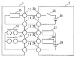
以下、この発明の実施の形態1を図にもとづいて説明する。図1は、実施の形態1における電気錠と、その作動タイプ判別装置の接続関係を示す回路図である。
この図において、電気錠1は端子10、11に接続された電気錠動作コイル15と、端子12、14に接続された解錠状態接点16と、端子13、14に接続された扉状態接点17とを有している。
In this figure, the
また、電気錠の作動タイプ自動判別装置2は端子20、21間に接続された接点用直流電源26及び通電スイッチ25と、端子22、24間に接続されたコイル用直流電源29及び解錠状態コイル27と、端子23及びコイル用直流電源29の間に接続された扉状態コイル28とを有している。
In addition, the automatic lock operation type
次に、この装置による電気錠の動作と作動タイプの自動判別動作について説明する。
先ず、通電スイッチ25を短絡する。この短絡によって電気錠1の電気錠動作コイル15が励磁され、電気錠を施錠または解錠動作させる。
電気錠動作コイル15の励磁によって電気錠を施錠した場合は、解錠状態接点16が開放され、電気錠を解錠した場合は、解錠状態接点16が短絡される。
Next, the operation of the electric lock and the operation type automatic discrimination operation by this apparatus will be described.
First, the
When the electric lock is locked by the excitation of the electric
今、電気錠が通電時施錠型であるとすると、解錠状態接点16は図示のように開放されたままである。従って、解錠状態コイル27が消磁され、電気錠が通電時施錠型であることを判別する。この時、扉は閉じているため扉状態接点17は短絡され、扉状態コイル28が励磁されて扉の閉状態を確認することができる。
Now, assuming that the electric lock is of a locking type when energized, the
また、電気錠が通電時解錠型である場合には、電気錠動作コイル15の励磁によって解錠状態接点16が短絡され、解錠状態コイル27が励磁されることによって通電時解錠型であることが判別される。この時、扉は開放可能な状態であるため扉状態接点17は開放され、扉状態コイル28が消磁されてこの状態を確認することができる。
Further, when the electric lock is of the unlocking type when energized, the unlocking
図2は、通電時施錠型電気錠と通電時解錠型電気錠のそれぞれの判別をするための上述の手順をまとめたものである。
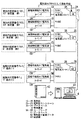
図3は、この発明の実施の形態1の構成を示すブロック図である。
この実施の形態は建物を複数の区画に区分し、例えば図示のように、10階の事務室の扉1及び扉2を区画1及び2とし、それぞれの扉に配設された電気錠1A、1Bに対応する電気錠コントローラとして2Aを配置し、コントローラ内に収納されたデータベース3Aに電気錠1A、1Bのデータを登録するようにしている。
FIG. 2 summarizes the above-described procedure for determining each of the energized lock type electric lock and the energized unlock type electric lock.
FIG. 3 is a block diagram showing the configuration of the first embodiment of the present invention.
In this embodiment, the building is divided into a plurality of sections. For example, as shown in the figure, the
また、9階の事務室の扉1及び扉2を区画3及び4とし、それぞれの扉に配設された電気錠1C、1Dに対応する電気錠コントローラとして2Bを配置し、このコントローラ内に収納されたデータベース3Bに電気錠1C、1Dのデータを登録するようにしている。
以下、同様にして各階毎に電気錠コントローラを配置し、1階の通用口1及び2を区画m-1、mとし、それぞれの扉に配設された電気錠1N、1Mに対応する電気錠コントローラとして2Nを配置し、このコントローラ内に収納されたデータベース3Nに電気錠1N、1Mのデータを登録するようにしている。
Moreover, the
Hereinafter, similarly, an electric lock controller is arranged for each floor, the first-
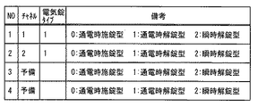
各電気錠コントローラ2A、2B…2Nに登録されるデータは例えば図4に示すようにチャネル番号と電気錠の作動タイプである。なお、電気錠1A、1B…1N、1Mは図1の1に示すように構成され、電気錠コントローラ2A、2B…2Nは図1の2に示すように構成されている。
The data registered in each
また、各区画にはカードリーダ5A、5B…5N、5Mが設けられ、入退室管理システムの電気錠コントローラとしても使用できるようにし、カードリーダ5A、5B…5N、5Mと電気錠1A、1B…1N、1Mとを区画番号に紐付けるようにしている。
Each section is also provided with a
更に、建物全体の管理用として管理装置4が設けられ、これが各電気錠コントローラ2A、2B…2Nと伝送線43によって接続され、各電気錠コントローラのデータを要求し得るようにされている。各電気錠コントローラは、管理装置4からの送信要求によって電気錠コントローラ内のデータベース3A、3B…3Nに、電気錠コントローラのアドレスを付加して送信する機能が設けられている。
Further, a
また、管理装置4にはデータベース41が設けられ、各区画の扉にそれぞれ電気錠を配設する際に、どのような作動タイプの電気錠を配設すべきかを指示した工事発注の内容を含む電気錠手配表データ42が上記データベース41に収納されている。
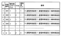
上記電気錠手配表データ42は例えば図5に示すものであり、建物内の区画番号、電気錠コントローラのアドレス、チャネル番号及び電気錠の作動タイプが読み込まれている。
なお、区画番号は、予め工事発注者あるいは工事請負者が建物内で重複しないように採番し、手配表に入力しているものである。
In addition, the
The electric lock
The section number is previously assigned by the construction orderer or the construction contractor so as not to be duplicated in the building and is entered in the arrangement table.
次に、実施の形態1の動作について説明する。各電気錠コントローラ2A、2B…2Nは、接続された各区画の扉に配設された電気錠の作動タイプを上述した手順によって判別すると共に、それぞれのデータベース3A、3B…3Nに自動的に登録する。
Next, the operation of the first embodiment will be described. Each of the
管理装置4からの送信要求があった場合には、それぞれのデータベース3A、3B…3Nのデータを伝送線43を経て管理装置4に送信する。
管理装置4ではデータベース41に収納された電気錠手配表データ42、即ち当初の工事発注時における各区画の扉に配設すべき電気錠の作動タイプと実際に配設された各扉の電気錠の作動タイプとを照合して配設工事ミスの有無を確認し、ミスがあれば警報を発するものである。
When there is a transmission request from the
In the
1、1A…1M 電気錠、 2、2A…2N 電気錠コントローラ、 3A…3N データベース、 4 管理装置、 5A…5M カードリーダ、 10−14 端子、 15 電気錠動作コイル、 16 解錠状態接点、 17 扉状態接点、 20−24 端子、 25 通電スイッチ、 26 接点用直流電源、 27 解錠状態コイル、 28 扉状態コイル、 29 コイル用直流電源、 41 データべース、 42 電気錠手配表データ、 43 伝送線。 1, 1A ... 1M electric lock, 2, 2A ... 2N electric lock controller, 3A ... 3N database, 4 management device, 5A ... 5M card reader, 10-14 terminal, 15 electric lock operation coil, 16 unlocking state contact, 17 Door status contact, 20-24 terminal, 25 Current switch, 26 DC power supply for contact, 27 Unlocked status coil, 28 Door status coil, 29 DC power supply for coil, 41 Database, 42 Electric lock arrangement table data, 43 Transmission line.
Claims (2)
Priority Applications (1)
| Application Number | Priority Date | Filing Date | Title |
|---|---|---|---|
| JP2004117171A JP2005299230A (en) | 2004-04-12 | 2004-04-12 | Controller of electric lock and supervising device |
Applications Claiming Priority (1)
| Application Number | Priority Date | Filing Date | Title |
|---|---|---|---|
| JP2004117171A JP2005299230A (en) | 2004-04-12 | 2004-04-12 | Controller of electric lock and supervising device |
Publications (1)
| Publication Number | Publication Date |
|---|---|
| JP2005299230A true JP2005299230A (en) | 2005-10-27 |
Family
ID=35331115
Family Applications (1)
| Application Number | Title | Priority Date | Filing Date |
|---|---|---|---|
| JP2004117171A Pending JP2005299230A (en) | 2004-04-12 | 2004-04-12 | Controller of electric lock and supervising device |
Country Status (1)
| Country | Link |
|---|---|
| JP (1) | JP2005299230A (en) |
Cited By (3)
| Publication number | Priority date | Publication date | Assignee | Title |
|---|---|---|---|---|
| CN101424939A (en) * | 2007-10-31 | 2009-05-06 | 株式会社日立制作所 | Self-discipline decentralized safety system and control method thereof |
| JP2011214299A (en) * | 2010-03-31 | 2011-10-27 | Sogo Keibi Hosho Co Ltd | Electric lock control device |
| JP2011214300A (en) * | 2010-03-31 | 2011-10-27 | Sogo Keibi Hosho Co Ltd | Electric lock control device and security system |
-
2004
- 2004-04-12 JP JP2004117171A patent/JP2005299230A/en active Pending
Cited By (3)
| Publication number | Priority date | Publication date | Assignee | Title |
|---|---|---|---|---|
| CN101424939A (en) * | 2007-10-31 | 2009-05-06 | 株式会社日立制作所 | Self-discipline decentralized safety system and control method thereof |
| JP2011214299A (en) * | 2010-03-31 | 2011-10-27 | Sogo Keibi Hosho Co Ltd | Electric lock control device |
| JP2011214300A (en) * | 2010-03-31 | 2011-10-27 | Sogo Keibi Hosho Co Ltd | Electric lock control device and security system |
Similar Documents
| Publication | Publication Date | Title |
|---|---|---|
| PL207050B1 (en) | Lock system, lock system device and method of configuring a lock system | |
| JP2005299230A (en) | Controller of electric lock and supervising device | |
| JP5316340B2 (en) | Elevator system | |
| CN1182490C (en) | Arrangement of an entrance unit for a protected area | |
| JP5265261B2 (en) | Entrance / exit management system and program thereof | |
| JPS62258075A (en) | Entry and exit chamber control system | |
| US20120075056A1 (en) | Facility controlling system and method | |
| JP2000163617A (en) | Traffic management device | |
| JP4634198B2 (en) | Entrance / exit management system and entrance / exit management method | |
| JP2012036704A (en) | Access management system | |
| JP2008027140A (en) | Entrance / exit management system | |
| JP5620136B2 (en) | Electric lock control device and security system | |
| JP4580788B2 (en) | Entrance / exit management system | |
| JP2510742B2 (en) | Decentralized access control system | |
| JP2776496B2 (en) | Electric lock device | |
| JP2002260041A (en) | Room entrance/exit managing system with presence-in- room managing function | |
| JP2017220064A (en) | IC card entrance / exit management system and IC card diagnosis method | |
| WO2015013211A2 (en) | Access control system | |
| JP7666408B2 (en) | Safety management system and safety management method for workers in factory workplaces | |
| JP2007026396A (en) | Entrance and exit management system | |
| JP7563284B2 (en) | Traffic Management System | |
| JP2014010464A (en) | Entering/leaving management system | |
| JPH07293070A (en) | Entry / Exit Management Method for Entry / Exit Management System and Entry / Exit Management System | |
| JPH09112094A (en) | 2-wire type entrance / exit device | |
| JP2010086090A (en) | Personal identification information construction system, personal identification information construction method and access management system |