JP2005299225A - Ridge fitting - Google Patents
Ridge fitting Download PDFInfo
- Publication number
- JP2005299225A JP2005299225A JP2004116893A JP2004116893A JP2005299225A JP 2005299225 A JP2005299225 A JP 2005299225A JP 2004116893 A JP2004116893 A JP 2004116893A JP 2004116893 A JP2004116893 A JP 2004116893A JP 2005299225 A JP2005299225 A JP 2005299225A
- Authority
- JP
- Japan
- Prior art keywords
- ridge
- head
- tile
- leg
- fixing
- Prior art date
- Legal status (The legal status is an assumption and is not a legal conclusion. Google has not performed a legal analysis and makes no representation as to the accuracy of the status listed.)
- Granted
Links
- 239000002184 metal Substances 0.000 claims description 39
- 229910052751 metal Inorganic materials 0.000 claims description 39
- 239000002023 wood Substances 0.000 claims description 24
- XEEYBQQBJWHFJM-UHFFFAOYSA-N Iron Chemical compound [Fe] XEEYBQQBJWHFJM-UHFFFAOYSA-N 0.000 claims description 18
- 238000005452 bending Methods 0.000 claims description 11
- 229910052742 iron Inorganic materials 0.000 claims description 9
- 238000003825 pressing Methods 0.000 claims description 6
- 238000004080 punching Methods 0.000 claims description 5
- 238000004519 manufacturing process Methods 0.000 description 10
- 230000000694 effects Effects 0.000 description 4
- ATJFFYVFTNAWJD-UHFFFAOYSA-N Tin Chemical compound [Sn] ATJFFYVFTNAWJD-UHFFFAOYSA-N 0.000 description 2
- 238000000034 method Methods 0.000 description 2
- 238000003466 welding Methods 0.000 description 2
- 235000000396 iron Nutrition 0.000 description 1
- 238000005304 joining Methods 0.000 description 1
- 230000002093 peripheral effect Effects 0.000 description 1
- 230000003014 reinforcing effect Effects 0.000 description 1
- 239000010454 slate Substances 0.000 description 1
- 239000002689 soil Substances 0.000 description 1
- 239000007787 solid Substances 0.000 description 1
Images
Landscapes
- Roof Covering Using Slabs Or Stiff Sheets (AREA)
Abstract
Description
本発明は、屋根の頂部を覆う棟瓦を固定するのに使用される棟金具に関するものであり、特に、使用する瓦の種類に応じて頭部の高さと形状を現場で変更できるようにした棟金具に関するものである。 The present invention relates to a ridge bracket used to fix a ridge tile covering the top of a roof, and in particular, a ridge whose head height and shape can be changed in the field according to the type of tile used. It relates to metal fittings.
従来、屋根の頂部で棟瓦を固定するための器具として棟金具が使用されている。この種の棟金具は、例えば実公平7−32716号公報の図4に従来例として記載されているように、棟瓦固定用木材を保持する上向きのコの字形状を呈する頭部と、この頭部の下に延長される所定長の胴部と、この胴部の下方に左右に開いた状態で取付けられ、屋根への固定に使用される脚部から構成される。 Conventionally, a ridge metal fitting is used as an instrument for fixing a ridge tile at the top of a roof. As shown in FIG. 4 of Japanese Utility Model Publication No. 7-32716, for example, this type of ridge bracket includes a head having an upward U-shape that holds the timber for fixing the ridge tile, It is composed of a trunk portion of a predetermined length that is extended below the section, and legs that are attached to the bottom of the trunk portion so as to open to the left and right and are used for fixing to the roof.
上記実公平7−32716号公報には、実質的な胴部の長さ、したがって、脚部の取付け箇所からの頭部の高さを、瓦の種類などに応じて現場で調整可能とした棟金具が開示されている。すなわち、図9の斜視図に示すように、上向きのコの字形状を呈する頭部51の下方に一定長の胴部52が取付けられ、この胴部52の下方にさらに脚部53が取付けられる。この脚部53を構成する2枚の脚板53a,53bは、使用前は、図中に点線で示すように、互いに真っ直ぐな閉脚状態に保たれる。脚板53a,53bのそれぞれには、その長さ方向に離散させて幅方向の切り欠き53cが複数形成されている。
In the above-mentioned No. 7-32716, a ridge in which the substantial length of the body portion, and hence the height of the head from the mounting position of the leg portion, can be adjusted on the site according to the type of roof tiles, etc. A fitting is disclosed. That is, as shown in the perspective view of FIG. 9, a fixed-
この棟金具の使用時には、曲げ剛性を減少させた切り欠き部53cの形成箇所で、2枚の脚板を相互に離間するように湾曲させることにより、図9に実線で示すような開脚の状態にする。この開脚の状態で、釘穴53dを通して釘を打ち込むことによりこの棟金具を屋根の頂部に固定する。次いで、図中の矢印で示すZ軸方向に延長される棟瓦固定用木材が頭部51に保持され、釘穴51cを通して打ち込まれる釘によりこの頭部51に固定される。この棟金具は、屋根の頂部の稜線方向に沿って、適宜な間隔で複数設置される。
When this ridge metal fitting is used, the two leg plates are curved so as to be spaced apart from each other at the location where the cutout portion 53c with reduced bending rigidity is formed, so that the state of the open leg as shown by the solid line in FIG. To. In the state of this open leg, this ridge metal fitting is fixed to the top of the roof by driving a nail through the nail hole 53d. Next, the roof tile fixing wood extended in the Z-axis direction indicated by the arrow in the figure is held by the
この棟金具は、製造コストを減少させるために、1枚の金属板を折り曲げて作られる。すなわち、図10に示すように、打ち抜きとプレス加工によって成型した1枚の金属板を点線に沿って折り曲げることにより、図9に示したような立体形状の棟金具が作成される。なお、図10において、51aは頭部の底板、51bは頭部の側板である。なお、図10において、幅方向への切り欠きや釘穴は、便宜上、図示が省略されている。 This ridge metal fitting is made by bending a single metal plate in order to reduce manufacturing costs. That is, as shown in FIG. 10, a solid metal ridge fitting as shown in FIG. 9 is created by bending a single metal plate formed by punching and pressing along a dotted line. In FIG. 10, 51a is a bottom plate of the head, and 51b is a side plate of the head. In FIG. 10, illustrations of notches and nail holes in the width direction are omitted for convenience.
図9と図10に示した頭部の高さを調整できる従来の棟金具は、連結部52aの長さで決まる固定長の胴部52の下方に、可変長の脚部53を取付けた構造となっている。このため、図9に示すように1枚の金属板を折り曲げて作るという方法を採用する限り、胴部52の長さをゼロにすることができないという問題がある。この胴部をゼロにしたいという要求は、プレハブ住宅用の薄型のスレート瓦を葺く場合などにしばしば生じる。コの字形状の頭部と脚部を別々に作成し、溶接やネジ止めによって相互を連結する製造方法に変更すれば、胴部を省略でき、従ってその長さをゼロにできる。しかしながら、この製造方法では、図10に示すように打ち抜きとプレス加工によって成型した1枚の金属板を折り曲げて立体構造を完成させるという製造方法に比べて、溶接やネジ止めなどの接合工程が必要になり、製造コストが上昇するという問題がある。
9 and 10 has a structure in which a variable-
また、従来の棟金具は、棟瓦固定用木材の保持という単一の機能しか備えていない。すなわち、貫板など種々の部品が固定される屋根の頂部に設置されるという利点を十分に活かしきれていないという問題もある。さらに、従来の棟金具の構造では、棟瓦を止めるために上方から下方に向けて打ち込まれる釘が長すぎて保持中の棟瓦固定用木材を貫通した時に、頭部の底板に当たってしまい固定の機能が阻害されてしまうという問題があった。さらに、従来の棟金具では、棟瓦の固定専用となっており、棟瓦ではなく棟トタンを固定する用途には使用できないという問題がある。 Moreover, the conventional ridge metal fitting has only a single function of holding the timber for fixing the ridge tile. That is, there is also a problem that the advantage of being installed on the top of the roof to which various parts such as a through plate are fixed cannot be fully utilized. Further, in the conventional structure of the ridge bracket, when the nail that is driven from the top to the bottom to stop the ridge tile is too long and penetrates the ridge tile fixing wood being held, it hits the bottom plate of the head and has a function of fixing. There was a problem of being obstructed. Furthermore, the conventional ridge brackets are exclusively used for fixing ridge tiles, and there is a problem that they cannot be used for fixing ridge irons instead of ridge tiles.
従って、本発明の一つの目的は、頭部の高さを胴部がゼロの場合も含めて調整可能な棟金具、特に、1枚の金属板を折り曲げて立体構造を完成させる製造方法が適用可能な棟金具を提供することにある。本発明の他の目的は、棟瓦固定用木材を保持するという従来の機能に加えて、他の部品を保持するという新たな機能も兼ねた多機能の棟金具を提供することにある。本発明のさらに他の目的は、上方から打ち込まれる長すぎる釘に対して逃げの空間を提供可能な棟金具を提供することにある。本発明のさらに他の目的は、棟瓦ではなく棟トタンを設置する場合にも適用できる万能の棟金具を提供することにある。 Therefore, one object of the present invention is to apply a ridge bracket that can be adjusted even when the body height is zero, particularly a manufacturing method for folding a single metal plate to complete a three-dimensional structure. It is to provide a possible ridge bracket. Another object of the present invention is to provide a multifunctional ridge metal fitting which also has a new function of holding other components in addition to the conventional function of holding timber fixing wood. Still another object of the present invention is to provide a ridge bracket capable of providing a clearance space for a too long nail driven from above. Still another object of the present invention is to provide a universal ridge metal fitting that can be applied to a case where a ridge iron is installed instead of a ridge tile.
上記従来技術の課題を解決する本発明の棟金具は、底面部と側面部とから成り棟瓦固定用木材を保持する頭部と、この頭部の底面部から下方に向けて延長されこの延長方向に離間して形成される幅方向への切り欠きの箇所において棟瓦固定用木材の延長方向と直交する方向に互いに離間するように折り曲げられる1対の脚板から成る脚部とを備えている。そして、上頭部の底面部は、保持対象の棟瓦固定用木材の長手方向と幅方向とに沿って適宜な距離離間しかつこの底面部の中央部分に相互の連結部分を有する第1,第2の部分から成り、上記頭部の側面部は底面部に対して折り曲げ自在に連結されると共に、棟瓦固定用木材の長手方向に沿って互いに分離された複数の側板から成り、上記1対の脚板は頭部の底面部の第1,第2の部分の相互の連結部分を除く箇所に連結されている。 The ridge metal fitting of the present invention that solves the above-described problems of the prior art is composed of a bottom portion and a side portion that holds the roof tile fixing wood, and extends downward from the bottom portion of the head. Leg portions made of a pair of leg plates that are bent so as to be separated from each other in a direction orthogonal to the extending direction of the timber for fixing the roof tile at the location of the notches in the width direction formed apart from each other. The bottom surface portion of the upper head is separated by an appropriate distance along the longitudinal direction and the width direction of the ridge tile fixing wood to be held, and has a first and a second connection portion at the center portion of the bottom surface portion. The side portion of the head is foldably connected to the bottom portion, and includes a plurality of side plates separated from each other along the longitudinal direction of the roof tile fixing wood. The leg plate is connected to a portion excluding the connecting portion of the first and second portions of the bottom surface of the head.
本発明の棟金具においては、1対の脚板が、底面部の中央部分の連結部分を除く箇所に連結されているので、頭部の高さを胴部がゼロの場合をもめて調整できる。特に、打ち抜きとプレス加工によって成型された1枚の金属板を折り曲げて立体構造を完成する製造方法が採用でき、製造コストが低減されるという効果が奏される。 In the ridge bracket according to the present invention, the pair of leg plates is connected to the portion excluding the connecting portion of the central portion of the bottom portion, so that the height of the head can be adjusted even when the trunk portion is zero. In particular, it is possible to employ a manufacturing method in which a three-dimensional structure is completed by bending a single metal plate formed by punching and pressing, and the manufacturing cost is reduced.
また、頭部の底面部の第1,第2の部分に連なる側面部は、棟瓦固定用木材の長手方向に沿って互いに分離された複数の側板から構成されている。このため、棟瓦固定用木材の保持に2個の側板を割り当て、残りの側板を他の部品の保持用に割り当てることが可能になるという効果が奏される。 Moreover, the side part connected to the 1st, 2nd part of the bottom face part of a head is comprised from the some side plate isolate | separated mutually along the longitudinal direction of the timber fixing wood. For this reason, it is possible to allocate two side plates for holding the roof tile fixing wood and to allocate the remaining side plates for holding other components.
さらに、本発明の棟金具では、頭部の底面部が保持対象の棟瓦固定用木材の長手方向と幅方向に沿って適宜な距離離間しかつ頭部の棟瓦固定用木材の長手方向の中央部において互いに連結される第1,第2の部分から構成されので、第1,第2の部分の前後に逃げ用の空間が形成される。この結果、棟瓦を止める際に釘が長すぎて保持中の棟瓦固定用木材を貫通した場合、この逃げ用の空間に釘の先端部を誘導することにより、釘の先端部が底面部に衝突する事態を回避できるという効果が奏される。 Further, in the ridge metal fitting of the present invention, the bottom portion of the head is separated by an appropriate distance along the longitudinal direction and the width direction of the ridge tile fixing wood to be held, and the longitudinal central portion of the ridge tile fixing wood of the head Since the first and second portions are connected to each other in FIG. 1, escape spaces are formed before and after the first and second portions. As a result, if the nail is too long when the ridge tile is stopped and penetrates the holding timber fixing wood, the tip of the nail collides with the bottom surface by guiding the tip of the nail into this escape space. The effect of being able to avoid the situation to do is produced.
さらに本発明の棟金具は、頭部の側面部がその底面部に対して折り曲げ自在に連結されているので、複数の側板のすべてをほぼ水平方向に延長させることにより、棟瓦の保持用としてだけではなく、棟トタンの保持用としても使用することができる。 Furthermore, since the side wall of the head of the ridge bracket of the present invention is connected to the bottom surface of the ridge bracket so as to be foldable, by extending all of the plurality of side plates in a substantially horizontal direction, only for holding the ridge tile. Rather, it can also be used for holding a ridged tin.
本発明の一つの好適な実施の形態によれば、棟金具が打ち抜きとプレス加工によって成型された1枚の金属板を折り曲げることによって立体構造を完成するという製造方法が適用されるので、安価な製造コストの棟金具を提供できるという効果が奏される。 According to one preferred embodiment of the present invention, a manufacturing method is applied in which a three-dimensional structure is completed by bending a metal plate formed by punching and pressing a ridge metal fitting, so that it is inexpensive. There is an effect that it is possible to provide a ridge bracket at a manufacturing cost.
本発明の他の好適な実施の形態によれば、頭部の側面部の複数の側板のうち少なくとも二つは、斜め下方に折り曲げられて貫板に固定されることにより、棟瓦固定用木材保持の機能に加えて貫板保持の機能も有するという効果が奏される。 According to another preferred embodiment of the present invention, at least two of the plurality of side plates of the side surface portion of the head are bent obliquely downward and fixed to the through plate, thereby holding the timber fixing wood holding member. In addition to this function, there is an effect that it also has a function of holding a through plate.
本発明のさらに他の好適な実施の形態によれば、1対の脚板のそれぞれは、連結部の下方において拡幅部分が形成され、この拡幅部分に屋根への固定用釘穴が形成されることにより、この棟金具を3〜4cmの比較的小さな幅の垂木の上に固定することが可能になるという効果が奏される。 According to still another preferred embodiment of the present invention, each of the pair of leg plates has a widened portion formed below the connecting portion, and a nail hole for fixing to the roof is formed in the widened portion. Thus, the effect that it becomes possible to fix the ridge bracket on a rafter having a relatively small width of 3 to 4 cm is exhibited.
さらに本発明のさらに他の好適な実施の形態によれば、頭部の複数の側板のすべてをほぼ水平状態に保つことにより、棟瓦ではなく棟トタンの保持用として使用される。 According to still another preferred embodiment of the present invention, all of the plurality of side plates of the head are kept in a substantially horizontal state, so that they are used for holding a ridged tin rather than a ridged roof tile.
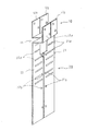
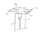
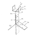
図1は本発明の一実施例の棟金具の構成を示す斜視図である。この実施例の棟金具は概ね上向きのコの字形状を呈する頭部10と、この頭部10からその下方に向けて延長される脚部20とから構成されている。脚部20を構成する2枚の脚板21と22には、幅方向への切り欠き21a,22aが脚板21,22のそれぞれの長手方向に適宜な距離で離間して複数形成されている。
FIG. 1 is a perspective view showing the structure of a ridge fitting according to an embodiment of the present invention. The ridge bracket of this embodiment is composed of a
図2の平面図を参照すると、頭部10の底面部11は、矢印で示す棟瓦固定用木材の長手方向(Z軸)に沿って距離ΔLだけ離間すると共に、この長手方向に直交する棟瓦固定用木材の幅方向にΔWだけ離間した第1,第2の部分11a,11bと、この底面部11の中央部分において第1,第2の部分11a,11bを連結する相互の連結部分11cとから構成されている。底面部11の第1の部分11aに折り曲げ自在に連結される側面部12は、棟瓦固定用木材の長手方向に沿って分離された2個の側板12a,12bから構成されている。同様に、底面部11の第2の部分11bに折り曲げ自在に連結される側面部13は、棟瓦固定用木材の長手方向に沿って分離された2個の側板13a,13bから構成されている。脚部20の2枚の脚板21と22は、底面部11の第1,第2の部分の相互の連結部分11cを除く箇所に折り曲げ自在に連結されている。
Referring to the plan view of FIG. 2, the
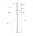
図1、図2に示した本実施例の棟金具は、図3に示すように打ち抜き・プレス成型された1枚の金属板を点線のまわりに折り曲げることによって作成される。図3では、脚板21と22をそれぞれ、点線で示した底面部の第1,第2の部分11a,11bとの境界線のまわりに紙面の裏側に向けて角度90°だけ折り曲げ、4枚の側板12a,12b,13a,13bを点線で示した底面部の第1,第2の部分11a,11bとの境界線のまわりに紙面の表側に向けて角度90°だけ折り曲げることにより、図1と図2に示した立体構造の棟金具が作成される。
The ridge bracket of the present embodiment shown in FIGS. 1 and 2 is produced by bending a single metal plate that has been stamped and press-molded as shown in FIG. 3 around a dotted line. In FIG. 3, each of the
なお、図3では便宜上、打ち抜きとプレス加工によって一時に形成される複数の切り欠きと釘穴の図示が省略されている。また、底面部11と側面部12,13間の点線で示す折り曲げ自在な連結箇所には、厚みを減らして曲げ剛性を低下させるための溝が形成されているが、便宜上この溝の図示が省略されている。
In FIG. 3, for the sake of convenience, the illustration of a plurality of notches and nail holes formed at a time by punching and pressing is omitted. In addition, a groove for reducing the thickness and reducing the bending rigidity is formed at a foldable connecting portion indicated by a dotted line between the
図1を参照すると、脚板21と22は頭部10からあるていど離れた箇所で幅が拡大されるという拡幅が行われている。そして、この拡幅部分に屋根への固定用釘穴21b,22bが形成される。これは、この棟金具の脚部を釘で固定する垂木の幅が典型的には3cm〜4cmの範囲であることを考慮したものである。すなわち、脚板21,22に形成した釘穴の間隔が垂木の幅よりも大きくなって、垂木への釘打ちによる固定ができなくなるという問題を解決するための構成である。すなわち、脚板21,22に拡幅部分を形成し、この拡幅部分に釘穴21b,22bを形成することにより、釘穴21bと22bとの間隔を、通常3cm〜4cmという垂木の幅よりも小さな値に設定したものである。
Referring to FIG. 1, the
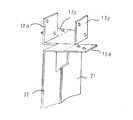
図4は、頭部の形状の一例を示す斜視図である。この頭部の形状は、頭部の側板12a,13bを直立させて棟瓦固定用木材の保持用に割り当てると共に、側板13a,12bをほぼ水平状態に保つことにより、これらの側板13a,12bを貫板などの平板の保持用に割り当てるようにした場合のものである。これについては、図6を参照しながら後述する。
FIG. 4 is a perspective view showing an example of the shape of the head. The shape of the head is such that the
図5は、頭部の他の形状の一例を示す斜視図である。この頭部の形状は、頭部の全ての側板12a,12b,13a,13bをほぼ水平状態に保持することにより、全ての側板を棟トタンの保持用に割り当てるようるした場合のものである。これについては、図7を参照しながら後述する。
FIG. 5 is a perspective view showing an example of another shape of the head. The shape of the head is that in the case where all the side plates are allocated for holding the wing iron by holding all the
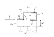
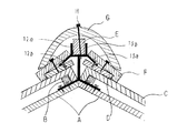
図6は、この実施例の棟金具を屋根の頂部に設置して棟瓦の保持に使用する様子を他の部品との関連と共に示す断面図である。まず、頭部から下方の開脚部分までの長さが所望の値となるように、開脚状態にしたこの実施例の棟金具が幅3〜4cmの垂木Aに釘で固定される。次いで、瓦桟Bと瓦Cを順次取付け、この瓦Cの上に貫板、平割板などの平板Dを載置する。この平板Dに対して斜め下方に折り曲げた側板12bと13aの釘穴を通してネジを挿入し、螺合させることにより、平板Dを棟金具の側板12bと13aに固定する。
FIG. 6 is a cross-sectional view showing the manner in which the ridge metal fitting of this embodiment is installed on the top of the roof and used for holding the ridge tile together with other components. First, the ridge bracket of this embodiment in an open leg state is fixed to the rafter A having a width of 3 to 4 cm with a nail so that the length from the head to the lower leg portion becomes a desired value. Next, the tile rail B and the tile C are sequentially attached, and a flat plate D such as a through plate or a flat plate is placed on the tile C. The flat plate D is fixed to the
次に、棟金具の頭部20に、棟瓦固定用木材Eを載置し、側板12a,13bに形成されている釘穴を通して釘を打ち込むことにより、棟瓦固定用木材Eを棟金具の頭部に固定する。こののち、平板Dの上に面土用瓦Fが載置され、この面土用瓦Fに予め作られている釘穴を通して釘が打ち込まれることにより、面土用瓦Fが平板Dに固定される。続いて、面土用瓦Fの上に棟瓦Gを載置する。最後に、棟瓦Gの頂部に形成されている釘穴を通して、棟瓦固定用木材Eに向けて長目の釘Hが下方に向けて打ち込まれる。
Next, the roof tile fixing wood E is placed on the
この際、図6に例示するように、釘Hが長すぎると、その先端部が棟金具の頭部の底板に衝突してしまい、棟瓦Gの固定に支障が生じる。この実施例の棟金具では、底面部11の第1,第2の部分11a,11bが棟瓦固定用木材の長手方向と幅方向にそれぞれ、ΔL,ΔWだけ離間しているため、釘の先端部を逃がすための合計2ΔL×ΔWの面積の空間が、底面部11の周辺部に形成される。この逃げの空間に向けて、釘を斜めに打ち込むことにより、釘が長すぎる場合の上記問題を解決することができる。
At this time, as illustrated in FIG. 6, if the nail H is too long, the tip of the nail H collides with the bottom plate of the head of the ridge metal fitting, which causes a problem in fixing the ridge tile G. In the ridge metal fitting of this embodiment, the first and
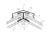
図7は、この実施例の棟金具を屋根の頂部に設置し、棟瓦ではなく棟トタンの保持に使用する様子を他の部品との関連と共に示す断面図である。この例では、頭部のすべての側板をほぼ水平状態に保った頭部の形状の棟金具が使用される。瓦桟Bと瓦Cを順次取付けるところまでは、図6に関して説明したと同様である。こののち、貫板などの平板Dに対して側面部の側板12a,12b,13a,13bの釘穴を通してネジを挿入し、螺合させることにより、平板Dを棟金具の側面部の側板12a,12b,13a,13bに固定する。次いで、棟金具の上に棟トタンIを被せ、棟トタンを通して平板Dに釘を打ち込むことにより、平板Dに棟トタンIを固定する。
FIG. 7 is a cross-sectional view showing a state in which the ridge metal fitting of this embodiment is installed on the top of the roof and is used for holding the ridge iron instead of the ridge tile together with other components. In this example, a ridge fitting in the shape of a head in which all side plates of the head are kept in a substantially horizontal state is used. The steps up to the point where the roof rail B and the roof tile C are sequentially attached are the same as described with reference to FIG. After that, screws are inserted through the nail holes of the
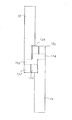
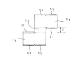
図8は、本発明の他の実施例の棟金具の構成を示す平面図である。この実施例では、底面部11の第1の部分11aと、第2の部分11bとを中心部分で連結する連結部11cが、適宜な幅uを有している。この図5の構成を連結部の幅uが適宜な値を有する一般的な構成とすると、図1〜図3を参照して説明した最初の実施例は連結部分の幅uがゼロとなるような特殊な構成に該当する。
FIG. 8 is a plan view showing a configuration of a ridge fitting according to another embodiment of the present invention. In this embodiment, the connecting
以上、頭部の底板部を平坦にする構成を例示した。しかしながら、底面部11の連結部11cに断面が半円形状で棟瓦固定用木材の長手方向に延長される溝を形成し、この溝に断面が円柱形状の鉄筋などを保持させる機構を付加することもできる。
As mentioned above, the structure which makes the bottom plate part of a head flat is illustrated. However, a groove that has a semicircular cross section and extends in the longitudinal direction of the roof tile fixing wood is formed in the connecting
10 頭部
11 底面部
11a,11b 底面部の第1, 第2の部分
12a,12b,13a,13b 側面部の側板
20 脚部
21,22 脚板
21a,22a 切り欠き
21b,22b 釘穴
A 垂木
C 瓦
D 貫板などの平板
E 棟瓦固定用木材
F 面土用瓦
G 棟瓦
H 釘
I 棟トタン
u 底面部の連結部の幅
10 heads
11 Bottom
11a, 11b The first and second parts of the bottom
12a, 12b, 13a, 13b Side plate on the side
20 legs
21,22 Leg plate
21a, 22a Notch
21b, 22b Nail hole
A rafter
C roof tile
D Flat plate such as through plate
E Timber fixing wood
F tile for tile
G roof tile
H nails
I ridged iron u Width of connecting part at bottom
Claims (5)
前記頭部の底面部は、前記保持対象の棟瓦固定用木材の長手方向と幅方向とに沿って適宜な距離離間しかつこの底面部の中央部分に相互の連結部分を有する第1,第2の部分から成ることと、
前記側面部は前記底面部に対して折り曲げ自在に連結されると共に、前記棟瓦固定用木材の長手方向に沿って互いに分離された複数の側板から成ることと、
前記1対の脚板は、前記底面部の第1,第2の部分の相互の連結部分を除く箇所に連結されたことを特徴とする棟金具。 A head portion composed of a bottom surface portion and a side surface portion for holding the timber for fixing the roof tile, and a notch in the width direction formed extending downward from the bottom surface portion of the head and spaced apart in the extending direction In the ridge bracket comprising a pair of leg plates that are bent so as to be separated from each other in a direction perpendicular to the extending direction of the ridge tile fixing wood,
The bottom surface of the head is spaced apart by an appropriate distance along the longitudinal direction and the width direction of the ridge tile fixing wood to be held, and has a first and second connecting portion at the center of the bottom surface. Consisting of
The side surface portion is connected to the bottom surface portion so as to be foldable, and includes a plurality of side plates separated from each other along a longitudinal direction of the timber fixing wood,
The pair of leg plates is connected to a portion of the bottom portion excluding the mutual connecting portion of the first and second portions.
前記棟金具は、打ち抜きとプレス加工によって成型された1枚の金属板を折り曲げることにより完成させた立体構造を有することを特徴とする棟金具。 In claim 1,
The ridge metal fitting has a three-dimensional structure completed by bending a single metal plate formed by punching and pressing.
前記頭部の側面部の複数の側板のうち少なくとも二つは、斜め下方に折り曲げられて貫板に固定されることを特徴とする棟金具。 In either claim 1 or 2,
At least two of the plurality of side plates of the side portion of the head are bent obliquely downward and fixed to the through plate.
前記頭部の側面部の複数の側板はすべてほほ水平方向に延長され、棟トタンを保持するための平板の保持に使用されることを特徴とする棟金具。 In any one of Claims 1 thru | or 3,
A plurality of side plates of the side portion of the head are all extended in a substantially horizontal direction, and are used for holding a flat plate for holding a ridge iron.
The ridge according to any one of claims 1 to 4, wherein the pair of leg portions are formed with a widened portion below the connecting portion, and a nail hole for fixing to the roof is formed in the widened portion. Hardware.
Priority Applications (1)
| Application Number | Priority Date | Filing Date | Title |
|---|---|---|---|
| JP2004116893A JP3880979B2 (en) | 2004-04-12 | 2004-04-12 | Ridge bracket |
Applications Claiming Priority (1)
| Application Number | Priority Date | Filing Date | Title |
|---|---|---|---|
| JP2004116893A JP3880979B2 (en) | 2004-04-12 | 2004-04-12 | Ridge bracket |
Publications (2)
| Publication Number | Publication Date |
|---|---|
| JP2005299225A true JP2005299225A (en) | 2005-10-27 |
| JP3880979B2 JP3880979B2 (en) | 2007-02-14 |
Family
ID=35331110
Family Applications (1)
| Application Number | Title | Priority Date | Filing Date |
|---|---|---|---|
| JP2004116893A Expired - Fee Related JP3880979B2 (en) | 2004-04-12 | 2004-04-12 | Ridge bracket |
Country Status (1)
| Country | Link |
|---|---|
| JP (1) | JP3880979B2 (en) |
Cited By (2)
| Publication number | Priority date | Publication date | Assignee | Title |
|---|---|---|---|---|
| JP2008156830A (en) * | 2006-12-21 | 2008-07-10 | Asahi Fiber Glass Co Ltd | Mounting structure for crosspieces and support structure for floor insulation |
| JP2010281136A (en) * | 2009-06-05 | 2010-12-16 | Kmew Co Ltd | Building receiving bracket and plate material for building building receiving bracket |
-
2004
- 2004-04-12 JP JP2004116893A patent/JP3880979B2/en not_active Expired - Fee Related
Cited By (2)
| Publication number | Priority date | Publication date | Assignee | Title |
|---|---|---|---|---|
| JP2008156830A (en) * | 2006-12-21 | 2008-07-10 | Asahi Fiber Glass Co Ltd | Mounting structure for crosspieces and support structure for floor insulation |
| JP2010281136A (en) * | 2009-06-05 | 2010-12-16 | Kmew Co Ltd | Building receiving bracket and plate material for building building receiving bracket |
Also Published As
| Publication number | Publication date |
|---|---|
| JP3880979B2 (en) | 2007-02-14 |
Similar Documents
| Publication | Publication Date | Title |
|---|---|---|
| US7788873B2 (en) | Gable end brace | |
| KR102124775B1 (en) | Non-welding truss | |
| US9689173B2 (en) | Structure attached with vibration control device | |
| JP2017508905A (en) | Shear tie system for ventilated roof building | |
| US20130055656A1 (en) | Gable overhang structure | |
| JP3880979B2 (en) | Ridge bracket | |
| AU2008233436B2 (en) | A bracket | |
| JP5172607B2 (en) | Joint structure of flat column and beam | |
| US20080295447A1 (en) | Method of reinforcing a corrugated steel floor panel | |
| KR102551781B1 (en) | Fixed Bracket Of Structure Truss | |
| JP3877221B2 (en) | Inner wall panel fixing bracket for inner corner and inner wall panel fixing structure in inner corner | |
| KR200413696Y1 (en) | Support for Wall Panels | |
| EP2607561A2 (en) | Improved hanger | |
| JP3050171U (en) | Joining fittings for wooden buildings | |
| JP3015820U (en) | Mounting structure for ceiling panels of wooden buildings | |
| JP6889547B2 (en) | Construction board construction structure and construction board construction method | |
| RU56977U1 (en) | CONNECTING DETAIL FOR CONNECTING LONG-DIMENSIONAL ELEMENTS AND PREPARING THE CONNECTING DETAIL | |
| SE427127B (en) | SPONTATIC WOODWORK AND WAY TO ASSEMBLY THIS | |
| JPH0726516Y2 (en) | Spacer between existing wall and new wall | |
| JP4070019B2 (en) | Rafter fixing member | |
| JP4309809B2 (en) | Building floor joists | |
| JP2000336818A (en) | Fixing structure of floor base material | |
| JP3668541B2 (en) | Building material connection bracket | |
| JPS6035691Y2 (en) | eaves equipment | |
| JP2009007770A (en) | Wood-frame construction method and wood-frame construction structure |
Legal Events
| Date | Code | Title | Description |
|---|---|---|---|
| A977 | Report on retrieval |
Free format text: JAPANESE INTERMEDIATE CODE: A971007 Effective date: 20060529 |
|
| A131 | Notification of reasons for refusal |
Free format text: JAPANESE INTERMEDIATE CODE: A131 Effective date: 20060606 |
|
| A521 | Written amendment |
Free format text: JAPANESE INTERMEDIATE CODE: A523 Effective date: 20060707 |
|
| A131 | Notification of reasons for refusal |
Free format text: JAPANESE INTERMEDIATE CODE: A131 Effective date: 20060808 |
|
| A521 | Written amendment |
Free format text: JAPANESE INTERMEDIATE CODE: A523 Effective date: 20060916 |
|
| TRDD | Decision of grant or rejection written | ||
| A01 | Written decision to grant a patent or to grant a registration (utility model) |
Free format text: JAPANESE INTERMEDIATE CODE: A01 Effective date: 20061031 |
|
| A61 | First payment of annual fees (during grant procedure) |
Free format text: JAPANESE INTERMEDIATE CODE: A61 Effective date: 20061108 |
|
| R150 | Certificate of patent (=grant) or registration of utility model |
Free format text: JAPANESE INTERMEDIATE CODE: R150 |
|
| LAPS | Cancellation because of no payment of annual fees |