JP2005299112A - Safety rod for roof work - Google Patents
Safety rod for roof work Download PDFInfo
- Publication number
- JP2005299112A JP2005299112A JP2004113195A JP2004113195A JP2005299112A JP 2005299112 A JP2005299112 A JP 2005299112A JP 2004113195 A JP2004113195 A JP 2004113195A JP 2004113195 A JP2004113195 A JP 2004113195A JP 2005299112 A JP2005299112 A JP 2005299112A
- Authority
- JP
- Japan
- Prior art keywords
- safety
- rod
- roof
- rope
- work
- Prior art date
- Legal status (The legal status is an assumption and is not a legal conclusion. Google has not performed a legal analysis and makes no representation as to the accuracy of the status listed.)
- Pending
Links
- 238000005452 bending Methods 0.000 claims description 5
- 239000002184 metal Substances 0.000 description 5
- 239000000463 material Substances 0.000 description 4
- 238000000465 moulding Methods 0.000 description 4
- 238000004873 anchoring Methods 0.000 description 3
- 230000001174 ascending effect Effects 0.000 description 2
- 238000010276 construction Methods 0.000 description 2
- 238000004519 manufacturing process Methods 0.000 description 2
- 239000010454 slate Substances 0.000 description 2
- 229910001220 stainless steel Inorganic materials 0.000 description 2
- 239000010935 stainless steel Substances 0.000 description 2
- 235000017166 Bambusa arundinacea Nutrition 0.000 description 1
- 235000017491 Bambusa tulda Nutrition 0.000 description 1
- 241001330002 Bambuseae Species 0.000 description 1
- OKTJSMMVPCPJKN-UHFFFAOYSA-N Carbon Chemical compound [C] OKTJSMMVPCPJKN-UHFFFAOYSA-N 0.000 description 1
- 235000015334 Phyllostachys viridis Nutrition 0.000 description 1
- 239000011425 bamboo Substances 0.000 description 1
- 229910052799 carbon Inorganic materials 0.000 description 1
- 230000009194 climbing Effects 0.000 description 1
- 238000005242 forging Methods 0.000 description 1
- 239000003365 glass fiber Substances 0.000 description 1
- 238000009434 installation Methods 0.000 description 1
- 238000012423 maintenance Methods 0.000 description 1
- 238000000034 method Methods 0.000 description 1
- 230000002265 prevention Effects 0.000 description 1
- 238000004080 punching Methods 0.000 description 1
- 230000008439 repair process Effects 0.000 description 1
- 239000011347 resin Substances 0.000 description 1
- 229920005989 resin Polymers 0.000 description 1
- 238000004804 winding Methods 0.000 description 1
- 239000002023 wood Substances 0.000 description 1
Images
Landscapes
- Emergency Lowering Means (AREA)
Abstract
Description
本発明は、命綱を係止するための安全索係止部が設けられた傾斜屋根面における作業者の安全を確保するために用いて好適な屋根作業用安全棒に関する。 The present invention relates to a safety rod for roof work suitable for securing the safety of an operator on an inclined roof surface provided with a safety rope locking portion for locking a lifeline.
建物の屋根は、施工後の経年変化に応じてメンテナンスを行ったり、屋根施工後にアンテナの取付、交換作業を行う場合もある。この場合、屋根職人やアンテナ取付作業者が屋根に上って、資材の持ち上げや補修、取付、交換作業を行うのであるが、特に傾斜屋根面の場合は滑りやすく、高所作業であるため、作業者自体の身体確保に留意する必要がある。 The roof of a building may be subjected to maintenance according to the secular change after construction, or the antenna may be attached or replaced after the roof construction. In this case, the roofer or antenna installation worker goes up to the roof and lifts, repairs, installs, and replaces the material. It is necessary to pay attention to securing the worker's own body.
一般に、上記の屋根上作業者は、命綱と称される安全索によって、身体の安全が確保される。例えば下記特許文献lには、瓦屋根頂部の棟瓦の下面に沿って、半円形状の安全金具本体を固定し、該安全金具本体の棟瓦の下面からの突出腕部に設けた把手に作業者の安全索を係止させる安全金具が提案されている。また、予め複数の安全具を傾斜屋根面の適所に固定しておくことで、以後の屋根作業時には、当該安全具により作業者の安全確保が可能となるようにした屋根作業用安全具及び安全構造も提案されている。
傾斜屋根面では、任意な作業領域で命綱が係止される必要がある。そのために、傾斜屋根面に所定の間隔で複数の屋根作業用安全具の配設された上記の安全構造も提案されている。ところが、命綱の長さは、作業性の点からも限界がある。また、この命綱を一つの屋根作業用安全具に係止した状態で、他の屋根作業用安全具に係止が可能となる間隔で複数の屋根作業用安全具を配設すれば、その数が膨大となり、コスト面でも現実的でなくなる。したがって、実際には、現在命綱を係止している安全索係止部から、他の安全索係止部へ命綱の掛け替えを行う際には、一旦係止中の現在の安全索係止部から命綱を外し、他の安全索係止部まで傾斜屋根面を昇って命綱を他の安全索係止部に係止しなければならなかった。そのため、例えば命綱を現在係止中の安全索係止部から外して他の安全索係止部へ掛け替えるまでの間に、命綱未係止状態が発生し、安全性の低下する空白時間が発生した。 On an inclined roof surface, the lifeline needs to be locked in an arbitrary work area. Therefore, the above-described safety structure in which a plurality of roofing safety devices are arranged at predetermined intervals on the inclined roof surface has also been proposed. However, the length of the lifeline is limited in terms of workability. In addition, when this lifeline is locked to one roofing work safety device and a plurality of roofing work safety devices are arranged at intervals that can be locked to other roofing work safety devices, the number thereof Becomes enormous and not realistic in terms of cost. Therefore, in actuality, when changing the lifeline from the safety line locking part currently locking the lifeline to another safety line locking part, the current safety line locking part once locked The lifeline had to be removed from the safety line, and the lifeline was locked to the other safety line locking part by ascending the inclined roof surface to the other safety line locking part. Therefore, for example, when the lifeline is removed from the currently secured safety line locking part and replaced with another safety line locking part, the lifeline non-locked state occurs, and the blank time when the safety is lowered Occurred.
本発明は上記状況に鑑みてなされたもので、複数の屋根作業用安全具が配設された傾斜屋根面での作業において、命綱未係止状態での安全性低下が防止できる屋根作業用安全棒を提供し、もって、命綱未係止状態での安全性の確保を図ることを目的とする。 The present invention has been made in view of the above situation, and roof work safety that can prevent a decrease in safety when the lifeline is not locked in a work on an inclined roof surface provided with a plurality of roof work safety devices. The purpose is to provide a bar and to ensure safety when the lifeline is not locked.
次に、上記の課題を解決するための手段を、実施の形態に対応する図面を参照して説明する。
本発明の請求項1記載の屋根作業用安全棒100は、傾斜屋根面21に固定され環状の安全索係止部23a(25a)を有する屋根作業用安全具23(25)に引っ掛けて使用する屋根作業用安全棒100であって、
棒本体27と、
該棒本体27の一端に設けられるグリップ部29と、
前記棒本体27の他端に設けられ先端31cが該棒本体27の一端側へ曲げられて前記安全索係止部23a(25a)に引っ掛け可能となった鉤状のフック部31と、
該フック部31に始端33aが締結固定されるとともに終端33bが自由端となる親綱33と、
を具備したことを特徴とする。
Next, means for solving the above problems will be described with reference to the drawings corresponding to the embodiments.
The
A
A
A hook-
A
It is characterized by comprising.
この屋根作業用安全棒100では、安全索係止部23a(25a)が所定間隔で設けられた傾斜屋根面21での作業中に、作業者47が例えば他の作業場所へ移動するため、現在命綱45を係止している安全索係止部23a(25a)から、他の安全索係止部23a(25a)へ命綱45の掛け替えを行う際に、先ず、グリップ部29が把持され、棒本体27のフック部31が他の安全索係止部23a(25a)に引っ掛けられる。作業者47は、当該フック部31に締結される親綱33を把持するとともに、現在係止中の安全索係止部23a(25a)から命綱45を外し、親綱33を伝って他の安全索係止部23a(25a)の位置まで移動する。次いで、他の安全索係止部23a(25a)へ命綱45を係止した後、フック部31を外すことにより、命綱45を係止する前の他の安全索係止部23a(25a)から予め支持をとることが可能となる。
In the
本発明の請求項2記載の屋根作業用安全棒100は、前記親綱33を環状に曲げて形成したループ部に終端33bを通して結ぶことで形成したこぶ部33cが前記親綱33の所定間隔毎に複数設けられたことを特徴とする。
The
この屋根作業用安全棒100では、親綱33を環状に曲げて形成したループ部にこの親綱33の終端33bが通されて結ばれることで、親綱33の所望の位置で把持時に滑り止めとして働くこぶ部33cが形成され、これが複数回繰り替えされることで、親綱33の所定間隔毎に複数のこぶ部33cが設けられ、親綱33を使用した伝い昇りなどが容易かつ安全に行えるようになる。
In this roof
本発明に係る屋根作業用安全棒によれば、安全索係止部に引っ掛け可能となった鉤状のフック部を棒本体の他端に設け、終端が自由端となる親綱の始端をこのフック部に締結したので、安全索係止部が所定間隔で設けられた傾斜屋根面での作業中に、例えば作業者が現在命綱を係止している安全索係止部から、他の安全索係止部へ命綱の掛け替えを行う際に、他の安全索係止部にフック部を引っ掛け、当該フック部に締結される親綱を把持することで、予め他の安全索係止部から支持をとることができる。この結果、命綱を現在係止中の安全索係止部から外して他の安全索係止部へ掛け替えるまでの間の命綱未係止状態における安全性を確保することができる。 According to the safety rod for roof work according to the present invention, a hook-like hook portion that can be hooked to the safety rope locking portion is provided at the other end of the rod body, and the starting end of the master rope whose end is a free end is provided. Since it is fastened to the hook part, during work on the inclined roof surface where the safety cable locking part is provided at a predetermined interval, for example, the safety cable locking part where the worker currently locks the lifeline, When changing the lifeline to the rope anchoring part, hook the hook part on the other safety rope anchoring part and grasp the parent rope fastened to the hook part in advance, from the other safety rope anchoring part Support can be taken. As a result, it is possible to ensure safety in the lifeline non-locked state until the lifeline is removed from the currently secured safety line locking part and replaced with another safety line locking part.
また、本発明に係る屋根作業用安全棒によれば、親綱を環状に曲げて形成したループ部にこの親綱の終端を通して結ぶことで、こぶ部を親綱の所定間隔に複数設けたので、他の部材を用いず、親綱のみを用いて確実な滑り止めを複数設けることができ、製造コストを増大させずに、安全性を向上させることができる。 Further, according to the safety rod for roof work according to the present invention, a plurality of humps are provided at predetermined intervals of the master rope by tying the master rope through a loop part formed by bending the master rope through the end of the master rope. A plurality of reliable slip stoppers can be provided using only the master rope without using other members, and the safety can be improved without increasing the manufacturing cost.
以下、本発明に係る屋根作業用安全棒の好適な実施の形態を図面を参照して詳細に説明する。
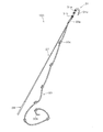
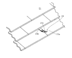
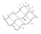
図1は本発明に係る屋根作業用安全棒の斜視図、図2はスレート葺き屋根に設けられた屋根作業用安全具の斜視図、図3は瓦葺き屋根に設けられた屋根作業用安全具の斜視図である。
Hereinafter, preferred embodiments of a safety rod for roof work according to the present invention will be described in detail with reference to the drawings.
1 is a perspective view of a safety rod for roof work according to the present invention, FIG. 2 is a perspective view of a safety tool for roof work provided on a slate thatched roof, and FIG. 3 is a perspective view of a safety tool for roof work provided on a tiled roof. It is a perspective view.
屋根作業用安全棒100は、図2,図3に示す傾斜屋根面21に固定され環状の安全索係止部23a,25bを有する屋根作業用安全具23,25に引っ掛けて使用される。
図2に示す安全具23は、ステンレスなどの耐錆性のある所定厚みの金属板をプレス成形などによって一体成型した、全体として長板形状のものであり、取付部23bが屋根下地材に固定される。また、係止部23aの中央には、安全索(命綱)先端のカラビナなどの係止具を掛止するための係止孔23cがプレス打抜きなどによって開口されている。
The roof
The
一方、図3に示す安全具25は、ステンレスなどの耐錆性のある所定厚みの金属板をプレス成形などによって一体成型した図示しない取付部を備え、この取付部が屋根下地材に固定される。また、取付部にはワイヤ25aの基端が締結され、ワイヤ25aの先端は中途部にカシメられてループ状の係止部25bを形成している。なお、図2,図3に示した板状安全具23,ワイヤ状安全具25は例示であり、安全棒100の使用対象となる安全具はこれらの構成のものに限定されるものではなく、少なくとも環状の係止部を備えるものであればよい。
On the other hand, the
図1に示すように、安全棒100は、棒本体27と、グリップ部29と、フック部31と、親綱33とを主要部材として有している。
棒本体27は、軽量で高強度を有し、しなやかな素材とするものであることが好ましく、例えば木(竹等)製、グラスファイバー製、中空のカーボンロッド製などとすることができる。棒本体27は、安全棒100の全長が例えば1550mm程度であるので、それよりも若干短い寸法となる。なお、軽量化を図るため、棒本体27は、先端に向かって徐々に縮径した先細り形状であってもよい。
As shown in FIG. 1, the
The
棒本体27の一端にはグリップ部29が設けられる。グリップ部29は、棒本体27に、ゴム、スポンジ等からなる滑り止めチューブを外挿して固着するものであってもよい。この他、棒本体27に複数の滑り止め溝を形成したり、紐等を巻回することによって滑り止め部を形成するものであってもよい。
A
棒本体27の先端となる他端には鉤状のフック部31が設けられ、フック部31は上記した安全具23の係止部23a又は安全具25の係止部25bに引っ掛け可能となっている。フック部31は、フック本体部31aが棒本体27の他端に固定される。フック本体部31aの基端には後述の親綱33が締結される環部31bが形成される。フック本体部31aの先端31cは、先細りに形成され、かつ棒本体27の一端側へU字状に曲げられて、上記の安全具23の係止部23a又は安全具25の係止部25bに引っ掛け可能となる。
A hook-
このフック部31は、例えば、フック本体部31a、環部31b、先端31cをアルミ一体成形によって作製することができる。この他、樹脂成形や鍛造によって作製されるものであってもよい。
For example, the
フック部31の環部31bには親綱33の始端33aが締結され、親綱33の終端33bは自由端となる。親綱33の全長は、上記した安全棒100の全長に対して例えば2000mm程度とすることができる。なお、安全棒100は、これら全ての構成部材を組付けた総重量が、750g程度以下であることが、片手による作業性の面から好適となる。
The
親綱33には複数のこぶ部33cが設けられている。こぶ部33cは、親綱33を環状に曲げて形成したループ部に、終端33bを通して結ぶことで形成される。これが複数回繰り替えされることで、親綱33の所定間隔に複数のこぶ部33cが設けられている。このこぶ部33c同士の間隔は、例えば300mm程度とすることができる。このようなこぶ部33cによれば、他の部材を用いず、親綱33のみを用いて確実な滑り止めを複数設けることができ、製造コストを増大させずに、安全性を向上させることができる。
The
次に、上記の屋根作業用安全棒100の作用を説明する。
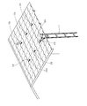
図4は傾斜屋根面への梯子の固定状況を表した斜視図である。
傾斜屋根面21上で作業を行うには、先ず、梯子41が軒先に立てかけられる。梯子41を昇った作業者は、傾斜屋根面21の最下部にある例えば安全具25に、梯子固定ロープ43を係止する。
作業者は、その後、梯子41の上部から傾斜屋根面21へ昇り上がる。このとき、傾斜屋根面21上の最も近い安全具25の係止部25bに命綱を係止するか、或いは、安全棒100を用い、すなわち、梯子41上から安全棒100を屋根面21の中程に位置する安全具25にフック部31を引っ掛け、その親綱33を伝って昇り上がる。そして、屋根面21へ上がった作業者は、フック部31の引っ掛かっている安全具25の係止部25aに命綱45を係止する。なお、この命綱45は、図5に示すように、作業者47の腰に締めた専用バンド49に基端が固定されている。
Next, the operation of the roof
FIG. 4 is a perspective view showing how the ladder is fixed to the inclined roof surface.
In order to work on the
Thereafter, the worker ascends from the upper portion of the
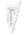
図5は屋根作業用安全棒を用いて他の安全索係止部へ移動する際の状況を表した説明図である。なお、図5においては図4と異なる安全具23を例示(図示)するがその作用は安全具25の場合と同様である。
安全具23の係止部23aが所定間隔で設けられた傾斜屋根面21での作業中に、作業者47が例えば他の作業場所へ移動するため、現在命綱45を係止している図5中右側の係止部23aから、図5中左側の他の係止部23aへ命綱45の掛け替えを行う際には、先ず、グリップ部29が把持され、棒本体27のフック部31が他の係止部23aに引っ掛けられる。
FIG. 5 is an explanatory view showing a situation when moving to another safety rope locking portion using a roof work safety rod. In FIG. 5, a
FIG. 5 shows that the
作業者47は、当該フック部31に締結される親綱33のこぶ部33cの直上を把持するとともに、現在係止中の係止部23aから命綱45を外し、親綱33を伝って他の係止部23aの位置まで移動する。
なお、この際、棒本体27は、フック部31を係止するためのものであり、登坂用の支持のためには使用しない。
次いで、他の係止部23aへ命綱45を係止した後、安全棒100のフック部31を外す。これにより、命綱45を係止する前の他の係止部23aから予め支持をとることが可能となる。
The
At this time, the rod
Next, after the
したがって、上記の屋根作業用安全棒100によれば、係止部23aに引っ掛け可能となった鉤状のフック部31を棒本体27の他端に設け、終端33bが自由端となる親綱33の始端33aをこのフック部31に締結したので、係止部23aが所定間隔で設けられた傾斜屋根面21での作業中に、例えば作業者47が現在命綱を係止している係止部23aから、他の係止部23aへ命綱45の掛け替えを行う際に、他の係止部23aにフック部31を引っ掛け、当該フック部31に締結される親綱33を把持することで、予め他の係止部23aから支持をとることができる。この結果、命綱45を現在係止中の係止部23aから外して他の係止部23aへ掛け替えるまでの間の命綱未係止状態における安全性を確保することができる。
Therefore, according to the roof
また、屋根上から地上に降りる際には、上記と逆の手順にて親綱33を伝うことで、作業者47は移動し、梯子41にて降りる。
Further, when descending from the roof to the ground, the
なお、この安全棒100は、掛止部23aにフック部31が引っ掛かったままで放置されれば、作業中に屋根より落下させてしまうことがないが、落下防止紐などを安全棒100に取り付けて、作業者47の身体の一部に連結させることとすれば、不用意に落下させることがなくなる。
The
21…傾斜屋根面
23,25…屋根作業用安全具
23a,25b…環状の安全索係止部
27…棒本体
29…グリップ部
31…フック部
31c…先端
33…親綱
33a…始端
33b…終端
33c…こぶ部
100…屋根作業用安全棒
DESCRIPTION OF
Claims (2)
棒本体と、
該棒本体の一端に設けられるグリップ部と、
前記棒本体の他端に設けられ先端が該棒本体の一端側へ曲げられて前記安全索係止部に引っ掛け可能となった鉤状のフック部と、
該フック部に始端が締結固定されるとともに終端が自由端となる親綱と、
を具備したことを特徴とする屋根作業用安全棒。 A safety rod for roof work that is used by being hooked on a safety tool for roof work that is fixed to an inclined roof surface and has an annular safety rope locking portion,
A rod body;
A grip portion provided at one end of the rod body;
A hook-shaped hook portion provided at the other end of the rod main body, the tip of which is bent toward one end of the rod main body and can be hooked on the safety rope locking portion;
A master rope whose start end is fastened and fixed to the hook portion and whose end is a free end;
A safety rod for roof work characterized by comprising:
Priority Applications (1)
| Application Number | Priority Date | Filing Date | Title |
|---|---|---|---|
| JP2004113195A JP2005299112A (en) | 2004-04-07 | 2004-04-07 | Safety rod for roof work |
Applications Claiming Priority (1)
| Application Number | Priority Date | Filing Date | Title |
|---|---|---|---|
| JP2004113195A JP2005299112A (en) | 2004-04-07 | 2004-04-07 | Safety rod for roof work |
Publications (1)
| Publication Number | Publication Date |
|---|---|
| JP2005299112A true JP2005299112A (en) | 2005-10-27 |
Family
ID=35330996
Family Applications (1)
| Application Number | Title | Priority Date | Filing Date |
|---|---|---|---|
| JP2004113195A Pending JP2005299112A (en) | 2004-04-07 | 2004-04-07 | Safety rod for roof work |
Country Status (1)
| Country | Link |
|---|---|
| JP (1) | JP2005299112A (en) |
Cited By (5)
| Publication number | Priority date | Publication date | Assignee | Title |
|---|---|---|---|---|
| JP2011174301A (en) * | 2010-02-25 | 2011-09-08 | Professional School For Photovoltaic Installation | Method for ensuring safety of work on roof and mounting tool for safety measures used therefor |
| JP2012007367A (en) * | 2010-06-24 | 2012-01-12 | Toshiba Corp | Separate type ladder |
| JP2016008434A (en) * | 2014-06-25 | 2016-01-18 | トヨタホーム株式会社 | Master rope installation method and parent rope installation control rod |
| JP2019084059A (en) * | 2017-11-07 | 2019-06-06 | ケイミュー株式会社 | Main rope holding tool and main rope installation method |
| JP2021165929A (en) * | 2020-04-07 | 2021-10-14 | トヨタホーム株式会社 | Design support system |
-
2004
- 2004-04-07 JP JP2004113195A patent/JP2005299112A/en active Pending
Cited By (7)
| Publication number | Priority date | Publication date | Assignee | Title |
|---|---|---|---|---|
| JP2011174301A (en) * | 2010-02-25 | 2011-09-08 | Professional School For Photovoltaic Installation | Method for ensuring safety of work on roof and mounting tool for safety measures used therefor |
| JP2012007367A (en) * | 2010-06-24 | 2012-01-12 | Toshiba Corp | Separate type ladder |
| JP2016008434A (en) * | 2014-06-25 | 2016-01-18 | トヨタホーム株式会社 | Master rope installation method and parent rope installation control rod |
| JP2019084059A (en) * | 2017-11-07 | 2019-06-06 | ケイミュー株式会社 | Main rope holding tool and main rope installation method |
| JP7021909B2 (en) | 2017-11-07 | 2022-02-17 | ケイミュー株式会社 | Master rope holder and master rope installation method |
| JP2021165929A (en) * | 2020-04-07 | 2021-10-14 | トヨタホーム株式会社 | Design support system |
| JP7426887B2 (en) | 2020-04-07 | 2024-02-02 | トヨタホーム株式会社 | Design support system |
Similar Documents
| Publication | Publication Date | Title |
|---|---|---|
| US5143170A (en) | Safety device for roof work | |
| US5636704A (en) | Ascender for a roofing safety system | |
| US5248021A (en) | Fall arrest lifeline roof anchor | |
| US9988842B2 (en) | Ladders including rope and pulley system and fall protection device | |
| US10760338B2 (en) | Ladder securing apparatuses, ladders incorporating same and related methods | |
| US10071268B2 (en) | Roof-mounted fall-arrest safety device | |
| US2708543A (en) | Rubber grip roof ladder | |
| CN104563849A (en) | ladder docking device | |
| US5975239A (en) | Anchor for a roofing safety system | |
| US20060059844A1 (en) | Roof anchor | |
| KR102814965B1 (en) | Rope holding apparatus for preventing fall of high place worker | |
| US20170356245A1 (en) | Roof mounted ladder safety bracket | |
| US10569110B2 (en) | Outrigger-equipped roof-mounted fall-arrest safety device | |
| US20070278040A1 (en) | Ladder securing plate | |
| US20190078339A1 (en) | Adjustable roofing scaffold system and method of use | |
| JP3130466U (en) | Safety rod for roof work | |
| JP2005139813A (en) | Roof work method and equipment used for roof work | |
| JP4524434B2 (en) | Columnar lifting tool | |
| JP3842789B2 (en) | Roofing safety equipment and safety structure | |
| JP2006102219A (en) | Safety device for work on roof | |
| EP2673051B1 (en) | Safety system for a slanted roof | |
| JP2004324404A (en) | Guidance device for safety cable for building construction and mounting structure of safety cable using the same | |
| JP2952165B2 (en) | Operation rod of hanging bracket for safety net | |
| US20250256137A1 (en) | Reach remote elevated anchor | |
| KR100817206B1 (en) | elevator |