JP2005299101A - Concrete member joint structure - Google Patents
Concrete member joint structure Download PDFInfo
- Publication number
- JP2005299101A JP2005299101A JP2004112757A JP2004112757A JP2005299101A JP 2005299101 A JP2005299101 A JP 2005299101A JP 2004112757 A JP2004112757 A JP 2004112757A JP 2004112757 A JP2004112757 A JP 2004112757A JP 2005299101 A JP2005299101 A JP 2005299101A
- Authority
- JP
- Japan
- Prior art keywords
- concrete
- concrete member
- joint
- section
- main
- Prior art date
- Legal status (The legal status is an assumption and is not a legal conclusion. Google has not performed a legal analysis and makes no representation as to the accuracy of the status listed.)
- Granted
Links
Images

Landscapes
- Rod-Shaped Construction Members (AREA)
- Reinforcement Elements For Buildings (AREA)
Abstract
【課題】 互いに接合される二つのコンクリート部材の接合部において、一方のコンクリート部材のひび割れや圧壊等の被害を抑制すると共に、曲げモーメント及びせん断力に対する耐力の低下を抑制し、コンクリートが負担するせん断力を低減する。
【解決手段】 互いに接合される二つのコンクリート部材A、Bの内、一方のコンクリート部材A中に材軸方向に配筋される主筋1と、他方のコンクリート部材B中に定着されながら一方のコンクリート部材Aまで延長させられ、一方のコンクリート部材A中で各主筋1に沿い、一方のコンクリート部材A中に配筋される接合部筋2を用い、主筋1を少なくとも他方のコンクリート部材Bとの境界面まで配筋し、接合部筋2を一方のコンクリート部材A中で部材成中央部に向けて斜めに配筋し、他方のコンクリート部材Bより遠い区間でコンクリートに付着させ、他方のコンクリート部材B寄りの区間でコンクリートに付着させない。
【選択図】 図1
PROBLEM TO BE SOLVED: To suppress the damage such as cracking or crushing of one concrete member at a joint portion between two concrete members to be joined to each other, and to suppress a decrease in a yield strength against a bending moment and a shearing force, and a shear that concrete bears. Reduce power.
Among two concrete members A and B to be joined together, a main reinforcement 1 arranged in the direction of the material axis in one concrete member A and one concrete while being fixed in the other concrete member B The joint bars 2 are extended to the member A, along the main bars 1 in the one concrete member A, and arranged in the one concrete member A, and the main bar 1 is bound to at least the other concrete member B. The bar is arranged to the surface, the joint bar 2 is diagonally arranged toward the center of the component in one concrete member A, and is attached to the concrete in a section farther from the other concrete member B, and the other concrete member B Do not adhere to concrete in the close section.
[Selection] Figure 1
Description
この発明は互いに接合される二つのコンクリート部材の接合部において、一方のコンクリート部材のコンクリートのひび割れや圧壊、鉄筋の座屈等の被害を抑制するコンクリート部材の接合部構造に関するものである。 The present invention relates to a joint structure for a concrete member that suppresses damage such as cracking and crushing of concrete in one concrete member and buckling of a reinforcing bar in a joint portion between two concrete members to be joined together.
例えば鉄筋コンクリート造の柱部材と梁部材との接合部において、大地震時に梁主筋が降伏した後のコンクリートのひび割れや圧壊等の被害を抑制する方法として、梁主筋の一部の区間をコンクリートから絶縁させることにより梁主筋の伸び変形能力を高めると共に、コンクリートとの付着による付着割裂破壊を防止する方法がある(特許文献1、特許文献2参照)。
このように梁主筋の柱部材寄りの一部の区間の、コンクリートとの付着を切ることは梁端部におけるヒンジ形成後の梁部材の破壊を防止することを可能にするものの、梁部材自体の曲げモーメント及びせん断力に対する抵抗力を減少させることになるため、梁部材のヒンジ形成部分はもはやヒンジを生じていない部分と同等の耐力を維持することができない。 As described above, cutting the adhesion of the section of the beam reinforcement near the column member to the concrete can prevent the beam member from being destroyed after the hinge is formed at the beam end, but the beam member itself Since the resistance to bending moments and shear forces is reduced, the hinged portion of the beam member can no longer maintain the same proof strength as the portion that is not hinged.
この発明は上記背景より、ヒンジ形成部分の曲げモーメント及びせん断力に対する耐力の低下とコンクリートの損傷を抑制する接合部構造を提案するものである。 In view of the above background, the present invention proposes a joint structure that suppresses a decrease in yield strength against bending moment and shearing force of a hinge forming portion and damage to concrete.
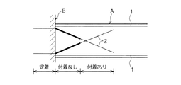
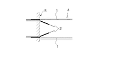
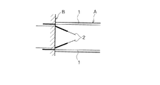
本発明では図1、図3に示すように互いに接合される二つのコンクリート部材A、Bの内、一方のコンクリート部材A中に材軸方向に配筋される主筋1と、他方のコンクリート部材B中に定着されながら、一方のコンクリート部材Aまで延長させられて配筋される接合部筋2を用い、主筋1を少なくとも他方のコンクリート部材Aとの境界面まで配筋し、接合部筋2を一方のコンクリート部材A中でその部材成の中央部に向けて斜めに配筋され、他方のコンクリート部材より遠い区間においてコンクリートに付着させ、他方のコンクリート部材寄りの区間においてコンクリートに付着させないことにより、コンクリート部材Aのひび割れや圧壊等の被害を抑制すると共に、曲げモーメント及びせん断力に対する耐力の低下を抑制し、併せてコンクリートが負担するせん断力を低減する。
In the present invention, as shown in FIG. 1 and FIG. 3, the main reinforcing
図面では接合部筋2の内の太線で示す部分がコンクリートとの付着が切れた区間(付着なしの区間)を示す。接合部筋2をコンクリートに付着させない(接合部筋2の付着を切る)状態は接合部筋2にグリースを塗る、布やスリーブを被せる等により得られるが、方法は問われない。
In the drawing, a portion indicated by a thick line in the
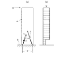
例えば図2−(a)のように片持ち梁状態の一方のコンクリート部材Aに材軸に直交する方向の荷重(せん断力)が作用したとき、一方のコンクリート部材Aは荷重の作用方向に変形しようとし、引張側の接合部筋2が引張力を負担する。
For example, when a load (shearing force) in a direction perpendicular to the material axis is applied to one concrete member A in a cantilever state as shown in FIG. 2- (a), one concrete member A is deformed in the direction in which the load is applied. Attempt is made and the
このとき、接合部筋2が他方のコンクリート部材B中に定着されながら、一方のコンクリート部材A中では他方のコンクリート部材より遠い区間においてコンクリートに付着し、他方のコンクリート部材B寄りの区間においてコンクリートに付着しないことで、引張側の接合部筋2はコンクリートとの付着がある区間(付着ありの区間)において一方のコンクリート部材Aの変形に追従し、付着がない区間において伸び変形を生じ、降伏に至る。降伏時のコンクリート部材の変形は付着がない区間の長さを調整することにより自由に設定される。
At this time, while the
接合部筋2が付着なしの区間において伸び変形を生ずることで、接合部筋2が一方のコンクリート部材A中で完全に付着している場合との対比では、付着を切った区間では接合部筋2が負担する引張力及び圧縮力によって接合部筋2を除くコンクリート部材Aにおけるせん断力及び曲げモーメントが付着のある場合に比べて低減されるため、せん断力及び曲げモーメントによるコンクリートの損傷が低減される。
In contrast to the case where the
併せて接合部筋2が一方のコンクリート部材A中で交差部分寄りの区間においてコンクリートに付着し、他方のコンクリート部材B寄りの区間においてコンクリートに付着しないことで、図2−(a)に示すように付着した区間にせん断力に対する反力が生じ、その反力の、材軸に直交する方向の成分がせん断力に抵抗するため、図2−(b)のように一方のコンクリート部材Aの、接合部筋2を除く部分に作用するせん断力も低減され、一方のコンクリート部材Aの端部におけるコンクリートのせん断破壊が抑制される。
In addition, as shown in FIG. 2- (a), the
また図2−(a)に示す、接合部筋2の付着区間における反力の材軸方向の成分は前記せん断力による曲げモーメントに対する曲げ戻しの偶力を形成するため、せん断力による曲げモーメントを低減し、一方のコンクリート部材Aのヒンジ部におけるコンクリートの損傷を軽減する効果を発揮する。曲げ戻しによる曲げモーメントの低減効果から、一方のコンクリート部材Aの端部におけるひび割れと圧壊が抑制されることが分かる。
In addition, the component in the material axis direction of the reaction force in the attachment section of the
加えて例えば特許文献2の図12のように、特許文献2の梁主筋7に相当する主筋1が特許文献2の梁主筋5に相当する接合部筋2の付着ありの区間までにしか配筋されずに、接合部筋2の、他方のコンクリート部材B寄りの区間におけるコンクリートとの付着が切られれば、接合部筋2の付着なしの区間には一体化した鉄筋コンクリート造の主筋に相当する鉄筋が不在の状態になり、付着なしの区間においてはコンクリートのみで抵抗することになるため、一方のコンクリート部材Aの曲げモーメント及びせん断力に対する抵抗力が低下する。
In addition, for example, as shown in FIG. 12 of
これに対し、本発明では一方のコンクリート部材Aの主筋1が少なくとも他方のコンクリート部材Bとの境界面まで配筋され、その境界面まで主筋1がその周囲のコンクリートに付着していることで、一方のコンクリート部材A中で接合部筋2の付着を切った区間(付着なしの区間)にコンクリートと一体となった主筋1が存在しているため、一方のコンクリート部材Aのヒンジ形成部分にヒンジを形成しない部分と同様の曲げモーメント及びせん断力に対する抵抗力を持たせることが可能になる。
On the other hand, in the present invention, the
すなわち、接合部筋2の付着なしの区間では主筋1とその周囲のコンクリートとが両者間の付着力によって一体化しているため、主筋1とコンクリート間でヒンジを形成しない部分と同様の応力を付着力により伝達することができる。
That is, in the section where the
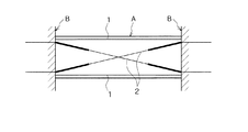
接合部筋2は図1に示すように一方のコンクリート部材Aの、他方のコンクリート部材B寄りの端部にのみ部分的に配筋される場合と、図3に示すように全長に亘って配筋される場合(請求項2)があり、両コンクリート部材A、Bの部位に応じて使い分けられる。後者の場合、接合部筋2は一方のコンクリート部材Aの材軸方向中央部で互いに交差する。
As shown in FIG. 1, the
本発明の一方のコンクリート部材Aの主筋1は少なくとも他方のコンクリート部材Bとの境界面まで配筋されればよいため、図1に示すようにコンクリート部材A、Bの部位によって他方のコンクリート部材Bとの境界面で留まる場合と、図4に示すように他方のコンクリート部材Bの内部まで延長させられて配筋される場合(請求項3)がある。
Since the
一方のコンクリート部材Aの主筋1を他方のコンクリート部材Bの内部まで配筋する請求項3によれば、境界面で留まる場合よりヒンジ部の損傷は増すものの、主筋1に作用する引張力の負担能力が増大するため、一方のコンクリート部材Aの曲げモーメントに対する抵抗力が増大することになる。
According to claim 3 in which the
主筋1が他方のコンクリート部材Bの内部まで配筋される請求項3では、図4に示すように主筋1を他方のコンクリート部材Bの内部においてコンクリートに完全に付着させる場合と、ヒンジ部の損傷を減じるために、図5に示すように他方のコンクリート部材Bの内部で一方のコンクリート部材A寄りの一部の区間をコンクリートに付着させない場合がある(請求項4)。図6は請求項4の特殊な場合として主筋1の、他方のコンクリート部材Bの内部における全区間のコンクリートとの付着を切った場合(請求項5)を示す。図7は接合部筋2が一方のコンクリート部材Aの全長に亘って配筋される場合(請求項2)を示す。
In claim 3 where the main reinforcing
主筋1の、他方のコンクリート部材Bの内部における少なくとも一方のコンクリート部材A寄りの一部の区間の付着を切る請求項4によれば、その付着を切った区間において主筋1が降伏することができるため、コンクリート部材Aが損傷をほとんど受けずに変形することが可能である。
According to the fourth aspect of the present invention, the
特に請求項5に記載のように主筋1の、他方のコンクリート部材Bの内部における全区間のコンクリートとの付着を切れば、主筋1の、他方のコンクリート部材Bの内部における全区間が伸び変形することがなく、引張応力も生じないため、一方のコンクリート部材Aの材軸に直交する方向のせん断力に対し、主筋1が他方のコンクリート部材Bに伝達する機能(ダボ作用)を十分に発揮することができる。
In particular, as described in claim 5, if the
他方のコンクリート部材中に定着されながら、一方のコンクリート部材まで延長させられて配筋される接合部筋を一方のコンクリート部材中でその部材成の中央部に向けて斜めに配筋し、他方のコンクリート部材より遠い区間においてコンクリートに付着させ、他方のコンクリート部材寄りの区間においてコンクリートに付着させないことで、一方のコンクリート部材に材軸に直交する方向の荷重(せん断力)に対し、接合部筋のコンクリートとの付着がない区間に伸び変形を生じさせることができ、接合部筋が完全に付着している場合より大きい引張力を負担させることができるため、一方のコンクリート部材の、接合部筋を除くコンクリートが負担すべき引張応力を低減し、それに伴うひび割れを抑制することができる。 While being fixed in the other concrete member, the joint bar which is extended to one concrete member and arranged is diagonally arranged toward the center of the member in one concrete member, and the other By adhering to the concrete in the section far from the concrete member and not adhering to the concrete in the section close to the other concrete member, the load of the joint muscle of one concrete member against the load (shearing force) in the direction perpendicular to the material axis It is possible to cause elongation deformation in a section where there is no adhesion with concrete, and it is possible to bear a greater tensile force when the joint reinforcement is completely attached. It is possible to reduce the tensile stress that must be borne by the removed concrete and to suppress the cracks associated therewith.
また接合部筋が他方のコンクリート部材中に定着されながら、一方のコンクリート部材中では他方のコンクリート部材より遠い区間においてコンクリートに付着し、他方のコンクリート部材寄りの区間においてコンクリートに付着しないことで、付着した区間にせん断力に対する反力が生じ、その反力の、材軸に直交する方向の成分がせん断力に抵抗するため、一方のコンクリート部材の、接合部筋を除く部分に作用するせん断力も低減し、一方のコンクリート部材の端部におけるコンクリートのせん断破壊を防止することができる。 In addition, while the joint line is fixed in the other concrete member, it adheres to the concrete in one concrete member in the section far from the other concrete member, and does not adhere to the concrete in the section near the other concrete member. A reaction force against the shearing force is generated in the section, and the component of the reaction force in the direction perpendicular to the material axis resists the shearing force, so the shearing force acting on the part of one concrete member excluding the joint is also reduced. In addition, it is possible to prevent the shear failure of the concrete at the end of one concrete member.
この接合部筋の付着区間における反力の材軸方向の成分はせん断力による曲げモーメントに対する曲げ戻しの偶力を形成するため、せん断力による曲げモーメントを低減し、一方のコンクリート部材のヒンジ部におけるコンクリートの損傷を軽減する効果も発揮する。 The component in the material axis direction of the reaction force in the bonded section of the joint line forms a couple of bending back to the bending moment due to the shearing force, thus reducing the bending moment due to the shearing force and at the hinge part of one concrete member It also has the effect of reducing concrete damage.
加えて一方のコンクリート部材の主筋が少なくとも他方のコンクリート部材との境界面まで配筋され、その境界面まで主筋がその周囲のコンクリートに付着していることで、接合部筋の、一方のコンクリート部材中の付着を切った区間にコンクリートと一体となった主筋が存在するため、一方のコンクリート部材のヒンジ形成部分にヒンジを形成しない部分と同様の曲げモーメント及びせん断力に対する抵抗力を持たせることが可能であり、この接合部筋の付着なしの区間では主筋とコンクリート間でヒンジを形成しない部分と同様の応力を付着力により伝達することができる。 In addition, the main reinforcement of one concrete member is arranged to at least the boundary surface with the other concrete member, and the main reinforcement adheres to the surrounding concrete up to the boundary surface, so that one concrete member of the joint reinforcement Since there is a main reinforcement united with concrete in the section where the adhesion is cut, the hinge forming part of one concrete member can have the same resistance to bending moment and shear force as the part that does not form the hinge. It is possible, and in the section where the joint bars do not adhere, the same stress as that of the portion where the hinge is not formed between the main bars and the concrete can be transmitted by the adhesive force.
請求項3では一方のコンクリート部材の主筋を他方のコンクリート部材の内部まで配筋することで、境界面で留まる場合より主筋に作用する引張力の負担能力が増大するため、一方のコンクリート部材の曲げモーメントに対する抵抗力を増大させることができる。 In claim 3, by placing the main reinforcement of one concrete member to the inside of the other concrete member, the load capacity of the tensile force acting on the main reinforcement is increased as compared with the case of staying at the boundary surface. The resistance to the moment can be increased.
請求項4では主筋の、他方のコンクリート部材の内部における少なくとも一方のコンクリート部材寄りの一部の区間をコンクリートに付着させないことで、付着を切った区間において主筋が降伏することができるため、コンクリート部材が損傷をほとんど受けずに変形することが可能であり、他方のコンクリート部材のヒンジ部の損傷を減じることができる。 In claim 4, the main bar can yield in the section where the adhesion is cut by not attaching the part of the main bar close to at least one concrete member inside the other concrete member, so that the main bar can yield. Can be deformed with little damage, and damage to the hinge portion of the other concrete member can be reduced.
請求項5では主筋の、他方のコンクリート部材の内部における全区間のコンクリートとの付着を切ることで、主筋の、他方のコンクリート部材の内部における全区間が伸び変形することがなく、引張応力も生じないため、主筋の、一方のコンクリート部材Aの内部における区間に引張力を作用させることなく、一方のコンクリート部材Aの材軸に直交する方向のせん断力を他方のコンクリート部材に伝達する機能(ダボ作用)を発揮させることができる。 According to claim 5, the main reinforcing bar is not attached to the whole concrete section inside the other concrete member, so that the whole main reinforcing bar section inside the other concrete member is not stretched and deformed, and tensile stress is also generated. Therefore, the function of transmitting the shearing force in the direction perpendicular to the material axis of one concrete member A to the other concrete member without applying a tensile force to the section inside the one concrete member A of the main reinforcement (the dowel) Action).
この発明は図1、図3に示すように互いに接合される二つのコンクリート部材A,Bの内、一方のコンクリート部材A中に材軸方向に配筋される主筋1と、他方のコンクリート部材B中に定着されながら、一方のコンクリート部材Aまで延長させられ、その一方のコンクリート部材A中で各主筋1に沿い、一方のコンクリート部材Aに配筋される接合部筋2を用い、二つのコンクリート部材A,Bを接合して構成される接合部構造である。主筋1は主に一方のコンクリート部材A中にその成方向、または幅方向に対になって配筋され、接合部筋2は主に一方のコンクリート部材Aの成方向、または幅方向に対になって配筋される。
As shown in FIG. 1 and FIG. 3, the present invention includes a
主筋1は少なくとも他方のコンクリート部材Bとの境界面まで配筋され、接合部筋2は一方のコンクリート部材A中でその部材成の中央部に向けて斜めに配筋され、他方のコンクリート部材Bより遠い区間においてコンクリートに付着し、他方のコンクリート部材B寄りの区間においてコンクリートに付着しない。
The
図1、図3はコンクリート部材Aが梁、コンクリート部材Bが柱、または耐力壁である場合に、コンクリート部材A中に配筋された主筋1をコンクリート部材Bとの境界面で止めた場合を示す。図1は接合部筋2をコンクリート部材Aの端部にのみ配筋した場合であり、図3は接合部筋2をコンクリート部材Aの全長に亘って配筋した場合(請求項2)である。いずれの場合も接合部筋2はコンクリート部材A内の区間で互いに交差するが、必ずしも図示するようにコンクリート部材A内の区間における中央部で交差する必要はない。
1 and 3 show a case where the
コンクリート部材A、Bは柱と梁、耐力壁と柱又は梁、上階の柱と下階の柱、柱と基礎、杭と基礎(フーチング)の他、耐力壁と耐力壁、フラットスラブのようなスラブと柱等、互いに接合されるコンクリート部材であれば部位を問わない。また現場打ちコンクリート造であるかプレキャストコンクリート製であるかも問わず、鉄筋コンクリート造、鉄骨鉄筋コンクリート造、鋼管コンクリート造(CFT)、またはいずれかの組み合わせの場合の他、プレストレスを与える場合もある。 Concrete members A and B include columns and beams, bearing walls and columns or beams, upper-floor columns and lower-floor columns, columns and foundations, piles and foundations (footings), bearing walls and bearing walls, and flat slabs. Any part may be used as long as it is a concrete member joined to each other such as a slab and a pillar. It may be precast concrete, whether it is made of cast-in-place concrete or precast concrete, and may be prestressed in addition to reinforced concrete, steel reinforced concrete, steel pipe concrete (CFT), or any combination thereof.
図4〜図7は主筋1をコンクリート部材Bとの境界面を超え、コンクリート部材Bの内部まで配筋した場合(請求項3)を示す。図4は主筋1のコンクリート部材B内の区間をそのコンクリート中に定着させた場合、図5は主筋1の、コンクリート部材B内のコンクリート部材A寄りの区間の付着を切った場合(請求項4)である。図6、図7は主筋1のコンクリート部材B内の全区間に亘り、コンクリートとの付着を切った場合(請求項5)である。図6、図7はコンクリート部材Aが梁の場合を示しているが、コンクリート部材Aを柱に、コンクリート部材Bを基礎やスラブに置き換えることもできる。
4 to 7 show a case where the main reinforcing
図6、図7の場合、主筋1のコンクリート部材B内の全区間の付着を切ることで、コンクリート部材B内の区間にコンクリート部材Aの材軸に直交する方向のせん断力に対しては、コンクリート部材B内で付着を切った区間が伸び変形せず、降伏もしないため、主筋1の、コンクリート部材Aの内部における区間に引張力を作用させることがない。また主筋1のコンクリート部材B内で付着を切った区間は常に健全に保たれるため、コンクリート部材Aからのせん断力をコンクリート部材Bに伝達する良好な機能(ダボ作用)を発揮する。
In the case of FIG. 6 and FIG. 7, by cutting the adhesion of the entire section in the concrete member B of the
A……一方のコンクリート部材、B……他方のコンクリート部材、
1……主筋、2……接合部筋
A: One concrete member, B: The other concrete member,
1 …… Main muscle, 2 …… Juncture muscle
Claims (5)
The joint structure of a concrete member according to claim 4, wherein the entire section of the main reinforcement inside the other concrete member does not adhere to the concrete.
Priority Applications (1)
| Application Number | Priority Date | Filing Date | Title |
|---|---|---|---|
| JP2004112757A JP4642373B2 (en) | 2004-04-07 | 2004-04-07 | Concrete member joint structure |
Applications Claiming Priority (1)
| Application Number | Priority Date | Filing Date | Title |
|---|---|---|---|
| JP2004112757A JP4642373B2 (en) | 2004-04-07 | 2004-04-07 | Concrete member joint structure |
Publications (2)
| Publication Number | Publication Date |
|---|---|
| JP2005299101A true JP2005299101A (en) | 2005-10-27 |
| JP4642373B2 JP4642373B2 (en) | 2011-03-02 |
Family
ID=35330986
Family Applications (1)
| Application Number | Title | Priority Date | Filing Date |
|---|---|---|---|
| JP2004112757A Expired - Lifetime JP4642373B2 (en) | 2004-04-07 | 2004-04-07 | Concrete member joint structure |
Country Status (1)
| Country | Link |
|---|---|
| JP (1) | JP4642373B2 (en) |
Cited By (3)
| Publication number | Priority date | Publication date | Assignee | Title |
|---|---|---|---|---|
| KR101266215B1 (en) * | 2011-02-23 | 2013-05-21 | 성균관대학교산학협력단 | Improved seismic performance of Staggered wall system with central hall |
| US9419308B2 (en) | 2007-03-29 | 2016-08-16 | Tdk Corporation | All-solid-state lithium-ion secondary battery and production method thereof |
| JP2023009704A (en) * | 2021-07-07 | 2023-01-20 | 大成建設株式会社 | Beam member and joint structure between beam member and vertical member |
Citations (6)
| Publication number | Priority date | Publication date | Assignee | Title |
|---|---|---|---|---|
| JPH055342A (en) * | 1991-06-27 | 1993-01-14 | Hazama Gumi Ltd | Structure for arrangement of beam main reinforcement |
| JP2000110356A (en) * | 1998-10-01 | 2000-04-18 | Kumagai Gumi Co Ltd | Method for securing fixed length of beam main reinforcement |
| JP2001012010A (en) * | 1999-06-29 | 2001-01-16 | Maeda Corp | Construction of reinforced concrete beam having x- shaped bar arrangement |
| JP2003336315A (en) * | 2002-05-23 | 2003-11-28 | Maeda Corp | Reinforced concrete beam structure |
| JP2004052494A (en) * | 2002-07-24 | 2004-02-19 | Kajima Corp | RC beam damper |
| JP2004068304A (en) * | 2002-08-02 | 2004-03-04 | Hisahiro Hiraishi | Material end fixing structure of reinforced concrete building |
-
2004
- 2004-04-07 JP JP2004112757A patent/JP4642373B2/en not_active Expired - Lifetime
Patent Citations (6)
| Publication number | Priority date | Publication date | Assignee | Title |
|---|---|---|---|---|
| JPH055342A (en) * | 1991-06-27 | 1993-01-14 | Hazama Gumi Ltd | Structure for arrangement of beam main reinforcement |
| JP2000110356A (en) * | 1998-10-01 | 2000-04-18 | Kumagai Gumi Co Ltd | Method for securing fixed length of beam main reinforcement |
| JP2001012010A (en) * | 1999-06-29 | 2001-01-16 | Maeda Corp | Construction of reinforced concrete beam having x- shaped bar arrangement |
| JP2003336315A (en) * | 2002-05-23 | 2003-11-28 | Maeda Corp | Reinforced concrete beam structure |
| JP2004052494A (en) * | 2002-07-24 | 2004-02-19 | Kajima Corp | RC beam damper |
| JP2004068304A (en) * | 2002-08-02 | 2004-03-04 | Hisahiro Hiraishi | Material end fixing structure of reinforced concrete building |
Cited By (4)
| Publication number | Priority date | Publication date | Assignee | Title |
|---|---|---|---|---|
| US9419308B2 (en) | 2007-03-29 | 2016-08-16 | Tdk Corporation | All-solid-state lithium-ion secondary battery and production method thereof |
| KR101266215B1 (en) * | 2011-02-23 | 2013-05-21 | 성균관대학교산학협력단 | Improved seismic performance of Staggered wall system with central hall |
| JP2023009704A (en) * | 2021-07-07 | 2023-01-20 | 大成建設株式会社 | Beam member and joint structure between beam member and vertical member |
| JP7713324B2 (en) | 2021-07-07 | 2025-07-25 | 大成建設株式会社 | Beam member and joint structure between beam member and vertical member |
Also Published As
| Publication number | Publication date |
|---|---|
| JP4642373B2 (en) | 2011-03-02 |
Similar Documents
| Publication | Publication Date | Title |
|---|---|---|
| JP4428304B2 (en) | Plastic hinge part of RC structure | |
| JP2001295220A (en) | High seismic performance RC pier with unbonded high strength core material | |
| JP4230533B1 (en) | Bonding structure of structure and fixing member for shear force transmission used therefor | |
| JP2002004417A (en) | Pc compression joint structure for precast concrete beam and column | |
| KR100690198B1 (en) | Steel permanent formwork beams with U-shaped connecting material and steel concrete composite beams using them | |
| JP4642373B2 (en) | Concrete member joint structure | |
| JP4989409B2 (en) | Foundation pile structure, ready-made concrete pile, and joint hardware of ready-made concrete pile and steel pipe pile | |
| JP3872769B2 (en) | Concrete member joint structure | |
| JP3741975B2 (en) | Joint structure of support pile and footing | |
| JP2005083136A (en) | Composite structure support | |
| JP4238991B2 (en) | Seismic isolation structure on the middle floor of the building | |
| JP4942475B2 (en) | Reinforcement method and structure of existing columns | |
| JP4020212B2 (en) | Hinge-induced structure of concrete members | |
| JP4819605B2 (en) | Precast prestressed concrete beams using tendons with different strength at the end and center | |
| JP3938718B2 (en) | Reinforced concrete beam structure | |
| JP3079124B2 (en) | Bridge pier reinforcement method | |
| JP4334448B2 (en) | Concrete member joint structure | |
| JP2003074117A (en) | Steel frame structure | |
| JP4224607B2 (en) | Pile hinge-induced structure | |
| JP4581729B2 (en) | Calculation method of shear stress of reinforced concrete beam, design method of reinforced concrete beam, reinforced concrete beam | |
| JP4522211B2 (en) | Joint structure of vertical member and horizontal member | |
| JP6312130B2 (en) | Column beam structure and beam end members | |
| JPH10317324A (en) | Girder bridge | |
| JP2001123462A (en) | Pile head joining structure for existing concrete pile and foundation slab concrete | |
| JP2018172893A (en) | Precast floor slab system and bridge structure |
Legal Events
| Date | Code | Title | Description |
|---|---|---|---|
| A521 | Request for written amendment filed |
Free format text: JAPANESE INTERMEDIATE CODE: A821 Effective date: 20040408 |
|
| A621 | Written request for application examination |
Free format text: JAPANESE INTERMEDIATE CODE: A621 Effective date: 20070109 |
|
| A977 | Report on retrieval |
Free format text: JAPANESE INTERMEDIATE CODE: A971007 Effective date: 20080820 |
|
| A131 | Notification of reasons for refusal |
Free format text: JAPANESE INTERMEDIATE CODE: A131 Effective date: 20100105 |
|
| A521 | Request for written amendment filed |
Free format text: JAPANESE INTERMEDIATE CODE: A523 Effective date: 20100305 |
|
| A131 | Notification of reasons for refusal |
Free format text: JAPANESE INTERMEDIATE CODE: A131 Effective date: 20100615 |
|
| A521 | Request for written amendment filed |
Free format text: JAPANESE INTERMEDIATE CODE: A523 Effective date: 20100728 |
|
| TRDD | Decision of grant or rejection written | ||
| A01 | Written decision to grant a patent or to grant a registration (utility model) |
Free format text: JAPANESE INTERMEDIATE CODE: A01 Effective date: 20101130 |
|
| A01 | Written decision to grant a patent or to grant a registration (utility model) |
Free format text: JAPANESE INTERMEDIATE CODE: A01 |
|
| A61 | First payment of annual fees (during grant procedure) |
Free format text: JAPANESE INTERMEDIATE CODE: A61 Effective date: 20101201 |
|
| R150 | Certificate of patent or registration of utility model |
Ref document number: 4642373 Country of ref document: JP Free format text: JAPANESE INTERMEDIATE CODE: R150 Free format text: JAPANESE INTERMEDIATE CODE: R150 |
|
| FPAY | Renewal fee payment (event date is renewal date of database) |
Free format text: PAYMENT UNTIL: 20131210 Year of fee payment: 3 |
|
| FPAY | Renewal fee payment (event date is renewal date of database) |
Free format text: PAYMENT UNTIL: 20131210 Year of fee payment: 3 |
|
| S531 | Written request for registration of change of domicile |
Free format text: JAPANESE INTERMEDIATE CODE: R313531 |
|
| FPAY | Renewal fee payment (event date is renewal date of database) |
Free format text: PAYMENT UNTIL: 20131210 Year of fee payment: 3 |
|
| R350 | Written notification of registration of transfer |
Free format text: JAPANESE INTERMEDIATE CODE: R350 |
|
| R250 | Receipt of annual fees |
Free format text: JAPANESE INTERMEDIATE CODE: R250 |
|
| S111 | Request for change of ownership or part of ownership |
Free format text: JAPANESE INTERMEDIATE CODE: R313117 |
|
| R250 | Receipt of annual fees |
Free format text: JAPANESE INTERMEDIATE CODE: R250 |
|
| R350 | Written notification of registration of transfer |
Free format text: JAPANESE INTERMEDIATE CODE: R350 |
|
| R250 | Receipt of annual fees |
Free format text: JAPANESE INTERMEDIATE CODE: R250 |
|
| R250 | Receipt of annual fees |
Free format text: JAPANESE INTERMEDIATE CODE: R250 |
|
| R250 | Receipt of annual fees |
Free format text: JAPANESE INTERMEDIATE CODE: R250 |
|
| R250 | Receipt of annual fees |
Free format text: JAPANESE INTERMEDIATE CODE: R250 |
|
| R250 | Receipt of annual fees |
Free format text: JAPANESE INTERMEDIATE CODE: R250 |
|
| S111 | Request for change of ownership or part of ownership |
Free format text: JAPANESE INTERMEDIATE CODE: R313117 |
|
| R350 | Written notification of registration of transfer |
Free format text: JAPANESE INTERMEDIATE CODE: R350 |
|
| R250 | Receipt of annual fees |
Free format text: JAPANESE INTERMEDIATE CODE: R250 |
|
| R250 | Receipt of annual fees |
Free format text: JAPANESE INTERMEDIATE CODE: R250 |
|
| EXPY | Cancellation because of completion of term |