JP2005298977A - Method for carburizing, quenching, and tempering steel part - Google Patents
Method for carburizing, quenching, and tempering steel part Download PDFInfo
- Publication number
- JP2005298977A JP2005298977A JP2005140283A JP2005140283A JP2005298977A JP 2005298977 A JP2005298977 A JP 2005298977A JP 2005140283 A JP2005140283 A JP 2005140283A JP 2005140283 A JP2005140283 A JP 2005140283A JP 2005298977 A JP2005298977 A JP 2005298977A
- Authority
- JP
- Japan
- Prior art keywords
- carburizing
- cap
- quenching
- steel part
- oil
- Prior art date
- Legal status (The legal status is an assumption and is not a legal conclusion. Google has not performed a legal analysis and makes no representation as to the accuracy of the status listed.)
- Pending
Links
- 238000005255 carburizing Methods 0.000 title claims abstract description 83
- 229910000831 Steel Inorganic materials 0.000 title claims abstract description 78
- 239000010959 steel Substances 0.000 title claims abstract description 78
- 238000010791 quenching Methods 0.000 title claims abstract description 68
- 230000000171 quenching effect Effects 0.000 title claims abstract description 68
- 238000000034 method Methods 0.000 title claims abstract description 51
- 238000005496 tempering Methods 0.000 title claims abstract description 34
- 238000004140 cleaning Methods 0.000 claims abstract description 12
- 230000002265 prevention Effects 0.000 claims description 43
- 238000010438 heat treatment Methods 0.000 claims description 15
- 229910000760 Hardened steel Inorganic materials 0.000 claims description 3
- 230000003449 preventive effect Effects 0.000 abstract 2
- 239000000463 material Substances 0.000 description 6
- 230000002093 peripheral effect Effects 0.000 description 6
- 239000010410 layer Substances 0.000 description 5
- 238000005192 partition Methods 0.000 description 4
- 239000007788 liquid Substances 0.000 description 3
- 238000007747 plating Methods 0.000 description 3
- 238000005406 washing Methods 0.000 description 3
- PXHVJJICTQNCMI-UHFFFAOYSA-N Nickel Chemical compound [Ni] PXHVJJICTQNCMI-UHFFFAOYSA-N 0.000 description 2
- 229910018487 Ni—Cr Inorganic materials 0.000 description 2
- 229910000975 Carbon steel Inorganic materials 0.000 description 1
- RYGMFSIKBFXOCR-UHFFFAOYSA-N Copper Chemical compound [Cu] RYGMFSIKBFXOCR-UHFFFAOYSA-N 0.000 description 1
- 230000004323 axial length Effects 0.000 description 1
- 239000010962 carbon steel Substances 0.000 description 1
- 239000003610 charcoal Substances 0.000 description 1
- 238000000576 coating method Methods 0.000 description 1
- 230000008602 contraction Effects 0.000 description 1
- 238000001816 cooling Methods 0.000 description 1
- 229910052802 copper Inorganic materials 0.000 description 1
- 239000010949 copper Substances 0.000 description 1
- 238000005520 cutting process Methods 0.000 description 1
- 230000007547 defect Effects 0.000 description 1
- 230000000694 effects Effects 0.000 description 1
- 238000000465 moulding Methods 0.000 description 1
- 229910052759 nickel Inorganic materials 0.000 description 1
- 230000008707 rearrangement Effects 0.000 description 1
- 239000002356 single layer Substances 0.000 description 1
- 239000010935 stainless steel Substances 0.000 description 1
- 229910001220 stainless steel Inorganic materials 0.000 description 1
Images

Landscapes
- Heat Treatments In General, Especially Conveying And Cooling (AREA)
- Solid-Phase Diffusion Into Metallic Material Surfaces (AREA)
Abstract
Description
本発明は、炭素鋼、Cr鋼、Cr−Mo鋼、Ni−Cr鋼、Ni−Cr−Mo鋼などの鋼製部品の浸炭焼入れ焼もどし方法に関する。 The present invention relates to a carburizing and tempering method for steel parts such as carbon steel, Cr steel, Cr—Mo steel, Ni—Cr steel, and Ni—Cr—Mo steel.
浸炭焼入れは、多数の鋼製部品(以下、ワークともいう)を格子状をなすグリッドなどのワーク保持体(保持具)に配置して浸炭処理室に入れ、浸炭性ガス雰囲気下、昇温、加熱して所定温度(浸炭温度)に保持し、そのガスを循環ないし還流させて浸炭、加熱処理する。その後、焼入液(焼入れ油)中に浸漬して急冷して所定時間保持することで焼入れし、同油中から引き上げる。そして、このようにして焼入れたものは、その後、洗浄してから焼もどし工程に送られるのが普通である。焼もどし工程は、加熱炉中で大気雰囲気下、所定温度に加熱して所定時間保持し、その後、焼もどし油中に浸漬して行われる。 Carburizing and quenching is performed by placing a large number of steel parts (hereinafter also referred to as workpieces) on a work holder (holding tool) such as a grid in a carburizing chamber, raising the temperature in a carburizing gas atmosphere, It is heated and maintained at a predetermined temperature (carburizing temperature), and the gas is circulated or refluxed to perform carburizing and heat treatment. After that, it is immersed in a quenching liquid (quenching oil), quenched and held for a predetermined time, and then quenched from the oil. And what was quenched in this way is usually sent to the tempering process after washing. The tempering step is performed by heating in a heating furnace to a predetermined temperature in an air atmosphere and holding it for a predetermined time, and then immersing in tempering oil.
ところで、軸部品や軸方向に長いヘリカルギア部品のような長寸状の鋼製部品にあっては、その特定部分(一方の軸端部の周面)が焼入されないように要求されることがある。このような要求のある部品の浸炭焼入れにおいては、その特定部分が浸炭性ガスに晒されないようにする必要があるが、そのためには従来、例えば次のような3つの手法が代表的なものとして知られている。第1の手法としては、焼入れしない一方の軸端部の周面部分(非焼入れ部)に銅メッキ、及びニッケルメッキをしておき、ガスが浸炭しないようにするというものである。また、第2の手法としては、非焼入れ部に浸炭防止材を塗布しておくことで、浸炭を防止するというものである。そして、第3の手法としては、非焼入れ部に浸炭防止用キャップを被せておき、浸炭を防止するというものである。これらのうち、前2者は、メッキ工程や浸炭防止材の塗布工程を要することから、工程が複雑化する。これに対し、第3の、非焼入れ部に浸炭防止用キャップ(以下、単にキャップともいう)を被せておくという手法は、その脱着のみで対処できるなど、比較的簡易にその作業ができるため、広く採用されている。 By the way, for long steel parts such as axial parts and helical gear parts that are long in the axial direction, it is required that the specific part (the peripheral surface of one shaft end) is not hardened. There is. In carburizing and quenching of parts with such demands, it is necessary to prevent that specific part from being exposed to carburizing gas. For this purpose, for example, the following three methods have been typical. Are known. As a first method, copper plating and nickel plating are performed on the peripheral surface portion (non-quenched portion) of one shaft end portion that is not quenched, so that the gas is not carburized. As a second method, carburization is prevented by applying a carburizing prevention material to the non-quenched portion. As a third method, a carburizing prevention cap is put on the non-quenched portion to prevent carburization. Of these, the former two require a plating process and a carburizing prevention material coating process, which complicates the process. On the other hand, the third method of covering the non-quenched portion with a carburizing prevention cap (hereinafter also simply referred to as a cap) can be dealt with only by detachment, so that the work can be performed relatively easily. Widely adopted.
ところが、非焼入れ部に浸炭防止用キャップを被せる手法(以下、キャップ嵌合法ともいう)による場合、その被せは隙間嵌めになるため、焼入れ工程において加熱後、焼入れ油に浸漬したときに、その隙間に油が侵入してしまうことになる。これは、その隙間に存在し、加熱により膨張していた浸炭性ガスが、焼入れ油に浸漬されたことで冷却されて体積収縮を起こすため、油をいわば真空引する形で吸引してしまうために発生する。 However, in the case where the non-quenched portion is covered with a carburizing prevention cap (hereinafter also referred to as a cap fitting method), the covering is a gap fit, so when the steel is immersed in quenching oil after heating in the quenching process, the gap Oil will invade. This is because the carburizing gas that exists in the gap and expands due to heating is cooled by being immersed in the quenching oil, causing volume contraction, so that the oil is sucked in a vacuum-like form. Occurs.
一方、その浸炭防止用キャップ付き鋼製部品をそのキャップの開口端縁を上位にしてワーク保持体に配置し、浸炭性ガス雰囲気下にて加熱し、浸炭、加熱したキャップ付き鋼製部品をワーク保持体に配置した状態において、焼入れ油中に浸漬することで浸炭焼入れするものでは、次のような問題があった。というのは、このような、配置状態で、部品を焼入れしたものでは、焼入れ油から引き上げた際に、油はその隙間から抜けない。このため、その後の焼もどし工程におくる前に、その隙間に入り込んでいる油を、浸炭防止用キャップを外してから、除去し、洗浄する必要がある。これは、浸炭防止用キャップを外すことなく、洗浄すれば、その隙間に残留する油が除去されきれないため、その後の焼もどし工程における加熱により、その油がワークの表面に焼き付いてしまうことになり、外観不良を起こすことになるからである。 On the other hand, the steel part with cap for preventing carburization is placed on the work holder with the opening edge of the cap at the upper position, heated in a carburizing gas atmosphere, carburized, and the heated steel part with cap is added to the work piece. When carburizing and quenching by immersing in quenching oil in the state of being placed on the holder, there are the following problems. This is because in such an arrangement, when the parts are quenched, the oil does not escape from the gap when pulled up from the quenching oil. For this reason, before coming to the subsequent tempering step, it is necessary to remove and clean the oil entering the gap after removing the carburizing prevention cap. This is because if oil is removed without removing the carburizing prevention cap, the oil remaining in the gap cannot be removed, so that the oil is baked onto the surface of the workpiece by heating in the subsequent tempering process. This is because an appearance defect is caused.
ところが、キャップ嵌合法による場合には、前記したように、キャップを外してからのワークの洗浄となるため、焼もどし工程に送る前に、再度、ワーク保持体にワークを配置する工程を要することになり、処理効率が悪かった。つまり、従来のキャップ嵌合法による場合には、焼入れ工程の後、焼もどし工程に送るにあたって、焼入れ工程でワーク保持体に配置されたワークの状態のままで、洗浄し、焼もどし工程に送るといった、連続した処理ができないことから、熱処理効率が悪いといった重大な問題があった。 However, in the case of using the cap fitting method, as described above, since the workpiece is cleaned after the cap is removed, it is necessary to again place the workpiece on the workpiece holder before sending it to the tempering step. The processing efficiency was poor. In other words, in the case of using the conventional cap fitting method, after sending to the tempering process after the quenching process, the workpiece placed in the workpiece holder in the quenching process is washed and sent to the tempering process. There is a serious problem that heat treatment efficiency is poor because continuous treatment is impossible.
本発明は、こうした問題点に鑑みてなされたもので、焼入れ工程後、焼もどし工程に送る前の焼入れ油の洗浄に際し、浸炭防止用キャップを除去することなく、ワークがその保持体に配置された状態のままで洗浄することを可能とし、もって焼入れ工程の後、連続して焼もどし工程に送ることのできる方法を提供することにある。 The present invention has been made in view of such problems, and the workpiece is disposed on the holding body without removing the carburizing prevention cap at the time of cleaning the quenching oil after the quenching process and before sending to the tempering process. It is an object of the present invention to provide a method that can be washed in a fresh state and can be continuously sent to the tempering step after the quenching step.
上記の目的を達成するため、本発明の第1の手段は、鋼製部品の特定部分に浸炭性ガスにて浸炭されないように浸炭防止用キャップを被せるとともに、その浸炭防止用キャップ付き鋼製部品をその浸炭防止用キャップの開口端縁が上位となるようにしてワーク保持体に配置し、浸炭性ガス雰囲気下にて加熱し、浸炭、加熱した該浸炭防止用キャップ付き鋼製部品を前記ワーク保持体に配置した状態において焼入れ油中に浸漬することで浸炭焼入れする工程と、焼入れした該浸炭防止用キャップ付き鋼製部品を、前記ワーク保持体に配置した状態のままで該焼入れ油中から引き上げ、その後で焼入れした該鋼製部品を洗浄する工程と、この洗浄工程の後の焼もどし工程を含んでなる、鋼製部品の浸炭焼入れ焼もどし方法において、焼入れした該浸炭防止用キャップ付き鋼製部品を前記ワーク保持体に配置した状態のままで該焼入れ油中から引き上げた際に、該浸炭防止用キャップと鋼製部品との間に存在している焼入れ油が自然落下できるように、前記浸炭防止用キャップに、油抜き穴が開口されているものを使用することを特徴とする。 In order to achieve the above object, the first means of the present invention is to cover a specific part of a steel part with a carburizing prevention cap so as not to be carburized by carburizing gas, and to make the steel part with the carburizing prevention cap. Is placed on the work holder so that the opening edge of the carburizing prevention cap is at the upper position, heated in a carburizing gas atmosphere, carburized, and the heated steel part with the carburizing prevention cap is placed on the workpiece. Carburizing and quenching by immersing in quenching oil in the state of being placed on the holding body, and quenching the steel part with the cap for preventing carburization being placed on the workpiece holding body from the quenching oil. In the carburizing quenching and tempering method for steel parts, comprising the steps of lifting and subsequently washing the quenched steel parts, and a tempering process after the washing process, When the steel part with a charcoal prevention cap is pulled up from the quenching oil while being placed on the workpiece holder, the quenching oil present between the carburization prevention cap and the steel part is removed. In order to allow natural fall, the carburization prevention cap is used with an oil drain hole opened.
本発明によれば、鋼製部品(ワーク)の特定部分(非焼入れ部)に被せて使用する浸炭防止用キャップに油抜き穴が設けてあるため、焼入れ工程で焼入れ油に浸漬することで、ワークと浸炭防止用キャップとの隙間に侵入した油も、ワークを引き上げることにより、その油抜き穴から自然落下させることができる。このため、浸炭防止用キャップが付いたままでも、ワークを引き上げて所定時間を経過した後には、侵入した油が略なくなることから、キャップを取り外すことなく、そのままの状態、つまり焼入れにおいてワーク保持体に配置された姿のままで、洗浄し、さらには、焼もどし工程に送ることができる。すなわち、本発明によれば、ワークの洗浄に際して、キャップの除去作業を要しないことから、ワーク保持体に配置された状態のままで、焼き入れ工程から洗浄工程さらにはその後の焼もどし工程に送ることができるため、熱処理工程の効率化が図られる。 According to the present invention, since the oil removal hole is provided in the carburizing prevention cap used by covering the specific part (non-quenched part) of the steel part (work), by immersing in the quenching oil in the quenching process, Oil that has entered the gap between the workpiece and the carburizing prevention cap can be naturally dropped from the oil drain hole by pulling up the workpiece. For this reason, even if the carburizing prevention cap is still attached, after the workpiece has been lifted up and a predetermined time has elapsed, the intruded oil is almost lost. Can be washed, and further sent to the tempering process. That is, according to the present invention, since the work for removing the cap is not required when cleaning the work, the work is sent from the quenching process to the cleaning process and further to the subsequent tempering process while being placed on the work holder. Therefore, the efficiency of the heat treatment process can be improved.
なお、前記の手段において使用する浸炭防止用キャップは、該浸炭防止用キャップ付き鋼製部品をその浸炭防止用キャップの開口端縁が上位となるようにしてワーク保持体に配置した状態において、前記油抜き穴が最下端部に位置するように開口されているものが好ましい。焼入れ油を円滑に落下させることができるためであり、より好ましくは、前記油抜き穴に向って焼入れ油が流れ込む流れ勾配を有しているものである。なお、キャップはワークの特定部分(非焼き入れ部)が円形断面のものであれば、有底筒状となるのが普通であるが、その場合において、キャップはその底部を漏斗状とし、底部の中央の最下端部に油抜き穴を開口するのが好ましい。 Incidentally, the carburizing prevention cap used in the above-mentioned means is a state in which the steel part with the carburizing prevention cap is arranged on the work holding body with the opening edge of the carburizing prevention cap at the upper position. It is preferable that the oil drain hole is opened so as to be positioned at the lowermost end. This is because the quenching oil can be smoothly dropped, and more preferably has a flow gradient in which the quenching oil flows toward the oil drain hole. In addition, if the specific part (non-hardened part) of the workpiece has a circular cross section, the cap usually has a bottomed cylindrical shape. In this case, the cap has a funnel shape at the bottom, and the bottom It is preferable to open an oil drain hole at the lowermost end of the center of the.
さらに、上記のいずれの手段においても、前記浸炭防止用キャップは、前記油抜き穴とは別に、空気流入穴を備えているとよい。空気流入穴を設けることで、焼入れ油のより円滑な落下(排出)を可能とするためである。なお、この空気流入穴は、前記ワーク保持体に配置した状態において前記油抜き穴より上位の位置に設けられているとよい。 Furthermore, in any of the above means, the carburizing prevention cap may include an air inflow hole separately from the oil drain hole. This is because the quenching oil can be more smoothly dropped (discharged) by providing the air inflow hole. In addition, this air inflow hole is good to be provided in the position higher than the said oil drain hole in the state arrange | positioned in the said work holding body.
本発明において使用するキャップにおける油抜き穴は、円形とするのが加工性から好ましいが、細長スリット形状の穴としてもよい。いずれの形状の穴とする場合でも、その数は1又は複数とすることができる。また、キャップは、底部が、複数層ある構造とし、各底部に油抜き穴を設けたものとするのが好ましい。もつとも、底部を複数層とする場合には、空気流入穴も各底部に設けるのが好ましい。ただし、油抜き穴又は空気流入穴は、それが大きいと、そこから浸炭性ガスがキャップ内に侵入しやすくなり、特定部分(非焼き入れ部)が浸炭されてしまうことがある。しかし、このように複数の底部を有する構造とすれば、最外側の底部に設けられた油抜き穴又は空気流入穴から浸炭性ガスが入っても、そのガスは、その底部に隣接する内側の別の底部との間の空間に入り込むものの、ワークに触れるのを防止するのに有効だからである。 The oil drain hole in the cap used in the present invention is preferably circular from the viewpoint of workability, but may be an elongated slit-shaped hole. In any case, the number of holes can be one or more. Moreover, it is preferable that the cap has a structure with a plurality of layers at the bottom and an oil drain hole is provided at each bottom. However, when the bottom part has a plurality of layers, it is preferable to provide an air inflow hole in each bottom part. However, if the oil drain hole or the air inflow hole is large, the carburizing gas easily enters the cap from there, and the specific portion (non-quenched portion) may be carburized. However, with such a structure having a plurality of bottom portions, even if carburizing gas enters from an oil drain hole or an air inflow hole provided in the outermost bottom portion, the gas remains on the inner side adjacent to the bottom portion. This is because it is effective in preventing contact with the workpiece, although it enters the space between the bottom.
以上の説明から明らかなように本発明によれば、焼入れ油に浸漬して焼入れした後、焼入れ油から引き上げるとき、キャップ内には入りこんだ油が自然落下するから、洗浄に当って、浸炭防止用キャップを除去する必要がない。すなわち、本発明の方法によれば、焼入れ工程の後、焼もどし工程に送るにあたって、焼入れにおいてワーク保持体に配置された状態のままで、洗浄し、そのまま、焼もどし工程に送ることができるから、従来のように、キャップの取り外し工程やワーク保持体への再配置工程が不要となるため、熱処理工程の連続性が阻害されない分、熱処理効率を高めることができる。 As is clear from the above description, according to the present invention, when immersed in quenching oil and quenched and then pulled up from the quenching oil, the oil that has fallen into the cap spontaneously falls. There is no need to remove the cap. That is, according to the method of the present invention, after being sent to the tempering step after the quenching step, it can be cleaned and sent to the tempering step as it is while being placed on the work holder in the quenching. Since the cap removal step and the rearrangement step to the work holder are not required as in the conventional case, the heat treatment efficiency can be increased as long as the continuity of the heat treatment step is not hindered.
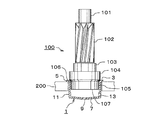
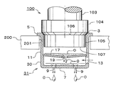
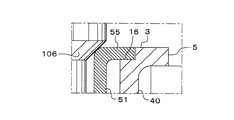
本発明に係る浸炭焼入れ焼もどし方法の第1の実施の形態について、図1ないし図4を参照して詳細に説明する。ただし、図1中に示したように、本形態方法において熱処理対象とする鋼製部品(ワーク)100は、例えば軸方向に長いヘリカルギア部品であり、図示、上から同軸で、小径円軸部101、ギア部102、円軸部103、大径円軸部104、およびこの大径円軸部104よりやや小径で、特定部分をなす非焼入れ部用円軸部(非焼入れ部ともいう)105とからなるものである。そして、その材質はNi−Cr鋼からなるものである。なお、各軸部はストレートに設定されている。そして、大径円軸部104の外径は、例えば28mmで、その軸方向の長さは8.5mm、そして非焼入れ部用円軸部105の外径は、例えば27.35mmで、その軸方向の長さは9mmに設定されており、大径円軸部104と非焼入れ部用円軸部105の間には、半径側において約0.3mmの径段部106が付けられて縮径されている。
A first embodiment of a carburizing and quenching tempering method according to the present invention will be described in detail with reference to FIGS. 1 to 4. However, as shown in FIG. 1, the steel part (workpiece) 100 to be heat-treated in the method of the present embodiment is, for example, a helical gear part that is long in the axial direction. 101, a
しかして、このような本形態において熱処理対象としている鋼製部品100は、その下端部の非焼入れ部用円軸部105が浸炭されないように、図示した有底筒(コップ)形状の浸炭防止用キャップ1が被せられ、そのキャップ1を下にして、詳しくは図示しない、例えば格子状のグリッドといわれるワーク保持体200の上に多数縦横に配置され、次のようにして熱処理される。なお、このグリッドといわれるワーク保持体200は、次記するようにキャップ1を介して鋼製部品100を保持するためと、焼入れ油に浸漬した際に油が循環、還流し易くなるように貫通した空孔が縦横に多数設けられたものである。
Therefore, the
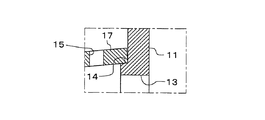
本形態において使用している浸炭防止用キャップ1は、例えば、SUS304からなる薄板を絞り又はプレス成形すると共に、一部に切削加工を加えて有底筒(コップ)形状に形成されている。ただし、本形態のキャップ1は、その上部をなす開口端縁3には半径外方に突出するようにリング状のフランジ5が形成されている。そして、このキャップ1に、鋼製部品100の非焼入れ部用円軸部105が、同キャップ1の外側部をなす筒状部11に内挿される形で隙間嵌され、その状態において、同キャップ1の開口端縁3のフランジ5の上端面の内周縁角が鋼製部品100の大径円軸部104と非焼入れ部用円軸部105の間の径段部106に当接するように設定されている。ただし、この内周縁角には微小Rからなる面取りが付けられている。しかして、このように隙間嵌された状態において、本形態では、非焼入れ部用円軸部105の端面107と底部7との間に5mm程度の空隙が保持され、非焼入れ部用円軸部105の外周面とキャップ1の外側壁面をなす円筒部11との間に0.1〜0.2mm程度の微小な隙間が保持されるように設定されている。
The
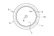
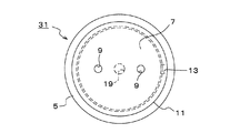
また、キャップ1の底部7は、中央が下向きに突出するような緩やかなテーパー状に形成されており、その中央には、平面視円形の油抜き穴9が本形態では一箇所貫通して設けられている。一方、キャップ1の外側壁面をなす円筒部11の下寄り部位には、円形をなす1つの空気流入穴13が貫通して設けられている。なお、本形態では、その油抜き穴9の径は4mmとされ、空気流入穴13の径は3mmとされている。また、この空気流入穴13の設けられている筒状部11の下寄り部位の内径は、本形態では段部14を介してやや小さく設定されている。
Further, the
しかして、キャップ1を非焼入れ部用円軸部105に被せ、その開口端縁3のフランジ5の上端面の内周縁角で、鋼製部品100を支持してなるキャップ付き鋼製部品を多数、保持体200の各空孔201の開口上端に、キャップ1のフランジ5の下面を係止させて配置させる。そして、次のようにして浸炭焼入れ、焼もどしをするのであるが、その際には次のようである。
Then, the
すなわち、このようなキャップ付き鋼製部品100をその浸炭防止用キャップ1を下にしてワーク保持体200の空孔201にキャップ1を介して配置し、浸炭性ガス雰囲気下にて所定の温度まで所定の昇温速度で加熱し、所定時間保持し、浸炭する。このとき、キャップ1が被せられている非焼入れ部用円軸部105は浸炭されない。なお、この浸炭においては、浸炭防止用キャップ1の油抜き穴9又は空気流入穴13から浸炭性ガスが若干還流するが、その穴は小さいため、実質的には浸炭処理されない。
That is, such a
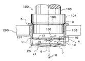
しかして、浸炭、加熱されたキャップ付き鋼製部品100を、ワーク保持体200に配置した状態において、焼入れ油中に浸漬する。こうすることで、キャップ1が被せられている非焼入れ部用円軸部105を除き、露出している部位の表面が浸炭焼入れされる。この焼入れ工程の後、焼入れしたキャップ付き鋼製部品100を、ワーク保持体200に配置した状態のままで焼入れ油中から引き上げる。すると、キャップ1と鋼製部品100との間(隙間)に入り込んだ焼き入れ油Oは、本形態ではその引き上げ後、油抜き穴9から図中矢印で示したように自然落下する。しかも、空気流入穴13が設けられていることから、そこから図中破線矢印で示したように空気が入りこむため、その円滑な排出がなされる。
Then, the
したがって、この後、焼もどし工程に送る前に、鋼製部品100を洗浄液にて洗浄するにあたって、キャップ1と鋼製部品100との間に入り込んでいた焼き入れ油は、その油抜き穴9から自然落下することで略存在しなくなっていることから、ワーク保持体200にキャップ1の付いた状態のままで、その鋼製部品100を洗浄液にて洗浄することができる。すなわち、従来のようにキャップ1を外してから鋼製部品100を洗浄しないと、隙間に存在する油が洗浄されないということがない。そして、その洗浄後には、焼もどし工程に送るのであるが、鋼製部品100の洗浄に際して、キャップ1の除去作業を要しないことから、その後は、従来のように、再度、ワーク保持体200への配置の工程を要することもない。かくして、本方法では、焼入れ後、キャップ1が付いた引き上げ後の状態のままで、洗浄工程からその後の焼もどし工程に送ることができる結果、熱処理工程の大幅な効率化が図られる。
Therefore, before the
このように本方法では、焼入れ後、焼入れ油中から引き上げた際に、キャップ1と鋼製部品100との隙間に存在している焼入れ油が自然落下できるように、キャップ1に、油抜き穴9が開口されているものを使用しているため、焼き入れ工程から洗浄工程さらにはその後の焼もどし工程に連続して送ることができるため、極めて効率的に熱処理ができる。とくに、本形態では、キャップ1に、油抜き穴9に加えて、空気流入穴13が設けられていることから、油の円滑な排出がなされるため、効率良く作業できる。
In this way, in this method, when the quenching oil is pulled out from the quenching oil after quenching, the
なお、前記形態で使用した浸炭防止用キャップ1は、その形状がコップ形状をなし、その側部に空気流入穴13を油抜き穴9とは別途に設けたものを使用したが、例えば、底部7の油抜き穴9をスリット状に細長く形成し、このスリットを側部の筒状部11まで連ねて形成しても同様の効果がある。また、空気流入穴13を油抜き穴9とは別途に設ける場合においては、両穴ともに複数設けてもよい。ただし、油抜き穴は、前記形態のキャップ1のように、引き上げた際において、焼入れ油が流れ込む流れ勾配の最下端部に開口するように設けるのが好ましい。そして、空気流入穴13は、空気の流入を容易とするため、その開口位置は、なるべく上の方に設けるのが好ましい。なお、油抜き穴9及び空気流入穴13の径が大きいほど油の落下が容易に行われるが、逆にその分、浸炭性ガスがキャップ内部に還流して、鋼製部品の非焼入れ部に接触する危険性が大きくなる。これらを考慮し、油抜き穴及び空気流入穴は、油の排出に支障のない範囲でなるべく小さくするとよい。
Note that the
さて、次に本発明に使用するキャップの第2の実施の形態について、図5及び図6を参照して説明する。ただし、本形態のキャップ21は、前記形態におけるキャップが1層のステンレスからなるものであるのに対し、キャップ本体20を深くし、2重底構造とした点のみが異なるだけであり、いわば前記形態の改良とでもいうべきものであるため、相違点のみ説明し、同一部位には同一の符号を付すに止める。すなわち、本形態のキャップ21は、その底部7寄り部位に、別設の内底(仕切り板)17を配置し、キャップ21の底のみ2層構造とした点のみが前記形態と相違するものであり、キャップ21の内側に前記形態における底部7と所定の間隙を保持するようにして、内底17をなすように仕切り板を段部14の上に載置するように別途取付けたものである。なお、この構造のものにおける内底(仕切り板)17にも、底部7と同様に平面視中央に、円形の油抜き穴19が設けられ、外周寄り部位に空気流入穴15が設けられている。また、内底(仕切り板)17は、中央が下向きに突出するような緩やかなテーパー状に形成されている。
Next, a second embodiment of the cap used in the present invention will be described with reference to FIGS. However, the
しかして、本形態では、このように内底17を設けたため、キャップ本体20の底部7に開けられた貫通穴9からガスが入り込んでも、内部の内底17にてそれ以上の侵入が一応遮蔽されるため、内底17と本体20の底部7との間に入り込むに止まり、内底17より鋼製部品100側に入り込むことを阻止できる。このため、浸炭性ガスに非焼入れ部が晒されることが有効に防止されるため、非焼入れ部が浸炭される危険性が低減される。そして、焼入れ後において焼入れ油中から引き上げた後、キャップ21内に存在する油Oのうち、内底17より上にあるものは本体20の底部7の上に落ち、さらに下方の外部に排出される。
In this embodiment, since the inner bottom 17 is provided in this way, even if gas enters through the through hole 9 formed in the
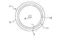
なお、本発明に使用するキャップは、図7及び図8に示した第3の実施の形態のキャップ31であってもよい。すなわち、図7及び図8に示したように、前記形態における内底17の油抜き穴19と、キャップ本体30の底部7の油抜き穴9とが平面的に同位置とならないようにしてもよい。
The cap used in the present invention may be the
このようにしておけば、鋼製部品100への浸炭性ガスの接触防止に一層有効である。すなわち、このようにしておけば、浸炭性ガスが底部7の油抜き穴9からキャップ31内に入り込んでも、内底17が効果的に邪魔板の作用をなすことから、鋼製部品100に接触するのを有効に防止する。これより明らかなように、浸炭性ガスの侵入による鋼製部品100の浸炭防止のため、両油抜き穴は平面的に見てなるべく離れた位置に配置するとよい。なお、図7及び図8に示したキャップ31においては、内底17の中央に油抜き穴19を設ける一方、底部7にはその外周寄り部位に油抜き穴9を設けたため、その底部7は平坦に形成している。
In this way, it is more effective for preventing the carburizing gas from contacting the
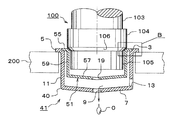
さらに、本発明に使用するキャップの第4の実施の形態について、図9及び図10を参照して説明するが、このものは、単なる二重底構造ではなく、底部7の上のみならず筒状部11の内側にも空間のある、複数(例えば2重)層からなるキャップ構造としたものである。ただし、この複数層からなるキャップ構造とした点のみが、前記第2又は第3の実施の形態と異なるだけで、それらと本質的相違はないことから、これまた相違点のみ説明し、同一部位には同一の符号を付すに止める。
Further, a fourth embodiment of the cap used in the present invention will be described with reference to FIGS. 9 and 10. This is not a simple double bottom structure, but a cylinder as well as a
すなわち、本形態では、図1のものと同様の構造からなるキャップ本体40の内側に、それより高さが低く、しかも直径の小さい有底筒(コップ)形状の内キャップ51を配置したものである。詳しくは、内キャップ51の筒状部59の上端部外周に形成したリング状フランジ55を介して、キャップ本体40の筒状部11の上端部内側に形成した凹段部16に嵌合するようにして支持させたものである。本形態では、内キャップ51の底部(内底)57を、中央が下向きに突出するような緩やかなテーパー状に形成し、その中央に、平面視円形の油抜き穴19を貫通して設けている。そして、内キャップ51の筒状部(周部)59を円筒状にしてキャップ本体40の内側に同軸状にして配置し、内キャップ51の筒状部59と本体40の筒状部11との間と、内キャップ51の底部57と本体40の底部7との間に空間を保持するようにしたものである。
That is, in this embodiment, the
上記においては、キャップを有底筒(コップ)形状のものとして具体化したが、これについては、鋼製部品の形状に応じて適宜の形状とすれば良い。そして、いずれの形状のキャップとする場合でも、鋼製部品の非焼入れ部に被せた際において、キャップの開口端縁(開口端縁角)と鋼製部品とが当接するように、鋼製部品におけるキャップの開口端縁との境界部位には、キャップが被さらないで鋼製部品面が大径をなすように段差を形成しておくとよい。このようにしてあると、浸炭防止用キャップと鋼製部品との隙間に、キャップの開口端縁側から浸炭性ガスが入り込むのを有効に防止できるためである。なお、段差は、30〜60度の範囲での面取り状にして形成するか、Rの隅肉にて形成しておくとよい。一方、この段差に当接する、キャップの開口端縁(開口端縁角)は、0.2〜0.8mm程度のR面取りを付けておくとよい。というのは、キャップはコストや耐久性からみてSUS製とされる一方、SUSのものは、浸炭焼入れされる鋼製部品より、熱膨張係数が大きいため、加熱過程で鋼製部品が深く入り込んで嵌合し、冷却により焼き嵌め状態ないし食い付きを起しがちとなる。しかし、キャップの開口端縁にこの程度のR面取りが付けてあれば、それが防止できるためである。 In the above description, the cap is embodied as a bottomed cylinder (cup) shape, but this may be an appropriate shape according to the shape of the steel part. And even if it is set as a cap of any shape, when it covers on the non-hardened part of steel parts, it is steel parts so that the opening edge (opening edge angle) of a cap and steel parts may contact. It is preferable to form a step at a boundary portion with the opening end edge of the cap so that the steel part surface has a large diameter without covering the cap. This is because the carburizing gas can be effectively prevented from entering the gap between the carburizing prevention cap and the steel part from the opening edge side of the cap. The step is preferably formed in a chamfered shape in the range of 30 to 60 degrees, or formed with an R fillet. On the other hand, the opening edge (opening edge angle) of the cap that is in contact with the step is preferably provided with an R chamfer of about 0.2 to 0.8 mm. This is because caps are made of SUS in terms of cost and durability, but SUS has a larger coefficient of thermal expansion than steel parts that are carburized and hardened, so that steel parts penetrate deeply during the heating process. When fitted, it tends to cause shrinkage or biting by cooling. However, this is because it is possible to prevent such chamfering at the opening edge of the cap.
本発明の方法に使用するキャップは、上記した実施の形態のものに限定されるものではなく、その要旨を逸脱しない範囲において適宜に設計変更して具体化できる。例えば、上記の各形態における浸炭防止用キャップは、開口端が円形のカップ形状のものを具体化したが、多角形のものとしても具体化できる。そして、キャップの材質は、SUS304以外で形成しても良いし、鋼製部品と同材質であってもよい。さらに、異なる材質製とする場合には、なるべく熱膨張係数が同じものにすると良い。 The cap used in the method of the present invention is not limited to the above-described embodiment, and can be embodied by changing the design as appropriate without departing from the scope of the invention. For example, the carburizing prevention cap in each of the above embodiments is embodied in a cup shape having a circular opening end, but may be embodied in a polygonal shape. And the material of a cap may be formed other than SUS304, and may be the same material as steel parts. Furthermore, when making it from a different material, it is good to make a thermal expansion coefficient the same as much as possible.
なお、本発明の浸炭焼入れ焼もどし方法に適用する鋼製部品は、上記においては、軸線方向に長いハスバ歯車としたが、本発明は、その他の歯車や軸部品にも適用できるし、長寸状でない鋼製部品にも適用できる。つまり、鋼製部品の特定部分に浸炭性ガスにて浸炭されないように浸炭防止用キャップを被せて浸炭焼入れ焼もどしする各種の部品に適用できる。 In the above description, the steel part applied to the carburizing and quenching tempering method of the present invention is a helical gear that is long in the axial direction. However, the present invention can also be applied to other gears and shaft parts, and is long. It can also be applied to steel parts that are not shaped. That is, the present invention can be applied to various parts that are carburized, quenched, and tempered by putting a carburizing prevention cap so that a specific part of the steel part is not carburized by the carburizing gas.
1、21、31、41 浸炭防止用キャップ
3 浸炭防止用キャップの開口端縁
9、19 油抜き穴
13、15 空気流入穴
100 鋼製部品
200 ワーク保持体
O 浸炭防止用キャップと鋼製部品との間に存在している焼入れ油
1,21,31,41
Claims (3)
焼入れした該浸炭防止用キャップ付き鋼製部品を前記ワーク保持体に配置した状態のままで該焼入れ油中から引き上げた際に、該浸炭防止用キャップと鋼製部品との間に存在している焼入れ油が自然落下できるように、前記浸炭防止用キャップに、油抜き穴が開口されているものを使用することを特徴とする、鋼製部品の浸炭焼入れ焼もどし方法。 Cover a specific part of the steel part with a carburizing prevention cap so that it is not carburized by carburizing gas, and place the steel part with the carburizing prevention cap on the upper edge of the carburizing prevention cap. Carburizing and quenching by placing in a workpiece holder, heating in a carburizing gas atmosphere, carburizing, and immersing the heated steel parts with the carburizing prevention cap in the quenching oil in the state of being placed on the workpiece holder And a step of lifting the hardened steel part with a cap for preventing carburization while being placed on the workpiece holder from the quenching oil, and then cleaning the quenched steel part, In a carburizing and quenching tempering method for steel parts, comprising a tempering step after a cleaning step,
When the hardened steel part with the carburizing prevention cap is placed on the workpiece holder and pulled up from the quenching oil, it exists between the carburizing prevention cap and the steel part. A carburizing and quenching and tempering method for steel parts, wherein the carburizing prevention cap has an oil drain hole opened so that the quenching oil can fall naturally.
Priority Applications (1)
| Application Number | Priority Date | Filing Date | Title |
|---|---|---|---|
| JP2005140283A JP2005298977A (en) | 2005-05-12 | 2005-05-12 | Method for carburizing, quenching, and tempering steel part |
Applications Claiming Priority (1)
| Application Number | Priority Date | Filing Date | Title |
|---|---|---|---|
| JP2005140283A JP2005298977A (en) | 2005-05-12 | 2005-05-12 | Method for carburizing, quenching, and tempering steel part |
Related Parent Applications (1)
| Application Number | Title | Priority Date | Filing Date |
|---|---|---|---|
| JP2001227689A Division JP3706555B2 (en) | 2001-07-27 | 2001-07-27 | Carburizing, quenching and tempering of steel parts |
Publications (1)
| Publication Number | Publication Date |
|---|---|
| JP2005298977A true JP2005298977A (en) | 2005-10-27 |
Family
ID=35330876
Family Applications (1)
| Application Number | Title | Priority Date | Filing Date |
|---|---|---|---|
| JP2005140283A Pending JP2005298977A (en) | 2005-05-12 | 2005-05-12 | Method for carburizing, quenching, and tempering steel part |
Country Status (1)
| Country | Link |
|---|---|
| JP (1) | JP2005298977A (en) |
Cited By (2)
| Publication number | Priority date | Publication date | Assignee | Title |
|---|---|---|---|---|
| JP2016540899A (en) * | 2013-10-22 | 2016-12-28 | ディケイ‐ロック・コーポレイションDk‐Lok Corporation | Partial heat treatment method using double metal layer |
| CN117778673A (en) * | 2024-01-03 | 2024-03-29 | 常州市岩棣达金属科技有限公司 | Low-carbon medium-alloy/high-alloy carburizing steel infiltration carbon quenching method |
-
2005
- 2005-05-12 JP JP2005140283A patent/JP2005298977A/en active Pending
Cited By (2)
| Publication number | Priority date | Publication date | Assignee | Title |
|---|---|---|---|---|
| JP2016540899A (en) * | 2013-10-22 | 2016-12-28 | ディケイ‐ロック・コーポレイションDk‐Lok Corporation | Partial heat treatment method using double metal layer |
| CN117778673A (en) * | 2024-01-03 | 2024-03-29 | 常州市岩棣达金属科技有限公司 | Low-carbon medium-alloy/high-alloy carburizing steel infiltration carbon quenching method |
Similar Documents
| Publication | Publication Date | Title |
|---|---|---|
| JP4650981B2 (en) | Method and apparatus for peening | |
| JP5581805B2 (en) | Method for plating stainless steel material and plating material thereof | |
| JP2009084607A (en) | Tool for decompression heat treatment, and decompression heat treatment method | |
| TWI602231B (en) | A substrate processing apparatus, a deposit removal method for a substrate processing apparatus, and a storage medium | |
| JP3706555B2 (en) | Carburizing, quenching and tempering of steel parts | |
| JP2005298977A (en) | Method for carburizing, quenching, and tempering steel part | |
| JP4771766B2 (en) | Process method and processing apparatus | |
| EP0880929A2 (en) | Insulating double-layered container | |
| CN101023285A (en) | Component with internal teeth and method for producing same | |
| JPH1121631A (en) | Method for hardening thin sheet parts | |
| KR101873367B1 (en) | Method for cooling metal parts having undergone a nitriding/nitrocarburizing treatment in a molten salt bath, unit for implementing said method and the treated metal parts | |
| JP4137435B2 (en) | Heat treatment apparatus and heat treatment method | |
| JP2018024904A (en) | Cooling device and cooling method | |
| CN112458396B (en) | Surface treatment process of non-stick, perforation-resistant and high-thermal-conductivity uncoated carbon steel frying pan | |
| FI58357C (en) | FOERFARANDE FOER SEPARATION AV EN ELEKTROLYTISK METALLFAELLNING | |
| JP2008022837A (en) | Soup machine | |
| KR102116275B1 (en) | Shielding unit, device treating substrate, and method for treating substrate using the sames | |
| JP3606502B2 (en) | Carburizing method and carburizing jig used in the carburizing method | |
| KR20140010219A (en) | A manufacture method of cookware and cookware | |
| JP3005576U (en) | Strainer for tempura pan | |
| KR101516525B1 (en) | Wire cooling vat | |
| JP2958711B2 (en) | Gas nitrocarburizing method | |
| JPH0734118A (en) | Top of molten metal container in vacuum container | |
| KR101427201B1 (en) | Manufacturing method of cooking vessel with groove on the bottom | |
| JP2024009556A (en) | Method for manufacturing laminate and bearing ring |