JP2005298866A - Deposition equipment - Google Patents
Deposition equipment Download PDFInfo
- Publication number
- JP2005298866A JP2005298866A JP2004114159A JP2004114159A JP2005298866A JP 2005298866 A JP2005298866 A JP 2005298866A JP 2004114159 A JP2004114159 A JP 2004114159A JP 2004114159 A JP2004114159 A JP 2004114159A JP 2005298866 A JP2005298866 A JP 2005298866A
- Authority
- JP
- Japan
- Prior art keywords
- gas
- source
- film
- source gas
- forming apparatus
- Prior art date
- Legal status (The legal status is an assumption and is not a legal conclusion. Google has not performed a legal analysis and makes no representation as to the accuracy of the status listed.)
- Granted
Links
Images


Landscapes
- Chemical Vapour Deposition (AREA)
Abstract
Description
本発明は、少なくともZn原料ガスとO原料ガスにより、被処理物の表面にZnO膜の成膜を行う成膜装置に関するものである。 The present invention relates to a film forming apparatus for forming a ZnO film on the surface of an object to be processed using at least a Zn source gas and an O source gas.
白色の発光ダイオード(LED)等の発光素子に使用されるZnOエピタキシャル膜は、一般的にMBE(Molecular Beam Epitaxy)装置やMO−CVD(Metal Organic−Chemical Vapor Deposition)装置が成膜装置として採用されている。これらの装置では、プラズマやレーザーを用いて、原料ガスの分解アシストを行い、ZnO成膜の形成効率を高めている。
上記のMBE装置やMO−CVD装置等のように、プラズマ源やレーザー源を成膜装置に組み付けることは、構造的に複雑になるとともに設備費用の高騰を招くという問題がある。また、既存の成膜装置にプラズマ源やレーザー源を付加することについても、上記の場合と同様な問題がある。さらに、プラズマ等の利用により、原料ガスの分解がより一層活性化されるが、反面、副生成物堆積によるパーティクルが発生しやすくなり、膜質劣化等に弊害をもたらす恐れが生じる。 As in the MBE apparatus and the MO-CVD apparatus, assembling the plasma source and the laser source into the film forming apparatus has a problem that the structure becomes complicated and the equipment cost increases. Further, adding a plasma source or a laser source to an existing film forming apparatus has the same problem as the above case. Furthermore, the use of plasma or the like further activates the decomposition of the source gas, but on the other hand, particles are more likely to be generated due to by-product deposition, which may cause adverse effects on film quality degradation and the like.
本発明は、上記のような事情に鑑みなされたもので、処理空間に分解ガスを導入し、特別な設備改造を伴うことなく、ZnO成膜の成長を促進させる成膜装置の提供を目的とする。 The present invention has been made in view of the above circumstances, and an object thereof is to provide a film forming apparatus that introduces decomposition gas into a processing space and promotes the growth of ZnO film formation without any special equipment modification. To do.
上記目的を達成するため、本発明の成膜装置は、処理空間内に少なくともZn原料ガスとO原料ガスを供給し、上記両原料ガスにより上記処理空間に露出している被処理物の表面にZnO膜の成膜を行う成膜装置であって、少なくとも上記両原料ガスのいずれかの分解を促進する分解ガスを上記処理空間内に導入する分解ガス導入路を備えていることを要旨とする。 In order to achieve the above object, the film forming apparatus of the present invention supplies at least a Zn source gas and an O source gas into a processing space, and is applied to the surface of the object to be processed exposed to the processing space by the both source gases. A film forming apparatus for forming a ZnO film, comprising: a decomposition gas introduction path for introducing at least a decomposition gas that promotes decomposition of either of the two source gases into the processing space. .
本発明の成膜装置は、少なくとも上記両原料ガスのいずれかの分解を促進する分解ガスを上記処理空間内に導入する分解ガス導入路を備えている。このため、上記両原料ガスのいずれかの分解が分解ガスによって促進されるので、それとともに被処理物の表面に形成される成膜の成長速度が向上し、ZnO成膜の形成時間が短縮され、生産性が向上する。また、被処理物を加熱して成膜する成膜装置の場合には、上記の成膜形成時間の短縮により、加熱のための熱エネルギー費用の低減に有効である。原料ガスを分解する手段として分解ガスが採用されているので、従来技術のように、プラズマやレーザーを採用することが回避でき、成膜設備の構造簡素化や設備費用の低減に有効である。同時に、副生成物堆積によるパーティクルが発生しにくくなり、膜質劣化等が回避できる。さらに、分解ガスとして、Zn原料である有機金属材料の分解促進に効果的な水素ガスを選定することも可能となり、有機金属材料が分解しにくくなる低温域においても、水素が被処理物の表面に留まりやすいので、有機金属材料の分解効果が発揮され、良好な成膜成長がなされる。 The film forming apparatus of the present invention includes a cracked gas introduction path for introducing a cracked gas for promoting the decomposition of at least one of the two source gases into the processing space. For this reason, since the decomposition of either of the two source gases is promoted by the decomposition gas, the growth rate of the film formed on the surface of the object to be processed is improved, and the formation time of the ZnO film is shortened. , Improve productivity. Further, in the case of a film forming apparatus for heating an object to be processed to form a film, it is effective to reduce the heat energy cost for heating by shortening the film forming time. Since cracked gas is used as a means for decomposing the source gas, it is possible to avoid using plasma and laser as in the prior art, and it is effective for simplifying the structure of the film forming equipment and reducing equipment costs. At the same time, particles due to by-product accumulation are less likely to occur, and film quality degradation and the like can be avoided. Furthermore, it is possible to select a hydrogen gas that is effective for promoting the decomposition of the organometallic material, which is a Zn raw material, as a decomposition gas. Therefore, the decomposition effect of the organometallic material is exhibited, and favorable film growth is achieved.
一方、上記のように水素ガスを選定することができるので、O原料ガス特に酸素との反応により微量な水分H2Oが発生し、これがZn原料である有機金属材料の一部と反応して反応の基点を作り、Zn+O→ZnOの反応が促進される。 On the other hand, since the hydrogen gas can be selected as described above, a trace amount of water H 2 O is generated by the reaction with the O raw material gas, particularly oxygen, and this reacts with a part of the organometallic material that is the Zn raw material. The base point of the reaction is created, and the reaction of Zn + O → ZnO is promoted.
本発明の成膜装置において、上記分解ガスと、当該分解ガスの分解対象となる原料ガスとを処理空間内に供給する第1供給流路が設けられている場合には、上記第1供給流路内において上記分解対象となる原料ガスが分解ガスによって分解され、分解された原料ガスが被処理物の表面に成膜成長が促進されやすい状態で到達する。このため、成膜の成長速度が速まり、生産性が向上する。 In the film forming apparatus of the present invention, when the first supply flow path for supplying the decomposition gas and the source gas to be decomposed into the decomposition gas into the processing space is provided, the first supply flow The raw material gas to be decomposed is decomposed by the decomposition gas in the passage, and the decomposed raw material gas reaches the surface of the object to be processed in a state where film growth is easily promoted. For this reason, the growth rate of film formation is increased, and the productivity is improved.
本発明の成膜装置において、上記第1供給流路とは別個に設けられ、上記分解対象となる原料ガスと異なる原料ガスを処理空間内に供給する第2供給流路を備えている場合には、分解対象となる原料ガスと分解ガスとが流通する流路すなわち第1供給流路と、他の異なる原料ガスが流通する流路すなわち第2供給流路とが別個に独立した状態で成立する。このため、第1供給流路を流通する原料ガスと分解ガスが、第2供給流路を流通する他の異なる原料ガスから区分された状態で、被処理物の表面に供給することができ、被処理物表面における分解ガスで分解された原料ガスや他の異なる原料ガスの供給状態が、成膜形成ないしは成膜成長速度の向上にとって最適化される。 The film forming apparatus of the present invention includes a second supply channel that is provided separately from the first supply channel and supplies a source gas different from the source gas to be decomposed into the processing space. Is established in a state where the flow path through which the source gas to be decomposed and the cracked gas flow, ie, the first supply flow path, and the flow path through which other different source gas flows, ie, the second supply flow path, are independent. To do. For this reason, the source gas and the cracked gas that circulate through the first supply channel can be supplied to the surface of the object to be processed in a state separated from other different source gases that circulate through the second supply channel, The supply state of the raw material gas decomposed by the decomposition gas on the surface of the object to be processed and other different raw material gases are optimized for the film formation or the improvement of the film growth rate.
本発明の成膜装置において、上記分解ガスを上記両原料ガスとは別個に処理空間内に供給する第3供給流路が設けられている場合には、分解ガスだけが独立した流路すなわち第3供給流路を経て処理空間内に供給されるので、分解ガスの種類,流量,被処理物に対する噴出状態等の各種条件に適合させることが行ないやすくなる。 In the film forming apparatus of the present invention, when a third supply flow path for supplying the cracked gas into the processing space separately from the two source gases is provided, only the cracked gas is an independent flow path, that is, a first flow path. Since the gas is supplied into the processing space via the three supply channels, it is easy to adapt to various conditions such as the type of decomposition gas, the flow rate, and the ejection state of the object to be processed.
本発明の成膜装置において、上記処理空間内に、上記Zn原料ガス,O原料ガスおよび分解ガスを被処理物の表面に対して噴出する複数の噴出開口を接近した位置関係で開口した場合には、各噴出開口からのZn原料ガス,O原料ガスおよび分解ガスが接近した箇所から流出するので、原料ガスの分解やその後の他の原料ガスとの反応が成膜の良好な成長にとって適正な状態で進行する。 In the film forming apparatus of the present invention, when a plurality of ejection openings for ejecting the Zn source gas, the O source gas, and the decomposition gas to the surface of the object to be processed are opened in the processing space in a close positional relationship. Since the Zn source gas, the O source gas and the decomposition gas from the respective jet openings flow out from close locations, the decomposition of the source gas and the subsequent reaction with other source gases are appropriate for good growth of the film formation. Progress in state.
本発明の成膜装置において、上記噴出開口のうちの1つが上記第1供給流路である場合には、上記噴出開口のうちの1つから上記分解対象となる原料ガスが分解ガスによって分解された状態で噴出するので、分解されるべき原料ガスは良好な分解状態になって、被処理物の表面に成膜成長が促進されやすい状態で到達する。このため、成膜の成長速度が速まり、生産性が向上する。 In the film forming apparatus of the present invention, when one of the ejection openings is the first supply channel, the source gas to be decomposed is decomposed by the decomposition gas from one of the ejection openings. Therefore, the raw material gas to be decomposed is in a good decomposition state and reaches the surface of the object to be processed in a state where film growth is easily promoted. For this reason, the growth rate of film formation is increased, and the productivity is improved.
本発明の成膜装置において、上記複数の噴出開口は、上記Zn原料ガス,O原料ガスおよび分解ガスがそれぞれ独立して導入される複数の拡散室に連通し、各噴出開口からZn原料ガス,O原料ガスおよび分解ガスをそれぞれ独立して噴射させる場合には、各ガスの流れに脈動や乱流状態があっても各拡散室において緩衝されるので、上記各噴出開口から流出する各ガスの流れが整流状態となり、被処理物の表面に作用する処理ガス雰囲気が成膜形成およびその形成速度向上にとって最適化される。また、各拡散室からそれぞれ第1供給流路,第2供給流路,第3供給流路が分岐して各噴出開口に連通しているので、各噴出開口における流出ガス量が略均一になり、被処理物の表面の成膜成長がムラなく均一に進行し、よりすぐれた成膜品質が確保できる。 In the film forming apparatus of the present invention, the plurality of ejection openings communicate with a plurality of diffusion chambers into which the Zn source gas, the O source gas, and the decomposition gas are independently introduced, and each of the ejection openings has a Zn source gas, When the O source gas and the cracked gas are injected independently, each gas flow is buffered in each diffusion chamber even if there is a pulsation or turbulent flow state. The flow becomes a rectifying state, and the processing gas atmosphere acting on the surface of the object to be processed is optimized for the film formation and the formation speed improvement. In addition, since the first supply channel, the second supply channel, and the third supply channel branch from each diffusion chamber and communicate with each ejection opening, the amount of outflow gas at each ejection opening becomes substantially uniform. The film growth on the surface of the object to be processed proceeds uniformly without unevenness, and a better film quality can be ensured.
本発明の成膜装置において、上記分解ガスの分解対象となる原料ガスが、Zn原料ガスである場合には、上記Zn原料ガスからZn元素が分解され、このZn元素がO原料ガスと反応して良好なZnO膜の成膜が進行する。さらに、分解ガスとして、Zn原料である有機金属材料の分解促進に効果的な水素ガスを選定することができるので、有機金属材料が分解しにくくなる低温域においても、水素が被処理物の表面に留まりやすいので、有機金属材料の分解効果が発揮され、良好な成膜成長がなされる。 In the film forming apparatus of the present invention, when the source gas to be decomposed of the decomposition gas is a Zn source gas, Zn element is decomposed from the Zn source gas, and the Zn element reacts with the O source gas. The formation of a good ZnO film proceeds. Furthermore, since hydrogen gas that is effective in promoting the decomposition of the organometallic material that is the Zn raw material can be selected as the decomposition gas, hydrogen can be removed from the surface of the workpiece even in a low temperature range where the organometallic material is difficult to decompose. Therefore, the decomposition effect of the organometallic material is exhibited, and favorable film growth is achieved.
本発明の成膜装置において、上記分解ガスがHまたはH基を含むガスである場合には、上記HまたはH基を含むガスが分解ガスとして、Zn原料である有機金属材料の分解促進に効果的に作用し、上記Zn原料ガスからZn元素が分解され、このZn元素がO原料ガスと反応して良好なZnO膜の成膜が進行する。さらに、有機金属材料が分解しにくくなる低温域においても、水素が被処理物の表面に留まりやすいので、有機金属材料の分解効果が発揮され、良好な成膜成長がなされる。原料ガスを分解する手段としてHまたはH基を含むガスが採用されているので、従来技術のように、プラズマやレーザーを採用することが回避でき、成膜設備の構造簡素化や設備費用の低減に有効である。さらに、水素ガスを分解ガスとすることにより、O原料ガス特に酸素との反応により微量な水分H2Oが発生し、これがZn原料である有機金属材料の一部と反応して反応の基点を作り、Zn+O→ZnOの反応が促進される。 In the film forming apparatus of the present invention, when the decomposition gas is a gas containing H or H group, the gas containing H or H group is effective as a decomposition gas for promoting the decomposition of the organometallic material that is a Zn raw material. The Zn element is decomposed from the Zn source gas, and the Zn element reacts with the O source gas, so that a good ZnO film is formed. Furthermore, since hydrogen tends to stay on the surface of the object to be processed even in a low temperature range where the organic metal material is difficult to decompose, the decomposition effect of the organic metal material is exhibited and favorable film growth is achieved. Since gas containing H or H group is used as a means for decomposing the source gas, it is possible to avoid using plasma and laser as in the prior art, simplifying the structure of film deposition equipment and reducing equipment costs It is effective for. Furthermore, by using hydrogen gas as the cracked gas, a trace amount of water H 2 O is generated by reaction with O source gas, particularly oxygen, and this reacts with a part of the organometallic material that is Zn source to set the base point of the reaction. The reaction of Zn + O → ZnO is promoted.
つぎに、本発明を実施するための最良の形態を説明する。以下の説明では、Zn原料ガスの分解ガスとして水素ガスを用い、O原料ガスとともに被処理物の表面におけるZnO膜を、高い膜成長速度のもとに成膜する。 Next, the best mode for carrying out the present invention will be described. In the following description, hydrogen gas is used as a decomposition gas for the Zn source gas, and a ZnO film on the surface of the object to be processed is formed at a high film growth rate together with the O source gas.
図1〜図4は、本発明の成膜装置の一実施例を示す。 1 to 4 show an embodiment of a film forming apparatus of the present invention.
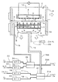
図1は、成膜装置の全体構造を示す断面図である。この装置は、内部が処理空間1とされた処理容器2内に分離板3が設けられ、分離板3にあけた開口4に合致させた状態で被処理物である板状のサファイア基板5が載置されている。サファイア基板5の裏面の上方に加熱ヒータHが配置されて、加熱エリア1Aが形成されている。また、分離板3やサファイア基板5の下側の処理空間1が、各種の処理ガスが供給される成長エリア1Bとされている。そして、処理空間1を真空にする真空ポンプ(図示していない)が配置され、排気口6から処理空間1内が真空排気されるようになっている。なお、8は加熱用のリフレクタである。
FIG. 1 is a cross-sectional view showing the overall structure of the film forming apparatus. In this apparatus, a
上記サファイア基板5に対する処理ガスすなわち原料ガスや分解ガス等の供給は、供給流路から処理空間1内すなわち成長エリア1Bに対して行なわれる。この例では、成長エリア1B内へ供給される処理ガスはガス噴出ヘッド7を経由するようになっている。上記ガス噴出ヘッド7は、上記分離板3やそれに載置されたサファイア基板5の下側の成長エリア1B内に配置されている。このガス噴出ヘッド7から噴射された処理ガスにより、サファイア基板5の表面にCVD(Chemical Vaper Deposition)処理が施されて、白色LED等の発光素子に用いられるZnOエピタキシャル膜や絶縁用の酸化膜あるいは配線用の金属膜等が成膜される。
The processing gas, that is, the raw material gas or the decomposition gas is supplied to the
この実施例は、原料ガスとしてZn原料ガスとO原料ガスが用いられ、また、Zn原料ガスに対する分解ガスとしてHまたはH基を含むガスである水素ガスが用いられている。原料ガスは、Zn原料ガスにはDEZn(ジ・エチル亜鉛)が採用され、O原料ガスには酸素(O2)と亜酸化窒素(N2O)が採用されている。上記の原料ガスや分解ガスを用いてサファイア基板5の表面にZnO膜を成膜する。
In this embodiment, a Zn source gas and an O source gas are used as source gases, and a hydrogen gas that is a gas containing H or H groups is used as a decomposition gas for the Zn source gas. As the source gas, DEZn (diethylzinc) is adopted as the Zn source gas, and oxygen (O 2 ) and nitrous oxide (N 2 O) are adopted as the O source gas. A ZnO film is formed on the surface of the
ガス噴出ヘッド(シャワーヘッドとも呼ばれている)7は、仕切り板9を介して第1拡散室10と第2拡散室11に区画され、上記第1拡散室10には後述の第1供給流路15が開口し、また、上記第2拡散室11には後述の第2供給流路16が開口している。第2拡散室11のサファイヤ基板5側には、当該サファイア基板5に面した状態で開口板12が配置されている。上記開口板12には、図2に拡大して示すように、複数の噴出開口13,14が接近した状態で配置されている。1つの噴出開口13は開口板12に直接設けた円形の穴13Aであり、もう1つの噴出開口14は上記噴出開口13よりも小径の断面円形のパイプ14Aである。上記穴13Aは第2拡散室11に連通しており、上記パイプ14Aは仕切り板9を貫通して第1拡散室10に連通している。したがって、噴出開口13すなわち穴13Aと噴出開口14すなわちパイプ14Aは同心状に配置されて、接近した位置関係になっている。
A gas ejection head (also called a shower head) 7 is partitioned into a
上記第1供給流路15を、分解対象となるDEZnガスと、DEZnガスに対する分解ガスである水素ガスとが所定の流量比率で流通する。DEZnガスと水素ガスの流路17,18には、それぞれマスフローコントローラ(流量調節計)19,20が配置され、両流路17,18は切換弁21に接続され、上記切換弁21に第1供給流路15が接続されているとともに、ベント通路21Aが接続されている。DEZnガスや水素ガスは、それぞれマスフローコントローラ(流量調節計)19,20で所定の流量に設定され、初期の段階ではベント通路21Aから処理設備(図示していない)を経て系外に放出される。その後、両ガスの流量比が所定値に安定してから切換弁21を切換えることにより、DEZnガスと水素ガスとが第1拡散室10に供給される。
Through the
上記第2供給流路16を、O原料ガスである酸素と亜酸化窒素とが所定の流量比率で流通する。酸素と亜酸化窒素の流路22,23には、それぞれマスフローコントローラ(流量調節計)24,25が配置され、両流路22,23は切換弁26に接続され、上記切換弁26に第2供給流路16が接続されているとともに、ベント通路26Aが接続されている。酸素と亜酸化窒素は、それぞれマスフローコントローラ(流量調節計)24,25で所定の流量に設定され、初期の段階ではベント通路26Aから処理設備(図示していない)を経て系外に放出される。その後、両ガスの流量比が所定値に安定してから切換弁26を切換えることにより、酸素と亜酸化窒素とが第2拡散室11に供給される。なお、酸素と亜酸化窒素は特に相互反応をしないので、上記のように共通の通路である第2供給流路16から混合状態で供給することができるが、酸素と亜酸化窒素を別々の供給流路で供給することもできる。このように別々に供給することにより、両ガスの被処理物に対する噴出状態を適切な条件に適合させやすくなる。
Through the
上記のように、第1供給流路15と第2供給流路16とは別個に設けられ、分解対象となるDEZnガスは第1供給流路15を流通して、第1拡散室10に供給される。他方、分解対象となっていない酸素と亜酸化窒素は第2供給流路16を流通して、第2拡散室11に供給される。
As described above, the first
第1供給流路15内を流通するZn原料ガスや水素ガス等は、それらが流動中に水素ガスによりZn原料ガスが分解され、Zn原料ガスは良好な分解状態になってパイプ14Aからサファイア基板5の表面に供給される。したがって、第1供給流路15は、切換弁21から延びるパイプ部材15Aと、上記パイプ部材15Aが開口している第1拡散室10と、第1拡散室10から開口板12まで伸びているパイプ14Aによって構成されている。また、第2供給流路16もそこを流れるO原料ガスが、開口板12を出た箇所から分解されたZn元素との反応が開始されるので、第1供給流路15と同様に、切換弁26から穴13Aまでにわたって存在している。
The Zn source gas, hydrogen gas, and the like flowing through the
上記の成膜装置の動作を、図3に示したZnO成膜シーケンスに関連させて説明する。成膜装置の成膜シーケンスは、基板クリーニング,バッファ層成長,高温層成長の3段階である。 The operation of the film forming apparatus will be described in relation to the ZnO film forming sequence shown in FIG. The film forming sequence of the film forming apparatus is in three stages: substrate cleaning, buffer layer growth, and high temperature layer growth.
最初の基板クリーニングは、サファイア基板5の膜成長面の状態をコントロールし、成膜の成長を促進するために行なわれ、その方法として真空中やガス雰囲気での熱処理がなされる。この例では、水素ガス雰囲気中で、加熱ヒータHによって加熱されたサファイア基板の温度を約1000℃に保っている。この基板クリーニングの段階では、DEZn,O2,N2Oの供給はなされていない。上記基板クリーニングを実施するために、処理空間1を真空状態とし、上記マスフローコントローラ(流量調節計)20,切換弁21および加熱ヒータHの制御装置(図示していない)を動作させて、水素ガス雰囲気中で、サファイア基板5の温度を約1000℃に保っている。基板クリーニングにおける水素ガスは、第1供給流路15から第1拡散室10に供給され、パイプ14Aからサファイア基板5の表面に吹き付けられる。
The first substrate cleaning is performed in order to control the state of the film growth surface of the
次の段階であるバッファ層成長は、低温でZnO単結晶膜を成長させ、その後の高温層成長を助長させるために行なわれる。上記基板クリーニング終了後、処理空間1の真空状態を維持し、加熱ヒータHの制御装置を動作させて、約5分間でサファイア基板5の温度を約400℃に安定させる。この安定状態になってから、切換弁21および26を切り換えて、DEZnとH2とが所定の流量比率のもとに第1供給流路15から第1拡散室10に供給され、パイプ14Aを経てサファイア基板5の表面に吹き付けられる。この吹き付けと同時に、O2とN2Oとが所定の流量比率のもとに第2供給流路16から第2拡散室11に供給され、穴13Aを経てサファイア基板5の表面に吹き付けられる。以上のようにDEZnガスがH2で分解されながら、O2とN2Oとともにサファイア基板5の表面に噴射されて、バッファ層の成長がなされる。なお、この段階で形成されたZnO単結晶膜の目標膜厚は、30〜40nmである。
The next step, buffer layer growth, is performed to grow a ZnO single crystal film at a low temperature and to facilitate the subsequent high-temperature layer growth. After completion of the substrate cleaning, the
最後の段階である高温層成長は、サファイア基板温度を600〜800℃に設定してZnO成膜を行う。この段階では、確実な成膜を進行させるために、各原料ガスや分解ガス等の処理ガスを供給する前に真空度を高め、さらに、加熱ヒータHの制御装置を動作させてサファイア基板5の温度を600〜800℃の高温に維持し、その後、上記バッファ層成長の段階と同様にして、各マスフローコントローラ(流量調節計)19,20,24,25並びに切換弁21,26を動作させる。この段階での成長圧力は、10−3〜1Pa(10−5〜10−2Torr)である。これにより、DEZnとH2とが所定の流量比率のもとに第1供給流路15から第1拡散室10に供給され、パイプ14Aを経てサファイア基板5の表面に吹き付けられる。この吹き付けと同時に、O2とN2Oとが所定の流量比率のもとに第2供給流路16から第2拡散室11に供給され、穴13Aを経てサファイア基板5の表面に吹き付けられる。以上のようにDEZnガスがH2によってZn元素に分解されながら、O2とN2Oとともにサファイア基板5の表面に噴射されて、Zn元素とO原料ガスが反応し、ZnO成膜の成長が図られる。その後、所定の膜厚に達したとき、各ガスの供給を停止し加熱ヒータHの加熱も停止して、サファイア基板5が成膜装置から取り出される。なお、上記バッファ層成長および高温層成長における反応式は、Zn+O→ZnOとZn+N2O→ZnO+N2である。そして、この段階で形成されるZnO成膜の目標膜厚は、2μmである。
In the final high-temperature layer growth, the sapphire substrate temperature is set to 600 to 800 ° C., and ZnO film formation is performed. At this stage, in order to advance the reliable film formation, the degree of vacuum is increased before supplying the processing gas such as each source gas and decomposition gas, and the control device of the heater H is operated to operate the
上記高温層成長の段階では、高温であるためにZnO膜の表層から還元が進行しないようにすることが必要である。そのために、O2とN2Oを真空状態を維持しながらDEZnとH2の供給停止後も流し続けて加熱温度を下げて行くようにしている。このような還元防止の措置を講じることにより、ZnO成膜の厚さが正常に確保され、成膜時間の短縮にも効果的である。上記のO2とN2Oの供給延長時間は、図3において符合Tで示されている。 At the stage of the high temperature layer growth, since the temperature is high, it is necessary to prevent the reduction from proceeding from the surface layer of the ZnO film. For this purpose, O 2 and N 2 O are kept flowing even after the supply of DEZn and H 2 is stopped while maintaining the vacuum state, and the heating temperature is lowered. By taking such measures to prevent reduction, the thickness of the ZnO film formation can be ensured normally, and the film formation time can be shortened. The O 2 and N 2 O supply extension time is indicated by the symbol T in FIG.
図4は、DEZn供給量に対するZnO成長速度の関係を示している。同図において、H2の流量がゼロである場合は、ZnOの成長速度は0.05μm/hrであるのに対し、H2の流量を10sccmとした場合には、0.1395μm/hrとなり、H2の供給により、ZnOの成長速度は約2.8倍になったことが認められる。同図におけるTgはサファイア基板5の温度であり、Thは加熱ヒータHの温度である。
FIG. 4 shows the relationship of the ZnO growth rate to the DEZn supply amount. In the figure, when the flow rate of H 2 is zero, the growth rate of ZnO is 0.05 μm / hr, whereas when the flow rate of H 2 is 10 sccm, it becomes 0.1395 μm / hr. It can be seen that the growth rate of ZnO has increased by about 2.8 times due to the supply of H 2 . Tg in the figure is the temperature of the
上記実施例では,サファイア基板5が被処理物とされているが、これをZnO基板とし、その表面にZnO膜をホモ成長で形成することも可能である。
In the above embodiment, the
上記分解ガスは、水素ガスであるが、それ以外のものとしては、H基を含むガスが使用可能であり、例えばアセチレン(C2H2),エチレン(C2H4),ベンゼン(C2H6)等である。 The cracked gas is hydrogen gas, but as other gas, gas containing H group can be used. For example, acetylene (C 2 H 2 ), ethylene (C 2 H 4 ), benzene (C 2 H 6 ) and the like.
また、上記実施例では、O2とN2Oを所定の流量比率で供給するものであるが、O2とN2Oを独立させて別々に供給することも可能である。 In the above embodiment, O 2 and N 2 O are supplied at a predetermined flow rate ratio, but O 2 and N 2 O can be supplied separately and separately.
上記実施例の構成により、上記Zn原料ガスであるDEZnの分解が分解ガスである水素ガスによって促進されるので、分解されたZn元素と酸素との反応により、サファイア基板5の表面に形成されるZnO成膜の成長速度が向上し、ZnO成膜の形成時間が短縮され、生産性が向上する。また、サファイア基板5を加熱して成膜する成膜装置の場合には、上記の成膜形成時間の短縮により、加熱のための熱エネルギー費用の低減に有効である。Zn原料ガスを分解するガスとして水素ガスが採用されているので、従来技術のように、プラズマやレーザーを採用することが回避でき、成膜設備の構造簡素化や設備費用の低減に有効である。さらに、分解ガスとして、Zn原料である有機金属材料の分解促進に効果的な水素ガスを選定することができるので、有機金属材料が分解しにくくなる低温域においても、水素がサファイア基板5の表面に留まりやすいので、有機金属材料の分解効果が発揮され、良好な成膜成長がなされる。
With the configuration of the above embodiment, the decomposition of DEZn, which is the Zn source gas, is promoted by hydrogen gas, which is the decomposition gas, so that it is formed on the surface of the
一方、上記のように水素ガスを選定することができるので、O原料ガス特に酸素との反応により微量な水分H2Oが発生し、これがZn原料である有機金属材料の一部と反応して反応の基点を作り、Zn+O→ZnOの反応が促進される。さらに、O原料として水(H2O)を付加することにより、上記のZn+O→ZnOの反応が促進される。 On the other hand, since the hydrogen gas can be selected as described above, a trace amount of water H 2 O is generated by the reaction with the O raw material gas, particularly oxygen, and this reacts with a part of the organometallic material that is the Zn raw material. The base point of the reaction is created, and the reaction of Zn + O → ZnO is promoted. Furthermore, the reaction of Zn + O → ZnO is promoted by adding water (H 2 O) as an O raw material.
上記第1供給流路15内において、上記分解対象となるDEZnガスが、分解ガスである水素ガスによってZn元素に分解され、分解されたDEZnガスがサファイア基板5の表面に成膜成長が促進されやすい状態で到達する。このため、成膜の成長速度が速まり、生産性が向上する。
In the first
分解対象となるDEZnガスと水素ガスとが流通する流路すなわち第1供給流路15と、他の異なる原料ガスであるO原料ガスが流通する流路すなわち第2供給流路16とが別個に独立した状態で成立している。このため、第1供給流路15を流通するDEZnガスと水素ガスが、第2供給流路16を流通する他の異なるO原料ガスから区分された状態で、サファイア基板5の表面に供給することができ、サファイア基板5の表面における水素ガスで分解されたZn元素やO原料ガスの供給状態が、成膜形成ないしは成膜成長速度の向上にとって最適化される。また、膜質向上や低パーティクル化が実現するのであるが、それはDEZnガスと水素ガスとが第1供給流路15から供給されるので、O原料ガスとの反応によるH2O生成がサファイア基板5の表面に限定されているためと考えられる。
The flow path through which DEZn gas and hydrogen gas to be decomposed flow, that is, the first
上記処理空間1(成長エリア1B)内に、上記Zn原料ガス,O原料ガスおよび分解ガスをサファイア基板5の表面に対して噴出する複数の噴出開口すなわち穴13A,パイプ14Aを接近した位置関係で設けてあるので、各穴13A,パイプ14AからのZn原料ガス,O原料ガスおよび分解ガスが接近した箇所から流出し、原料ガスの分解やその後の反応が成膜の良好な成長にとって適正な状態で進行する。さらに、上記複数の噴出開口、例えば、穴13Aとパイプ14Aの組合わせを、サファイア基板5の大きさ等に応じて複数組配置することにより、ZnO成膜の処理ガス雰囲気を良好に形成することができる。
In the processing space 1 (growth area 1B), the Zn source gas, the O source gas, and the decomposition gas are jetted to the surface of the
上記穴13A,パイプ14Aのうちのパイプ14Aが上記第1供給流路15とされていることにより、一方のパイプ14AからZn原料ガスが水素ガスによって分解された状態で噴出するので、分解されるべきZn原料ガスは良好な分解状態になって、サファイア基板5の表面に成膜成長が促進されやすい状態で到達する。このため、成膜の成長速度が速まり、生産性が向上する。
Since the
上記分解ガスの分解対象となる原料ガスが、Zn原料ガスであるから、上記Zn原料ガスからZn元素が分解され、このZn元素がO原料ガスと反応して良好なZnO膜の成膜が進行する。さらに、分解ガスとして、Zn原料である有機金属材料の分解促進に効果的な水素ガスが選定されているので、有機金属材料が分解しにくくなる低温域においても、水素がサファイア基板5の表面に留まりやすいので、有機金属材料の分解効果が発揮され、良好な成膜成長がなされる。
Since the source gas to be decomposed of the cracked gas is a Zn source gas, Zn element is decomposed from the Zn source gas, and this Zn element reacts with the O source gas, so that a good ZnO film is formed. To do. Furthermore, since hydrogen gas that is effective in promoting the decomposition of the organometallic material that is the Zn raw material is selected as the decomposition gas, hydrogen is present on the surface of the
上記水素ガスが分解ガスとして、Zn原料である有機金属材料の分解促進に効果的に作用し、有機金属材料が分解しにくくなる低温域においても、水素がサファイア基板5の表面に留まりやすいので、有機金属材料の分解効果が発揮され、良好なZnO膜成長がなされる。原料ガスを分解する手段として水素ガスが採用されているので、従来技術のように、プラズマやレーザーを採用することが回避でき、成膜設備の構造簡素化や設備費用の低減に有効である。さらに、水素ガスを分解ガスとすることにより、O原料ガス特に酸素との反応により微量な水分H2Oが発生し、これがZn原料である有機金属材料の一部と反応して反応の基点を作り、Zn+O→ZnOの反応が促進される。
The hydrogen gas acts as a decomposition gas, effectively acts to promote the decomposition of the organometallic material that is the Zn raw material, and hydrogen tends to stay on the surface of the
Zn原料ガスを供給する第1供給流路15やO原料ガスを供給する第2供給流路16とは別個に、処理空間1内に水素ガスを供給する流路を設けることができる。すなわち、図1に2点鎖線で示すように、第3供給流路27が第1拡散室10に開口しており、上記第3供給流路27の途中にマスフローコントローラ(流量調節計)28が配置してある。
A flow path for supplying hydrogen gas into the
上記第3供給流路27を設けることにより、水素ガスだけが独立した流路すなわち第3供給流路を経て処理空間1内に供給されるので、分解ガスの種類,流量,サファイア基板5に対する噴出状態等の各種条件に適合させることが行ないやすくなる。
By providing the third
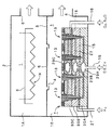
図5および図6は、本発明の成膜装置の第2の実施例を示す。 5 and 6 show a second embodiment of the film forming apparatus of the present invention.
この実施例は、複数の噴出開口が、上記Zn原料ガス,O原料ガスおよび分解ガスがそれぞれ独立して導入される複数の拡散室に連通し、各噴出開口からZn原料ガス,O原料ガスおよび分解ガスをそれぞれ独立して噴射させるものである。図5は、処理容器2全体の断面図であり、図6は、ガス噴出ヘッド7の一部を拡大した断面図である。図示していないが、ガス噴出ヘッド7の平面形状は円形であり、その表面に多数の噴出開口13がサファイア基板5の表面に均一なZnO成膜が形成できるように設けられている。
In this embodiment, a plurality of ejection openings communicate with a plurality of diffusion chambers into which the Zn source gas, the O source gas, and the decomposition gas are independently introduced, and the Zn source gas, the O source gas, and the The cracked gas is injected independently. FIG. 5 is a sectional view of the
この例では、平面形状が円形とされた略ドーム型の拡散室29A,29B,29Cが、分厚い積層部材30A,30B,30Cの中央部にそれぞれ独立した室の状態で構成されている。DEZnを供給する第1供給流路15は、ガス噴出ヘッド7の外部から噴出開口13に連通しており、この第1供給流路15の途中に拡散室29Aが配置されている。また、水素ガスを供給する第3供給流路27は、ガス噴出ヘッド7の外部から噴出開口13に連通しており、この第3供給流路27の途中に拡散室29Bが配置されている。さらに、O原料ガスを供給する第2供給流路16は、ガス噴出ヘッド7の外部から噴出開口13に連通しており、この第2供給流路16の途中に拡散室29Cが配置されている。上記のように、各拡散室29A,29B,29Cはそれぞれ独立しているので、拡散室29AにはDEZnだけが供給され、拡散室29Bには水素ガスだけが供給され、また、拡散室29CにはO原料ガスだけが供給される。
In this example, substantially dome-shaped
上記噴出開口13は、図6に示されているように、積層部材30Cに設けた円形の開口31内に大径パイプ32を挿入して環状の流通間隙33を形成し、上記大径パイプ32の内側に小径パイプ34を挿入して環状の流通間隙35を形成し、さらに、小径パイプ34自体の内側が流通路36とされている。上記流通路36は第1供給流路15と、上記流通間隙35は第3供給流路27と、上記流通間隙33は第2供給流路16にそれぞれ連通している。それ以外は、上記実施例と同様であり、同様の部分には同じ符号を付している。
As shown in FIG. 6, the ejection opening 13 forms an
上記構成により、各ガスの流れに脈動や乱流状態があっても各拡散室29A,29B,29Cにおいて緩衝されるので、上記各噴出開口33,35,36から流出する各ガスの流れが整流状態となり、サファイア基板5の表面に作用する処理ガス雰囲気が成膜形成およびその形成速度向上にとって最適化される。また、各拡散室29A,29B,29Cからそれぞれ第1供給流路15,第3供給流路27,第2供給流路16が分岐して各噴出開口36,35,33に連通しているので、各噴出開口36,35,33における流出ガス量が略均一になり、サファイア基板5の表面の成膜成長がムラなく均一に進行し、よりすぐれた成膜品質が確保できる。それ以外は、上記実施例と同様の作用効果を奏する。
With the above configuration, even if there is a pulsation or a turbulent flow state in each gas, it is buffered in each
なお、上記実施例1において、第1供給流路15にDEZnと水素ガスを同時に流し、第3供給流路27には何も流さないか、あるいは何等かの他のガスを供給するようにすることも可能である。
In the first embodiment, DEZn and hydrogen gas are simultaneously supplied to the first
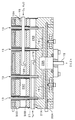
図7および図8は、本発明の成膜装置の第3の実施例を示す。 7 and 8 show a third embodiment of the film forming apparatus of the present invention.
この実施例は、拡散室の形状を変更したもので、図7は、ガス噴出ヘッド7の断面図、図8は、噴出開口13の部分を拡大して示した断面図である。上記積層部材30Cと30Bの間に広くて偏平な円形の空間を設けて、その空間を拡散室29Cとして構成し、上記積層部材30Bと30Aの間に広くて偏平な円形の空間を設けて、その空間を拡散室29Bとして構成し、積層部材30Aの中央部に空間容積の大きな凹部を設けてそこを拡散室29Aにしたものである。また、第2供給流路16は供給管16Aを外部から拡散室29C内に挿入し、その先端部に拡散室29Cの略中央部に開口する噴口16Bを設けてある。さらに、第3供給流路27は供給管27Aを外部から拡散室29B内に挿入し、その先端部に拡散室29Bの略中央部に開口する噴口27Bを設けてある。それ以外は、上記各実施例と同様であり、同様の部分には同じ符号を付している。
In this embodiment, the shape of the diffusion chamber is changed. FIG. 7 is a sectional view of the
上記構成により、広くて偏平な円形の空間とされた拡散室29B,29Cの中央部に、それぞれ噴口16B,27BからO原料ガスおよび水素ガスが供給され、各噴出開口13に対して均等な流量のガス流出が可能となり、サファイア基板5の表面全域に均一な品質のZnO成膜が形成できる。それ以外は、上記各実施例と同様の作用効果を奏する。
With the above configuration, O source gas and hydrogen gas are supplied from the
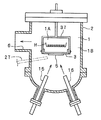
図9は、本発明の成膜装置の第4の実施例を示す。 FIG. 9 shows a fourth embodiment of the film forming apparatus of the present invention.
この実施例は、図1に示した加熱エリア1Aが、処理空間1内において独立した加熱ボックス37の状態で形成され、その下側にサファイア基板5が取り付けられている。DEZnと水素ガスを供給する第1供給流路15が、処理容器2の外部から処理空間1内に挿入され、O原料ガスを供給する第2供給流路16が、処理容器2の外部から処理空間1内に挿入され、各第1供給流路15および第2供給流路16はサファイア基板5の表面に各処理ガスを吹き付けるようになっている。なお、第3供給流路27を2点鎖線図示のように配置して、水素ガスを供給することも可能である。それ以外は、上記各実施例と同様であり、同様の部分には同じ符号を付している。
In this embodiment, the heating area 1A shown in FIG. 1 is formed in the state of an
上記構成により、サファイア基板5の表面に、水素ガスで分解されたZn元素およびO原料ガスが吹き付けられ、ZnO膜が形成される。それ以外は、上記各実施例と同様の作用効果を奏する。
With the above configuration, Zn element decomposed with hydrogen gas and O source gas are sprayed onto the surface of the
プラズマ源やレーザー源を成膜装置に組み込んだり、既存の成膜装置を改造してプラズマ源やレーザー源を装備するような経済的な負担を回避して、分解ガスの供給により簡単な成膜設備で品質的に安定したZnO成膜が可能となり、白色発光ダイオード等の発光素子の製造等に適用することができる。 Easy deposition by supplying decomposition gas, avoiding the economic burden of incorporating a plasma source or laser source into the deposition system, or modifying an existing deposition system to equip the plasma source or laser source. ZnO film formation that is stable in quality can be performed by the equipment, and can be applied to manufacture of a light emitting element such as a white light emitting diode.
1 処理空間
1A 加熱エリア
1B 成長エリア
2 処理容器
3 分離板
4 開口
5 被処理物,サファイア基板,ZnO基板
6 排気口
7 ガス噴出ヘッド
H 加熱ヒータ
8 リフレクタ
9 仕切り板
10 第1拡散室
11 第2拡散室
12 開口板
13 噴出開口
13A 穴
14 噴出開口
14A パイプ
15 第1供給流路
15A パイプ部材
16 第2供給流路
16A 供給管
16B 噴口
17 流路
18 流路
19 マスフローコントローラ(流量調節計)
20 マスフローコントローラ(流量調節計)
21 切換弁
21A ベント通路
22 流路
23 流路
24 マスフローコントローラ(流量調節計)
25 マスフローコントローラ(流量調節計)
26 切換弁
26A ベント通路
T 延長時間
27 第3供給流路
27A 供給管
27B 噴口
28 マスフローコントローラ(流量調節計)
29A 拡散室
29B 拡散室
29C 拡散室
30A 積層部材
30B 積層部材
30C 積層部材
31 開口
32 大径パイプ
33 流通間隙
34 小径パイプ
35 流通間隙
36 流通路
37 加熱ボックス
DESCRIPTION OF
20 Mass flow controller (flow controller)
21 Switching valve
25 Mass Flow Controller (Flow Controller)
26
Claims (9)
Priority Applications (1)
| Application Number | Priority Date | Filing Date | Title |
|---|---|---|---|
| JP2004114159A JP4133911B2 (en) | 2004-04-08 | 2004-04-08 | Deposition equipment |
Applications Claiming Priority (1)
| Application Number | Priority Date | Filing Date | Title |
|---|---|---|---|
| JP2004114159A JP4133911B2 (en) | 2004-04-08 | 2004-04-08 | Deposition equipment |
Publications (2)
| Publication Number | Publication Date |
|---|---|
| JP2005298866A true JP2005298866A (en) | 2005-10-27 |
| JP4133911B2 JP4133911B2 (en) | 2008-08-13 |
Family
ID=35330779
Family Applications (1)
| Application Number | Title | Priority Date | Filing Date |
|---|---|---|---|
| JP2004114159A Expired - Fee Related JP4133911B2 (en) | 2004-04-08 | 2004-04-08 | Deposition equipment |
Country Status (1)
| Country | Link |
|---|---|
| JP (1) | JP4133911B2 (en) |
Cited By (2)
| Publication number | Priority date | Publication date | Assignee | Title |
|---|---|---|---|---|
| JP2010070398A (en) * | 2008-09-16 | 2010-04-02 | Stanley Electric Co Ltd | Method for growing zinc oxide single crystal layer |
| US7691203B2 (en) * | 2006-01-27 | 2010-04-06 | Air Water Inc. | Film forming apparatus |
-
2004
- 2004-04-08 JP JP2004114159A patent/JP4133911B2/en not_active Expired - Fee Related
Cited By (2)
| Publication number | Priority date | Publication date | Assignee | Title |
|---|---|---|---|---|
| US7691203B2 (en) * | 2006-01-27 | 2010-04-06 | Air Water Inc. | Film forming apparatus |
| JP2010070398A (en) * | 2008-09-16 | 2010-04-02 | Stanley Electric Co Ltd | Method for growing zinc oxide single crystal layer |
Also Published As
| Publication number | Publication date |
|---|---|
| JP4133911B2 (en) | 2008-08-13 |
Similar Documents
| Publication | Publication Date | Title |
|---|---|---|
| US9315897B2 (en) | Showerhead for film depositing vacuum equipment | |
| JP4700602B2 (en) | Semiconductor vapor deposition process and apparatus using two kinds of process gas pretreated on one side | |
| CN110904432B (en) | MOCVD reactor | |
| US20090250004A1 (en) | Gas Head and Thin-Film Manufacturing Apparatus | |
| JP4840832B2 (en) | Vapor phase growth apparatus, vapor phase growth method, and semiconductor device manufacturing method | |
| US20070266932A1 (en) | Vapor phase growth apparatus and method for vapor phase growth | |
| TWI725951B (en) | Method and apparatus for deposition of a iii-v semiconductor layer | |
| JP2016164994A (en) | Multiple-level showerhead design | |
| KR20120053003A (en) | Hollow cathode showerhead | |
| CN112695302B (en) | MOCVD reactor | |
| US20080017108A1 (en) | Gas combustion apparatus | |
| JP2008540990A (en) | Gas combustion equipment | |
| JP4544898B2 (en) | Method for forming ZnO film | |
| JP2011222592A (en) | Vapor phase deposition apparatus and vapor phase deposition method | |
| JP4133911B2 (en) | Deposition equipment | |
| JP2005005594A (en) | Semiconductor manufacturing device | |
| KR100407507B1 (en) | Gas injector for ALD device | |
| JP4663912B2 (en) | Semiconductor manufacturing equipment | |
| JP4879693B2 (en) | MOCVD apparatus and MOCVD method | |
| KR100744528B1 (en) | Plasma atomic layer deposition apparatus and method using gas separation shower head to which RF power is applied | |
| KR101013492B1 (en) | Chemical vapor deposition apparatus and control method thereof | |
| JP3168277B2 (en) | Semiconductor crystal growth equipment | |
| KR20090055871A (en) | Shower head type gas supply device and gas supply method for semiconductor deposition equipment | |
| KR101573522B1 (en) | Nozzle Unit of MOCVD Apparatus | |
| KR20120090349A (en) | A chemical vapor deposition apparatus |
Legal Events
| Date | Code | Title | Description |
|---|---|---|---|
| A977 | Report on retrieval |
Free format text: JAPANESE INTERMEDIATE CODE: A971007 Effective date: 20070423 |
|
| A131 | Notification of reasons for refusal |
Free format text: JAPANESE INTERMEDIATE CODE: A131 Effective date: 20070508 |
|
| A521 | Request for written amendment filed |
Free format text: JAPANESE INTERMEDIATE CODE: A523 Effective date: 20070705 |
|
| A131 | Notification of reasons for refusal |
Free format text: JAPANESE INTERMEDIATE CODE: A131 Effective date: 20071204 |
|
| A521 | Request for written amendment filed |
Free format text: JAPANESE INTERMEDIATE CODE: A523 Effective date: 20080118 |
|
| TRDD | Decision of grant or rejection written | ||
| A01 | Written decision to grant a patent or to grant a registration (utility model) |
Free format text: JAPANESE INTERMEDIATE CODE: A01 Effective date: 20080520 |
|
| A01 | Written decision to grant a patent or to grant a registration (utility model) |
Free format text: JAPANESE INTERMEDIATE CODE: A01 |
|
| A61 | First payment of annual fees (during grant procedure) |
Free format text: JAPANESE INTERMEDIATE CODE: A61 Effective date: 20080602 |
|
| FPAY | Renewal fee payment (event date is renewal date of database) |
Free format text: PAYMENT UNTIL: 20110606 Year of fee payment: 3 |
|
| R150 | Certificate of patent or registration of utility model |
Ref document number: 4133911 Country of ref document: JP Free format text: JAPANESE INTERMEDIATE CODE: R150 Free format text: JAPANESE INTERMEDIATE CODE: R150 |
|
| FPAY | Renewal fee payment (event date is renewal date of database) |
Free format text: PAYMENT UNTIL: 20110606 Year of fee payment: 3 |
|
| FPAY | Renewal fee payment (event date is renewal date of database) |
Free format text: PAYMENT UNTIL: 20120606 Year of fee payment: 4 |
|
| R250 | Receipt of annual fees |
Free format text: JAPANESE INTERMEDIATE CODE: R250 |
|
| FPAY | Renewal fee payment (event date is renewal date of database) |
Free format text: PAYMENT UNTIL: 20120606 Year of fee payment: 4 |
|
| FPAY | Renewal fee payment (event date is renewal date of database) |
Free format text: PAYMENT UNTIL: 20130606 Year of fee payment: 5 |
|
| R250 | Receipt of annual fees |
Free format text: JAPANESE INTERMEDIATE CODE: R250 |
|
| R250 | Receipt of annual fees |
Free format text: JAPANESE INTERMEDIATE CODE: R250 |
|
| R250 | Receipt of annual fees |
Free format text: JAPANESE INTERMEDIATE CODE: R250 |
|
| R250 | Receipt of annual fees |
Free format text: JAPANESE INTERMEDIATE CODE: R250 |
|
| R250 | Receipt of annual fees |
Free format text: JAPANESE INTERMEDIATE CODE: R250 |
|
| R250 | Receipt of annual fees |
Free format text: JAPANESE INTERMEDIATE CODE: R250 |
|
| R250 | Receipt of annual fees |
Free format text: JAPANESE INTERMEDIATE CODE: R250 |
|
| R250 | Receipt of annual fees |
Free format text: JAPANESE INTERMEDIATE CODE: R250 |
|
| R250 | Receipt of annual fees |
Free format text: JAPANESE INTERMEDIATE CODE: R250 |
|
| R250 | Receipt of annual fees |
Free format text: JAPANESE INTERMEDIATE CODE: R250 |
|
| R250 | Receipt of annual fees |
Free format text: JAPANESE INTERMEDIATE CODE: R250 |
|
| LAPS | Cancellation because of no payment of annual fees |