JP2005298413A - High-efficiency synthetic process for methanol and apparatus therefor - Google Patents
High-efficiency synthetic process for methanol and apparatus therefor Download PDFInfo
- Publication number
- JP2005298413A JP2005298413A JP2004117554A JP2004117554A JP2005298413A JP 2005298413 A JP2005298413 A JP 2005298413A JP 2004117554 A JP2004117554 A JP 2004117554A JP 2004117554 A JP2004117554 A JP 2004117554A JP 2005298413 A JP2005298413 A JP 2005298413A
- Authority
- JP
- Japan
- Prior art keywords
- methanol
- catalyst
- cooling
- reaction
- raw material
- Prior art date
- Legal status (The legal status is an assumption and is not a legal conclusion. Google has not performed a legal analysis and makes no representation as to the accuracy of the status listed.)
- Granted
Links
Images
Classifications
-
- Y—GENERAL TAGGING OF NEW TECHNOLOGICAL DEVELOPMENTS; GENERAL TAGGING OF CROSS-SECTIONAL TECHNOLOGIES SPANNING OVER SEVERAL SECTIONS OF THE IPC; TECHNICAL SUBJECTS COVERED BY FORMER USPC CROSS-REFERENCE ART COLLECTIONS [XRACs] AND DIGESTS
- Y02—TECHNOLOGIES OR APPLICATIONS FOR MITIGATION OR ADAPTATION AGAINST CLIMATE CHANGE
- Y02P—CLIMATE CHANGE MITIGATION TECHNOLOGIES IN THE PRODUCTION OR PROCESSING OF GOODS
- Y02P20/00—Technologies relating to chemical industry
- Y02P20/50—Improvements relating to the production of bulk chemicals
- Y02P20/52—Improvements relating to the production of bulk chemicals using catalysts, e.g. selective catalysts
Landscapes
- Devices And Processes Conducted In The Presence Of Fluids And Solid Particles (AREA)
- Organic Low-Molecular-Weight Compounds And Preparation Thereof (AREA)
- Low-Molecular Organic Synthesis Reactions Using Catalysts (AREA)
Abstract
Description
本発明は、平衡転化率を超える転化率で、水素および酸化炭素を主成分とする原料ガスからメタノールを合成する方法及びそのための装置に関する。 The present invention relates to a method for synthesizing methanol from a raw material gas mainly composed of hydrogen and carbon oxide at a conversion rate exceeding an equilibrium conversion rate, and an apparatus therefor.
メタノール(メチルアルコール)は、燃料として、また脂肪、樹脂、ワニス等の溶媒として、さらにホルマリンの製造原料、メチル化剤、エチルアルコールの変性などに用いられ、工業的には、水性ガスを原料として200℃〜300℃の温度域で、5MPa〜10MPaといった高圧下に、銅・亜鉛を主成分とする触媒上で反応させて合成される。水素と一酸化炭素を主成分とする原料ガスからメタノールを合成するときの主反応は、次の通りである。 Methanol (methyl alcohol) is used as a fuel, as a solvent for fats, resins, varnishes, etc., and as a raw material for production of formalin, methylating agent, modification of ethyl alcohol, etc. It is synthesized by reacting on a catalyst mainly composed of copper / zinc under a high pressure of 5 MPa to 10 MPa in a temperature range of 200 ° C. to 300 ° C. The main reaction when synthesizing methanol from a raw material gas mainly containing hydrogen and carbon monoxide is as follows.
![]()
![]()
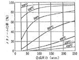
メタノール合成の主反応は分子数減少反応であり、かつ高発熱反応である。メタノール合成の主反応である上記化1式の反応平衡におけるメタノール化率、温度、圧力の関係を図5に示す。図5から明らかなように、メタノール合成反応は低温、高圧であるほど有利であるが、実装置においては、経済的な観点から合成条件として、200℃〜300℃の温度域、5MPa〜10MPaの圧力域が採用されている。水素および一酸化炭素を主成分とする原料ガス中には二酸化炭素も含まれており、下記逆シフト反応により一酸化炭素に転化し、さらに化1式の主反応によってメタノールが合成される。 The main reaction in methanol synthesis is a molecular number reduction reaction and a highly exothermic reaction. FIG. 5 shows the relationship between the methanolization rate, temperature, and pressure in the reaction equilibrium of the above formula 1, which is the main reaction of methanol synthesis. As is clear from FIG. 5, the methanol synthesis reaction is more advantageous as the temperature is lower and the pressure is higher. However, in an actual apparatus, as a synthesis condition from an economical point of view, a temperature range of 200 ° C. to 300 ° C., 5 MPa to 10 MPa. Pressure range is adopted. Carbon dioxide is also contained in the raw material gas mainly composed of hydrogen and carbon monoxide, which is converted into carbon monoxide by the following reverse shift reaction, and methanol is synthesized by the main reaction of the chemical formula 1.
![]()
![]()
また、二酸化炭素は下記反応によって直接メタノールに転化される。 Carbon dioxide is directly converted to methanol by the following reaction.
![]()
![]()
メタノール合成反応は大きな発熱反応である処から、熱に弱い特性をもつ銅系触媒を有効に機能させるために、反応触媒層の温度制御がきわめて重要である。而して、従来、反応容器内に形成される触媒充填層内に二重管構造の冷却管を多数配設して、冷却管内管外壁面と外管内壁面との間の環状空間に冷却水を流通・上昇せしめて外管内壁面で熱交換し、水と水蒸気の混合流体を内管上端開口から下降せしめて下部に設けられているチャンバに集め、水蒸気ノズル排出口から流出せしめるようにして触媒層を所望の温度に維持するよう構成したメタノール合成反応器が既知である(たとえば、特許文献1参照)。
しかしながら、従来技術において、発熱反応であるメタノール合成によって生じた熱は種々の手段によって系外に取り出されるが、何れも生成するメタノールの蒸気圧の露点以上の冷却温度である。このように従来技術においては、冷却温度が生成するメタノールの蒸気圧の露点以上であるために、平衡転化率を超える転化率の下でのメタノール合成が不可能であり、また転化率が平衡値に近づくと原料濃度が低下するために反応速度が低下し、反応器の効率が著しく低下する問題がある。 However, in the prior art, the heat generated by the synthesis of methanol, which is an exothermic reaction, is taken out of the system by various means. Thus, in the prior art, since the cooling temperature is equal to or higher than the dew point of the vapor pressure of methanol produced, methanol synthesis under a conversion rate exceeding the equilibrium conversion rate is impossible, and the conversion rate is equal to the equilibrium value. As the concentration approaches, the raw material concentration decreases, so the reaction rate decreases, and the efficiency of the reactor is significantly reduced.
本発明は、簡潔、コンパクトな反応器で平衡転化率を超える転化率下に、水素および酸化炭素を原料としてメタノール合成を遂行することができる反応プロセスを提供することを目的とする。 An object of the present invention is to provide a reaction process capable of carrying out methanol synthesis using hydrogen and carbon oxide as raw materials under a conversion rate exceeding the equilibrium conversion rate in a simple and compact reactor.
上記課題を解決するための請求項1に記載の発明は、水素と酸化炭素を主成分とする原料ガスを、触媒の存在下に反応させてメタノールを合成する方法であって、触媒層内に生成メタノールの蒸気圧の露点以下の冷却面を存在せしめ、該冷却面においてメタノールを液化、滴下させて反応系外に抜き出し、平衡転化率を超える転化率下にメタノール合成を遂行せしめるようにしたメタノールの高効率合成法である。 The invention according to claim 1 for solving the above-mentioned problem is a method for synthesizing methanol by reacting a raw material gas mainly composed of hydrogen and carbon oxide in the presence of a catalyst. Methanol that has a cooling surface below the dew point of the vapor pressure of the produced methanol, liquefies methanol on the cooling surface, drops it out of the reaction system, and performs methanol synthesis at a conversion rate exceeding the equilibrium conversion rate This is a highly efficient synthesis method.
請求項2に記載の発明は、水素と酸化炭素を主成分とする原料ガスを、触媒の存在下に反応させてメタノールを合成する方法であって、反応容器の内部に一又は複数の多孔円筒を配置し、該多孔円筒外周面と前記反応容器の内周面間に触媒充填部を形成するとともに、前記多孔円筒内部に前記触媒充填部で合成されたメタノールの蒸気圧の露点以下の冷却面を有する冷却体を存在せしめて、前記冷却面において生成メタノールを液化、滴下させて該液状メタノールを反応系外に抜き出すようにしたメタノールの高効率合成法である。
The invention according to
請求項3に記載の発明は、水素と酸化炭素を主成分とする原料ガスを、触媒の存在下に反応させてメタノールを合成するメタノール製造装置であって、反応容器と、該反応容器内に一又は複数配置される多孔円筒と、前記反応容器内周面および多孔円筒外周面間に形成される触媒重点部と、前記多孔円筒内部に配設される、前記触媒重点部における生成メタノールの蒸気圧の露点以下の冷却面をもつとともに冷媒流通手段を有する冷却体と、該冷却体における冷却面において液化、滴下するメタノールを反応系外に抜き出し回収するメタノール回収部とを有するメタノール製造装置である。 The invention according to claim 3 is a methanol production apparatus for synthesizing methanol by reacting a raw material gas mainly composed of hydrogen and carbon oxide in the presence of a catalyst, comprising: a reaction vessel; and One or a plurality of perforated cylinders, a catalyst emphasis portion formed between the inner peripheral surface of the reaction vessel and the outer perimeter surface of the porous cylinder, and vapor of generated methanol in the catalyst emphasis portion disposed inside the porous cylinder A methanol production apparatus comprising a cooling body having a cooling surface below a dew point of pressure and having a refrigerant circulation means, and a methanol recovery unit for extracting and recovering methanol liquefied and dropped from the reaction system on the cooling surface of the cooling body. .
本発明によれば、簡潔、コンパクトな反応器で平衡転化率を超える転化率下でのメタノール合成を1パスで達成できる。また、反応系において、未反応ガスをリサイクルするシステムが不要となるため、反応装置が著しく単純化される。さらに、小型の装置であっても高い生産性を持ち得る。また、生成メタノールの冷却を水で行えば50℃〜80℃の温水を得ることができる。 According to the present invention, methanol synthesis at a conversion rate exceeding the equilibrium conversion rate can be achieved in one pass in a simple and compact reactor. Further, since a system for recycling unreacted gas is not required in the reaction system, the reaction apparatus is remarkably simplified. Furthermore, even a small device can have high productivity. Moreover, if the produced methanol is cooled with water, hot water of 50 ° C. to 80 ° C. can be obtained.
以下、本発明をその好ましい実施形態に則して説明する。
本発明は、水素および酸化炭素(CO、CO2)を原料ガスとして、平衡転化率を超える転化率でメタノール合成を行う反応プロセスである。本発明は、触媒層中にそこでのメタノール蒸気圧の露点以下の冷却面を存在させて、この冷却面において生成メタノールを液化させ、この液相のメタノールを反応系外に抜き出すことによって濃度勾配場を生起・維持せしめ、而して、原料濃度を高い水準に維持して反応速度の低下を抑えるようにした点によって特徴づけられる。即ち、本発明においては、反応系内に生成メタノールが凝縮する温度場を設けて生成メタノールを液化・滴下させて系外に抜き出すことによって、反応サイトにメタノール濃度勾配場を生起・維持せしめている点に特徴があり、それによって反応系において、原料濃度が低下する因子を除去し続けるようにしている。
Hereinafter, the present invention will be described according to preferred embodiments thereof.
The present invention is a reaction process for synthesizing methanol using hydrogen and carbon oxide (CO, CO 2 ) as source gases at a conversion rate exceeding the equilibrium conversion rate. In the present invention, the concentration gradient field is obtained by making the catalyst layer have a cooling surface below the dew point of the methanol vapor pressure therein, liquefying the produced methanol on this cooling surface, and extracting the liquid phase methanol out of the reaction system. Is characterized by the fact that the raw material concentration is maintained at a high level to suppress the decrease in the reaction rate. That is, in the present invention, a methanol concentration gradient field is generated and maintained at the reaction site by providing a temperature field in the reaction system where the generated methanol condenses, liquefying and dropping the generated methanol and extracting it from the system. There is a feature in this point, so that the factor that decreases the raw material concentration is continuously removed in the reaction system.
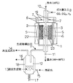
以下、一実施例に基づいて、本発明をさらに詳細に説明する。図1に、本発明を実施するときの反応装置の一例を示す。図1において、1は反応容器であって、たとえば15MPaの圧力に耐え得る金属製たとえばステンレス鋼製の容器である。反応容器1は、この実施例においては図1に示すように、円筒形であり、その横断面中心部に反応容器1と軸心を共有する如く多孔円筒2が配設される。多孔円筒2にはその周壁に多数の孔22が穿設されており、気体はその孔22を通して多孔円筒2壁面を流通できるが、触媒充填層3における触媒は通過できない寸法(直径)とされている。触媒充填層3は、反応容器1内壁面と多孔円筒2外周面間の環状空間であって、トレイ23の上部に形成されている。
Hereinafter, the present invention will be described in more detail based on an example. In FIG. 1, an example of the reaction apparatus when implementing this invention is shown. In FIG. 1, 1 is a reaction vessel, which is a vessel made of metal such as stainless steel that can withstand a pressure of 15 MPa, for example. In this embodiment, the reaction vessel 1 has a cylindrical shape as shown in FIG. 1, and a
4は冷却体であり、この実施例においては、銅製或はステンレス鋼(SUS316)製の冷却管である。冷却体(冷却管)4は多孔円筒内部に配置され、冷却面積を大ならしめるべく螺旋状に形成されている。必要に応じて、冷却面積を拡大するためにフィンを冷却管外周面に形成してもよい。冷却体(冷却管)4内部には、この実施例においては、水が冷媒として流通せしめられる。冷却水(常温)は、反応容器1上部の冷却水入口10から導入され、触媒充填層3において生成したメタノールと冷却体(冷却管)4内壁面において熱交換して昇温し、60℃〜80℃の温水となって冷却水出口11から排出される。この熱交換によって生成メタノールは液化され滴下して反応容器1外に抜き出される。
A cooling body 4 is a cooling pipe made of copper or stainless steel (SUS316) in this embodiment. The cooling body (cooling pipe) 4 is disposed inside the porous cylinder, and is formed in a spiral shape so as to increase the cooling area. If necessary, fins may be formed on the outer peripheral surface of the cooling pipe in order to increase the cooling area. In this embodiment, water is circulated in the cooling body (cooling pipe) 4 as a refrigerant. The cooling water (normal temperature) is introduced from the
5はヒータであって、触媒充填層3における触媒の温度を220℃〜240℃といった温度域まで昇温させるときに用いる。6はフランジであり、反応容器1を気密に保つべくフランジ締結用ボルト孔7にボルトを挿通しナットで緊締する。
19はシール材である。
A
Reference numeral 19 denotes a sealing material.
8は原料ガス導入口であり、ここから水素および酸化炭素を主成分とする原料ガスが反応容器1内上部空間に導入される。9は生成物導出口であって、触媒充填層3で生成し冷却体表面で液化され滴下した液状メタノールおよび未反応ガスからなる気液混合流体が導出される。この気液混合流体はメタノール回収部(気液分離・貯留槽)12内に導入される。メタノール回収部(気液分離・貯留槽)12には、その外周部に冷却ジャケット18が付設されており、その下部の冷却水入口15から冷却水が導入され、上部の冷却水出口16から排出される。メタノール回収部(気液分離・貯留槽)12内の液状メタノール13は、液状メタノール抽出口17から抽出される。14は未反応ガスと気相メタノールの混合気体出口である。
Reference numeral 8 denotes a raw material gas inlet, from which a raw material gas mainly composed of hydrogen and carbon oxide is introduced into the upper space in the reaction vessel 1. Reference numeral 9 denotes a product outlet, from which a gas-liquid mixed fluid composed of liquid methanol and unreacted gas generated in the catalyst packed bed 3 and liquefied and dropped on the surface of the cooling body is led out. This gas-liquid mixed fluid is introduced into a methanol recovery unit (gas-liquid separation / storage tank) 12. The methanol recovery unit (gas-liquid separation / storage tank) 12 has a
図1に示す反応装置を用いて水素および酸化炭素を主成分とする原料ガスからメタノールを合成した。反応容器(外径:37mm、内径:25mm、高さ:160mm)1内に触媒充填層3を形成し内部のガスを合成(原料)ガスに置換した後、常法に従って触媒を活性化し反応を開始した。触媒として市販のメタノール合成触媒(CuO−ZnO−Al2O3):10gを用いた。反応条件は、次の通りである。
合成(原料)ガス流量:200ml/分、圧力:10atm〜40atm(1MPa〜4MPa)、温度:220℃および240℃、合成(原料)ガスの組成:Ar=2.98%、CO=31.09%、CO2=5.05%、H2=残部
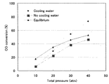
冷却体(冷却管)4における冷却水入口温度=30℃であり、出口温度は冷却水流量(125ml/分程度)により60℃〜80℃の間で変動した。生成物導出口9の気相メタノールをガスクロマトグラフィー分析によってCO、CO2の転化率を算出した。220℃で行った反応における結果を、図2に示す。図2において、横軸は圧力(atm)、縦軸はCO転化率である。圧力:40atm(4MPa)で、冷却体(冷却管)4に冷却水を通した反応におけるメタノールの純度は96.9%であった。
Using the reaction apparatus shown in FIG. 1, methanol was synthesized from a raw material gas mainly composed of hydrogen and carbon oxide. After forming the catalyst packed layer 3 in the reaction vessel (outer diameter: 37 mm, inner diameter: 25 mm, height: 160 mm) 1 and replacing the internal gas with the synthesis (raw material) gas, the catalyst is activated and reacted according to a conventional method. Started. Commercially available methanol synthesis catalyst (CuO—ZnO—Al 2 O 3 ): 10 g was used as a catalyst. The reaction conditions are as follows.
Synthesis (raw material) gas flow rate: 200 ml / min, pressure: 10 atm to 40 atm (1 MPa to 4 MPa), temperature: 220 ° C. and 240 ° C., composition of composition (raw material) gas: Ar = 2.98%, CO = 31.09 %, CO 2 = 5.05%, H 2 = remainder Cooling water inlet temperature in the cooling body (cooling pipe) 4 is 30 ° C., and the outlet temperature is 60 ° C. to 80 ° C. depending on the cooling water flow rate (about 125 ml / min). Fluctuated between. The conversion rate of CO and CO 2 was calculated by gas chromatography analysis of the gas phase methanol at the product outlet 9. The results of the reaction performed at 220 ° C. are shown in FIG. In FIG. 2, the horizontal axis represents pressure (atm) and the vertical axis represents CO conversion. The purity of methanol in the reaction in which cooling water was passed through the cooling body (cooling pipe) 4 at a pressure of 40 atm (4 MPa) was 96.9%.
図2から明らかなように、冷却体(冷却管)4に冷却水を通さない反応(■印)は平衡反応に満たないが、冷却体(冷却管)4に冷却水を通した反応(◆印)は、25atm(2.5MPa)以上の圧力域での反応で平衡転化率を超え、40atm(4MPa)の圧力下の反応では、CO転化率が75%に達している。 As is clear from FIG. 2, the reaction that does not pass cooling water through the cooling body (cooling pipe) 4 (marked by ■) is less than the equilibrium reaction, but the reaction that passes cooling water through the cooling body (cooling pipe) 4 (◆) Indicates the equilibrium conversion rate in the reaction in the pressure range of 25 atm (2.5 MPa) or more, and the CO conversion rate reaches 75% in the reaction under the pressure of 40 atm (4 MPa).
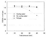
図3に、220℃で行った反応での生成物導出口9におけるCO2とArの比を示す。図3において、横軸は圧力(atm)、縦軸は生成物導出口9におけるCO2とArの比である。図3から明らかなように、冷却体(冷却管)4に冷却水を通さない反応(■印)は平衡反応とほぼ同程度であるが、冷却体(冷却管)4に冷却水を通した反応(◆印)は、圧力:20atm(2MPa)以上の圧力域で、CO2の比率が大きく減少しており、CO2の転化率が向上していることが分かる。 FIG. 3 shows the ratio of CO 2 and Ar at the product outlet 9 in the reaction carried out at 220 ° C. In FIG. 3, the horizontal axis represents pressure (atm), and the vertical axis represents the ratio of CO 2 and Ar in the product outlet 9. As is clear from FIG. 3, the reaction in which the cooling water does not pass through the cooling body (cooling pipe) 4 (marked by ■) is almost the same as the equilibrium reaction, but the cooling water is passed through the cooling body (cooling pipe) 4. In the reaction (marked by ◆), it can be seen that the CO 2 ratio is greatly reduced and the CO 2 conversion rate is improved in the pressure range of 20 atm (2 MPa) or more.
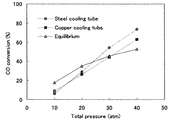
合成(原料)ガス流量:200ml/分、圧力:10atm〜40atm(1MPa〜4MPa)、温度:220℃、冷却体(冷却管)4における冷却水流量:125ml/分、合成(原料)ガスの組成は実施例2におけると同一組成である。この実施例においては、冷却体(冷却管)4の材質を銅およびSUS316としたものについて、合成(原料)ガスからのメタノール合成を行った。その結果を図4に示す。図4に示すように、冷却体(冷却管)4の材質が銅である場合よりもSUS316である場合の方が、高い転化率下にメタノールの合成反応が進行している。 Synthesis (raw material) gas flow rate: 200 ml / min, pressure: 10 atm to 40 atm (1 MPa to 4 MPa), temperature: 220 ° C., cooling water flow rate in cooling body (cooling pipe) 4: 125 ml / min, composition of synthesis (raw material) gas Is the same composition as in Example 2. In this example, methanol was synthesized from synthesis (raw material) gas for the cooling body (cooling pipe) 4 made of copper and SUS316. The result is shown in FIG. As shown in FIG. 4, in the case where the material of the cooling body (cooling pipe) 4 is SUS316, the synthesis reaction of methanol proceeds at a higher conversion rate.
本発明は、天然ガスの改質或は石炭やバイオマスをガス化して得られるガスを原料としてメタノールを製造するプロセスとして好適に用いることができる。また、原料である合成ガスの50%〜70%をメタノールとし、残余の未反応ガスを燃料とする複合システムを構築するときのメタノール合成プロセスとして利用可能である。さらに、小、中規模のメタノール製造プラントとして好適に用いることができる。 The present invention can be suitably used as a process for producing methanol using a gas obtained by reforming natural gas or gasifying coal or biomass as a raw material. Further, it can be used as a methanol synthesis process for constructing a composite system in which 50% to 70% of synthesis gas as a raw material is methanol and the remaining unreacted gas is used as fuel. Furthermore, it can be suitably used as a small and medium-scale methanol production plant.
1 反応容器
2 多孔円筒
3 触媒充填層
4 冷却体(冷却管)
5 ヒータ
6 フランジ
7 ボルト孔
8 原料ガス導入口
9 生成物導出口
10 冷却水入口
11 冷却水出口
12 メタノール回収部(気液分離・貯留槽)
13 液状メタノール
14 未反応ガス+気相メタノール出口
15 冷却水入口
16 冷却水出口
17 液状メタノール抽出口
18 冷却ジャケット
19 シール材
22 孔
23 トレイ
DESCRIPTION OF SYMBOLS 1
5 Heater 6 Flange 7 Bolt hole 8 Source gas inlet 9
13 Liquid methanol 14 Unreacted gas + Gas
Claims (3)
A methanol production apparatus for synthesizing methanol by reacting a raw material gas mainly composed of hydrogen and carbon oxide in the presence of a catalyst, a reaction vessel, and a porous cylinder arranged in one or more in the reaction vessel A catalyst emphasis portion formed between the inner peripheral surface of the reaction vessel and the outer peripheral surface of the porous cylinder, and a cooling surface disposed within the porous cylinder and having a dew point equal to or lower than the dew point of the vapor pressure of generated methanol in the catalyst filling portion. A methanol production apparatus comprising: a cooling body having a refrigerant distribution means; and a methanol recovery unit for extracting and recovering methanol that is liquefied and dropped on the cooling surface of the cooling body from the reaction system.
Priority Applications (1)
| Application Number | Priority Date | Filing Date | Title |
|---|---|---|---|
| JP2004117554A JP4487103B2 (en) | 2004-04-13 | 2004-04-13 | Highly efficient synthesis method of methanol and apparatus therefor |
Applications Claiming Priority (1)
| Application Number | Priority Date | Filing Date | Title |
|---|---|---|---|
| JP2004117554A JP4487103B2 (en) | 2004-04-13 | 2004-04-13 | Highly efficient synthesis method of methanol and apparatus therefor |
Publications (2)
| Publication Number | Publication Date |
|---|---|
| JP2005298413A true JP2005298413A (en) | 2005-10-27 |
| JP4487103B2 JP4487103B2 (en) | 2010-06-23 |
Family
ID=35330394
Family Applications (1)
| Application Number | Title | Priority Date | Filing Date |
|---|---|---|---|
| JP2004117554A Expired - Lifetime JP4487103B2 (en) | 2004-04-13 | 2004-04-13 | Highly efficient synthesis method of methanol and apparatus therefor |
Country Status (1)
| Country | Link |
|---|---|
| JP (1) | JP4487103B2 (en) |
Cited By (7)
| Publication number | Priority date | Publication date | Assignee | Title |
|---|---|---|---|---|
| JP2011515334A (en) * | 2008-02-25 | 2011-05-19 | ハルドール・トプサー・アクチエゼルスカベット | Method and reactor for producing methanol |
| JP2011143370A (en) * | 2010-01-15 | 2011-07-28 | Takuma Co Ltd | Reactor and method for producing reaction product by using the same |
| WO2021060145A1 (en) | 2019-09-27 | 2021-04-01 | 住友化学株式会社 | Chemical reaction method and chemical reaction device |
| JP2021127304A (en) * | 2020-02-12 | 2021-09-02 | 国立大学法人島根大学 | Internally condensed reactor |
| WO2022045328A1 (en) | 2020-08-31 | 2022-03-03 | 住友化学株式会社 | Method for producing methanol |
| WO2022045326A1 (en) | 2020-08-31 | 2022-03-03 | 住友化学株式会社 | Chemical reaction method, chemical reaction apparatus and production method |
| WO2022102210A1 (en) * | 2020-11-13 | 2022-05-19 | 住友化学株式会社 | Methanol production method |
-
2004
- 2004-04-13 JP JP2004117554A patent/JP4487103B2/en not_active Expired - Lifetime
Cited By (14)
| Publication number | Priority date | Publication date | Assignee | Title |
|---|---|---|---|---|
| JP2011515333A (en) * | 2008-02-25 | 2011-05-19 | ハルドール・トプサー・アクチエゼルスカベット | Reactor for methanol production |
| JP2011515334A (en) * | 2008-02-25 | 2011-05-19 | ハルドール・トプサー・アクチエゼルスカベット | Method and reactor for producing methanol |
| JP2011143370A (en) * | 2010-01-15 | 2011-07-28 | Takuma Co Ltd | Reactor and method for producing reaction product by using the same |
| WO2021060145A1 (en) | 2019-09-27 | 2021-04-01 | 住友化学株式会社 | Chemical reaction method and chemical reaction device |
| EP4043424A4 (en) * | 2019-09-27 | 2023-11-15 | Sumitomo Chemical Company, Limited | Chemical reaction method and chemical reaction device |
| CN114423515A (en) * | 2019-09-27 | 2022-04-29 | 住友化学株式会社 | Chemical reaction method and chemical reaction apparatus |
| JP7291350B2 (en) | 2020-02-12 | 2023-06-15 | 国立大学法人島根大学 | internal condensing reactor |
| JP2021127304A (en) * | 2020-02-12 | 2021-09-02 | 国立大学法人島根大学 | Internally condensed reactor |
| WO2022045326A1 (en) | 2020-08-31 | 2022-03-03 | 住友化学株式会社 | Chemical reaction method, chemical reaction apparatus and production method |
| CN115989081A (en) * | 2020-08-31 | 2023-04-18 | 住友化学株式会社 | Chemical reaction method, chemical reaction apparatus, and manufacturing method |
| EP4234521A2 (en) | 2020-08-31 | 2023-08-30 | Sumitomo Chemical Company, Limited | Chemical reaction method, chemical reaction apparatus and production method |
| EP4234521A3 (en) * | 2020-08-31 | 2023-09-27 | Sumitomo Chemical Company, Limited | Chemical reaction method, chemical reaction apparatus and production method |
| WO2022045328A1 (en) | 2020-08-31 | 2022-03-03 | 住友化学株式会社 | Method for producing methanol |
| WO2022102210A1 (en) * | 2020-11-13 | 2022-05-19 | 住友化学株式会社 | Methanol production method |
Also Published As
| Publication number | Publication date |
|---|---|
| JP4487103B2 (en) | 2010-06-23 |
Similar Documents
| Publication | Publication Date | Title |
|---|---|---|
| US8202915B2 (en) | Method and reactor for the preparation of methanol | |
| EP0080270B1 (en) | Synthesis process and reactor | |
| EP3402773B1 (en) | Methanol process | |
| EP1839735B1 (en) | A transverse tubular heat exchange reactor and a process for catalytic synthesis therein | |
| JP5436858B2 (en) | Multistage reactor chemical product production system | |
| EA034987B1 (en) | Process for producing methanol | |
| JP5188895B2 (en) | Methanol synthesis reactor and methanol synthesis method | |
| JP4487103B2 (en) | Highly efficient synthesis method of methanol and apparatus therefor | |
| JP2008532934A (en) | Ethylene oxide plant operation | |
| GB2560784A (en) | Method for revamping a methanol process | |
| JP4427131B2 (en) | Methanol synthesis catalyst equipment | |
| EP1291072B1 (en) | A gas-solid phase exothermic catalytic reactor with low temperature difference and its process | |
| CZ280489B6 (en) | Process for preparing methanol | |
| NZ202746A (en) | Reactor and methanol synthesis process | |
| JP5312355B2 (en) | Reactor and reaction product manufacturing method using the same | |
| JP2011521876A (en) | Cold wall horizontal ammonia converter | |
| WO2021122658A1 (en) | System for methanol production from a synthesis gas rich in hydrogen and co2/co | |
| EP0075056A1 (en) | Synthesis system and process for the production of ammonia | |
| JP7291350B2 (en) | internal condensing reactor | |
| JP4048332B2 (en) | Method for producing hydrogen | |
| JP7319493B2 (en) | Methanol production facility and methanol production method | |
| US10109874B2 (en) | Shift reactor for direct fuel cell hydrogen system | |
| KR20170057072A (en) | Method for producing alcohol from carbon dioxide using slurry reactor | |
| WO2008100170A1 (en) | Methanol producing method and a plant for carrying out said method |
Legal Events
| Date | Code | Title | Description |
|---|---|---|---|
| A621 | Written request for application examination |
Free format text: JAPANESE INTERMEDIATE CODE: A621 Effective date: 20070330 |
|
| A871 | Explanation of circumstances concerning accelerated examination |
Free format text: JAPANESE INTERMEDIATE CODE: A871 Effective date: 20091202 |
|
| A975 | Report on accelerated examination |
Free format text: JAPANESE INTERMEDIATE CODE: A971005 Effective date: 20091211 |
|
| A131 | Notification of reasons for refusal |
Free format text: JAPANESE INTERMEDIATE CODE: A131 Effective date: 20100104 |
|
| A521 | Request for written amendment filed |
Free format text: JAPANESE INTERMEDIATE CODE: A523 Effective date: 20100129 |
|
| TRDD | Decision of grant or rejection written | ||
| A01 | Written decision to grant a patent or to grant a registration (utility model) |
Free format text: JAPANESE INTERMEDIATE CODE: A01 Effective date: 20100225 |
|
| A01 | Written decision to grant a patent or to grant a registration (utility model) |
Free format text: JAPANESE INTERMEDIATE CODE: A01 |
|
| A61 | First payment of annual fees (during grant procedure) |
Free format text: JAPANESE INTERMEDIATE CODE: A61 Effective date: 20100311 |
|
| FPAY | Renewal fee payment (event date is renewal date of database) |
Free format text: PAYMENT UNTIL: 20130409 Year of fee payment: 3 |
|
| R150 | Certificate of patent or registration of utility model |
Ref document number: 4487103 Country of ref document: JP Free format text: JAPANESE INTERMEDIATE CODE: R150 Free format text: JAPANESE INTERMEDIATE CODE: R150 |
|
| S533 | Written request for registration of change of name |
Free format text: JAPANESE INTERMEDIATE CODE: R313533 |
|
| FPAY | Renewal fee payment (event date is renewal date of database) |
Free format text: PAYMENT UNTIL: 20130409 Year of fee payment: 3 |
|
| R350 | Written notification of registration of transfer |
Free format text: JAPANESE INTERMEDIATE CODE: R350 |
|
| FPAY | Renewal fee payment (event date is renewal date of database) |
Free format text: PAYMENT UNTIL: 20130409 Year of fee payment: 3 |
|
| R250 | Receipt of annual fees |
Free format text: JAPANESE INTERMEDIATE CODE: R250 |
|
| R250 | Receipt of annual fees |
Free format text: JAPANESE INTERMEDIATE CODE: R250 |
|
| R250 | Receipt of annual fees |
Free format text: JAPANESE INTERMEDIATE CODE: R250 |
|
| R250 | Receipt of annual fees |
Free format text: JAPANESE INTERMEDIATE CODE: R250 |
|
| R250 | Receipt of annual fees |
Free format text: JAPANESE INTERMEDIATE CODE: R250 |
|
| R250 | Receipt of annual fees |
Free format text: JAPANESE INTERMEDIATE CODE: R250 |
|
| R250 | Receipt of annual fees |
Free format text: JAPANESE INTERMEDIATE CODE: R250 |
|
| R250 | Receipt of annual fees |
Free format text: JAPANESE INTERMEDIATE CODE: R250 |
|
| R250 | Receipt of annual fees |
Free format text: JAPANESE INTERMEDIATE CODE: R250 |
|
| R250 | Receipt of annual fees |
Free format text: JAPANESE INTERMEDIATE CODE: R250 |