JP2005298097A - Food conveying device - Google Patents
Food conveying device Download PDFInfo
- Publication number
- JP2005298097A JP2005298097A JP2004114133A JP2004114133A JP2005298097A JP 2005298097 A JP2005298097 A JP 2005298097A JP 2004114133 A JP2004114133 A JP 2004114133A JP 2004114133 A JP2004114133 A JP 2004114133A JP 2005298097 A JP2005298097 A JP 2005298097A
- Authority
- JP
- Japan
- Prior art keywords
- food
- force
- belt conveyor
- endless conveyor
- upper endless
- Prior art date
- Legal status (The legal status is an assumption and is not a legal conclusion. Google has not performed a legal analysis and makes no representation as to the accuracy of the status listed.)
- Pending
Links
- 235000013305 food Nutrition 0.000 title claims abstract description 182
- 238000003825 pressing Methods 0.000 claims description 22
- 230000008602 contraction Effects 0.000 description 3
- 230000005484 gravity Effects 0.000 description 2
- 235000021059 hard food Nutrition 0.000 description 2
- 230000001133 acceleration Effects 0.000 description 1
- 238000001035 drying Methods 0.000 description 1
- 230000000694 effects Effects 0.000 description 1
- 230000005489 elastic deformation Effects 0.000 description 1
- 238000000034 method Methods 0.000 description 1
- 230000000149 penetrating effect Effects 0.000 description 1
- 238000005096 rolling process Methods 0.000 description 1
- 235000021058 soft food Nutrition 0.000 description 1
- 230000001360 synchronised effect Effects 0.000 description 1
- 235000019640 taste Nutrition 0.000 description 1
- 235000019583 umami taste Nutrition 0.000 description 1
Images
Landscapes
- Details Of Cutting Devices (AREA)
- Structure Of Belt Conveyors (AREA)
Abstract
Description
本発明は、下側無端コンベヤと上側無端コンベヤとの間に食品を挟んで裁断装置等の所定位置まで搬送する食品搬送装置に関するものである。 The present invention relates to a food conveying apparatus that conveys food between a lower endless conveyor and an upper endless conveyor to a predetermined position such as a cutting apparatus.
食品販売業者等が食品を需要者に供給するに際し、食品販売業者等は食品を需要者にとって利用しやすい形状に裁断して需要者の便宜を図ることが多い。近年、食品販売業者等は大量の食品を取り扱うようになってきており、食品の裁断量の増加に伴って、裁断作業の効率化を求めている。このため、食品販売業者等は食品の搬送及び裁断を自動化し、作業の迅速化や低コスト化等を図っている(例えば、特許文献1を参照)。 When a food seller or the like supplies food to a consumer, the food seller or the like often cuts the food into a shape that can be easily used by the consumer to improve the convenience of the consumer. In recent years, food dealers and the like have come to handle a large amount of food, and as the amount of food cut increases, the efficiency of cutting work is demanded. For this reason, food dealers and the like automate the conveyance and cutting of food to speed up operations and reduce costs (for example, see Patent Document 1).
食品を食品裁断装置まで搬送するために用いられる食品搬送装置は、下側ベルトコンベヤと上側ベルトコンベヤを備え、下側ベルトコンベヤと上側ベルトコンベヤとの間に搬送される食品を挟持する。そして、下側ベルトコンベヤと上側ベルトコンベヤとの間に搬送される食品を挟持したまま、食品裁断装置によって食品を裁断する。
食品裁断装置が下側ベルトコンベヤと上側ベルトコンベヤとの間に挟持された食品を裁断する際、食品を挟持する力が弱いと、食品裁断装置において食品の位置が安定せず、食品を見栄え良く裁断できず、食品の裁断面が荒れたものとなりやすい。食品の裁断面が荒れていると、裁断面から食品の旨み成分等が流れ出しやすく、裁断面の乾燥も速くなり、短時間で食品の食味が低下し、食品販売業者等は高品質の食品を提供できなくなってしまう。
A food conveyance device used to convey food to a food cutting device includes a lower belt conveyor and an upper belt conveyor, and sandwiches food conveyed between the lower belt conveyor and the upper belt conveyor. Then, the food is cut by the food cutting device while sandwiching the food conveyed between the lower belt conveyor and the upper belt conveyor.
When the food cutting device cuts the food sandwiched between the lower belt conveyor and the upper belt conveyor, if the force to pinch the food is weak, the position of the food is not stable in the food cutting device and the food looks good It cannot be cut, and the cut surface of the food tends to be rough. If the cut surface of the food is rough, the umami component of the food tends to flow out from the cut surface, the drying of the cut surface will be faster, the taste of the food will be reduced in a short time, and food distributors will produce high quality food It can no longer be provided.
このため、スプリングを用いて下側ベルトコンベヤと上側ベルトコンベヤのうち、一方のベルトコンベヤを他方のベルトコンベヤに向けて押圧し、スプリングの弾性力によって下側ベルトコンベヤと上側ベルトコンベヤとに食品を挟持する力を与える。
しかしながら、従来の食品搬送装置においては、下側ベルトコンベヤと上側ベルトコンベヤとが食品を挟持する力の大きさを、食品の種類に応じて適切なものとすることが困難であった。
例えば、硬い食品を食品裁断装置が裁断する際、下側ベルトコンベヤと上側ベルトコンベヤとが食品をしっかりと挟持していなければ、食品裁断装置の刃物から加わる力によって食品が転がる等し、食品の位置が安定せず、食品の裁断面が荒れてしまう。また、食品裁断装置の刃物が、位置の安定していない硬い食品を裁断すると、刃物の刃先が損傷しやすく、損傷した刃物を使用することが裁断面を荒らす原因となる。
However, in the conventional food conveyance device, it has been difficult to make the magnitude of the force with which the lower belt conveyor and the upper belt conveyor pinch the food appropriately according to the type of food.
For example, when the food cutting device cuts hard food, if the lower belt conveyor and the upper belt conveyor do not hold the food firmly, the food rolls due to the force applied from the blade of the food cutting device, etc. The position is not stable, and the cut surface of the food becomes rough. Moreover, when the cutting tool of the food cutting apparatus cuts hard food whose position is not stable, the cutting edge of the cutting tool is easily damaged, and the use of the damaged cutting tool causes rough cutting.
柔らかい食品を食品裁断装置が裁断する際、下側ベルトコンベヤと上側ベルトコンベヤとが食品を挟持する力が強すぎると、食品が押しつぶされ、やはり、食品の裁断面が荒れてしまう。
本発明は、上記した従来の技術の問題点を除くためになされたものであり、その目的とするところは、適切な大きさの力で食品を挟持したまま、食品を食品裁断装置まで搬送可能な食品搬送装置を提供することである。
When the food cutting device cuts soft food, if the force of the lower belt conveyor and the upper belt conveyor to pinch the food is too strong, the food is crushed and the cut surface of the food is also roughened.
The present invention has been made in order to eliminate the above-described problems of the prior art, and the object of the present invention is to allow food to be conveyed to a food cutting device while holding the food with an appropriate magnitude of force. Is to provide a simple food transport device.
本発明はその課題を解決するために以下のような構成をとる。請求項1の発明に係る食品搬送装置は、下側無端コンベヤと上側無端コンベヤとの間に食品を挟持して搬送する食品搬送装置であって、上下動可能に支承された上側無端コンベヤに調整可能な大きさの押下力を与える押下機構と、上側無端コンベヤに前記押下力以下の大きさの押上力を与える押上機構と、を有する。 The present invention has the following configuration in order to solve the problem. The food conveyance device according to the invention of claim 1 is a food conveyance device for nipping and conveying food between a lower endless conveyor and an upper endless conveyor, and is adjusted to an upper endless conveyor supported so as to be vertically movable. A pressing mechanism that applies a pressing force of a possible magnitude; and a lifting mechanism that applies a lifting force equal to or smaller than the pressing force to the upper endless conveyor.
請求項1の発明によると、上下動可能に支承された上側無端コンベヤに、押下力が押下機構から与えられ、押上力が押上機構から与えられ、押下力と押上力との差が、下側無端コンベヤと上側無端コンベヤとの間に食品を挟持する力となる。押下力を調整することによって、下側無端コンベヤと上側無端コンベヤとの間に挟持された食品に働く力の大きさを調整できる。
なお、上側無端コンベヤとして、例えば、ゴム製ベルトや帆布製ベルトが無限循環するベルトコンベヤ等を挙げることができる。また、下側無端コンベヤとして、例えば、ゴム製ベルトや帆布製ベルトが無限循環するベルトコンベヤ、ベルト状に連なる多数の板状部材が無限循環するベルトコンベヤ、ローラコンベヤ等を挙げることができる。
According to the first aspect of the present invention, the pressing force is applied from the pressing mechanism to the upper endless conveyor supported so as to move up and down, the lifting force is applied from the lifting mechanism, and the difference between the pressing force and the lifting force is It becomes the force which pinches | interposes a foodstuff between an endless conveyor and an upper endless conveyor. By adjusting the pressing force, the magnitude of the force acting on the food sandwiched between the lower endless conveyor and the upper endless conveyor can be adjusted.
Examples of the upper endless conveyor include a belt conveyor in which a rubber belt or a canvas belt circulates infinitely. Examples of the lower endless conveyor include a belt conveyor in which a rubber belt and a canvas belt are circulated infinitely, a belt conveyor in which a large number of plate-like members are circulated infinitely, and a roller conveyor.
請求項2の発明に係る食品搬送装置は、請求項1に記載の食品搬送装置であって、前記押上機構が上側無端コンベヤに与える押上力を調整可能に構成されている。
請求項2の発明によると、押上力を調整することによっても、下側無端コンベヤと上側無端コンベヤとの間に挟持された食品に働く力の大きさを調整できる。
A food conveying device according to a second aspect of the present invention is the food conveying device according to the first aspect, wherein the lifting force applied to the upper endless conveyor by the lifting mechanism is adjustable.
According to the invention of claim 2, the magnitude of the force acting on the food sandwiched between the lower endless conveyor and the upper endless conveyor can also be adjusted by adjusting the push-up force.
請求項3の発明に係る食品搬送装置は、請求項1又は請求項2に記載の食品搬送装置であって、作用点から上側無端コンベヤに押下力を与えて支点回りに回動可能な腕部と、当該腕部の長手方向に移動して当該支点との距離を調整可能な錘と、を前記押下機構が有する。
請求項3の発明によると、錘を腕部の長手方向に移動させることによって、錘の位置と腕部の支点との間の距離を調整することができ、作用点から上側無端コンベヤに働く押下力の大きさを調整することができる。
A food conveying device according to a third aspect of the present invention is the food conveying device according to the first or second aspect, wherein the arm portion is rotatable around a fulcrum by applying a pressing force to the upper endless conveyor from the operating point. And a weight capable of moving in the longitudinal direction of the arm portion and adjusting a distance from the fulcrum, the pressing mechanism.
According to the invention of claim 3, by moving the weight in the longitudinal direction of the arm portion, the distance between the position of the weight and the fulcrum of the arm portion can be adjusted, and the press acting on the upper endless conveyor from the action point The magnitude of the force can be adjusted.
請求項4の発明に係る食品搬送装置は、請求項3に記載の食品搬送装置であって、前記支点で基礎フレームと前記腕部とを接続してそれぞれ回動可能な複数の第1の関節部と、上側無端コンベヤと腕部の前記作用点とを接続して前記基礎フレームに形成された案内路を摺動可能な主軸と、前記作用点で当該主軸と腕部とを接続する回動可能な第2の関節部と、を有する。
請求項4の発明によると、腕部の支点が複数の第1の関節部を有し、各第1の関節部が回動可能となっているので、腕部が支点回りを回動すると、第1の関節部がそれぞれ動き、腕部の作用点が主軸の直上に維持され、第2の関節部が回動して主軸と腕部とのなす角度が変化し、腕部の回動が主軸の上下動に変換され、主軸が基礎フレームに形成された案内路内を摺動し、主軸から上側無端コンベヤへ押下力が伝わる。
A food conveyance device according to a fourth aspect of the present invention is the food conveyance device according to the third aspect, wherein a plurality of first joints that are respectively rotatable by connecting the base frame and the arm portion at the fulcrum. A main shaft that is slidable on a guide path formed on the base frame by connecting the upper endless upper conveyor and the action point of the arm portion, and turning that connects the main shaft and the arm portion at the action point A possible second joint.
According to the invention of claim 4, since the fulcrum of the arm portion has a plurality of first joint portions, and each first joint portion is rotatable, when the arm portion rotates around the fulcrum, The first joint part moves, the action point of the arm part is maintained immediately above the main axis, the second joint part rotates, the angle between the main axis and the arm part changes, and the arm part rotates. It is converted into the vertical movement of the main shaft, the main shaft slides in the guide path formed in the base frame, and the pressing force is transmitted from the main shaft to the upper endless conveyor.
請求項5の発明に係る食品搬送装置は、請求項3又は請求項4に記載の食品搬送装置であって、上側無端コンベヤを上下方向に案内する案内軸に装着されて上側無端コンベヤに押上力を与える弾性体を、前記押上機構が有する。
請求項5の発明によると、案内軸に案内されて上側無端コンベヤが上下に動き、下側無端コンベヤと上側無端コンベヤとの間に食品が挟持される。押上力が案内軸に装着された弾性体から上側無端コンベヤに働く。案内軸に装着された弾性体の弾性係数を調整することによって、押上機構から上側無端コンベヤに働く押上力の大きさを調整できる。
なお、案内軸に装着する弾性体として、例えば、コイルスプリングを挙げることができる。下側無端コンベヤと上側無端コンベヤとの間に挟持される食品の厚さが変動しても、このコイルスプリングが弾性変形し、食品の厚さの変動に反応して上側無端コンベヤが上下に動く。
A food conveying device according to a fifth aspect of the present invention is the food conveying device according to the third or fourth aspect, wherein the food conveying device is mounted on a guide shaft that guides the upper endless conveyor in the vertical direction and is pushed up by the upper endless conveyor. The push-up mechanism has an elastic body that gives
According to the invention of claim 5, the upper endless conveyor moves up and down as guided by the guide shaft, and the food is sandwiched between the lower endless conveyor and the upper endless conveyor. The lifting force acts on the upper endless conveyor from the elastic body mounted on the guide shaft. By adjusting the elastic coefficient of the elastic body mounted on the guide shaft, it is possible to adjust the magnitude of the lifting force that acts on the upper endless conveyor from the lifting mechanism.
An example of the elastic body attached to the guide shaft is a coil spring. Even if the thickness of the food sandwiched between the lower endless conveyor and the upper endless conveyor fluctuates, this coil spring elastically deforms and the upper endless conveyor moves up and down in response to the change in the thickness of the food. .
請求項6の発明に係る食品搬送装置は、請求項3から請求項5のいずれかに記載の食品裁断機であって、前記主軸に装着されて上側無端コンベヤに押上力を与える弾性体を、前記押上機構が有する。
請求項6の発明によると、主軸に装着された弾性体から上側無端コンベヤに、上側無端コンベヤを上方に引き上げる力が押上力の一部として働く。押上力の一部分が主軸に装着された弾性体から働いているので、案内軸に装着された弾性体の弾性係数を小さくすることができる。案内軸に装着された弾性体の弾性係数を小さくすると、この弾性体の伸縮量が大きくなり、下側無端コンベヤと上側無端コンベヤとの間に挟持される食品の厚さの変動に対して、上側無端コンベヤが敏感且つ迅速に反応して上下に動く。
なお、主軸に装着する弾性体として、例えば、コイルスプリングを挙げることができる。腕部が急に下降して腕部から上側無端コンベヤへ押下力が急激に働くことは、このコイルスプリングの弾性変形により防止され、食品が下側無端コンベヤと上側無端コンベヤとの間で押しつぶされることが防止される。
A food conveying device according to a sixth aspect of the present invention is the food cutting machine according to any one of the third to fifth aspects, wherein an elastic body that is attached to the main shaft and applies an upward force to the upper endless conveyor, The push-up mechanism has.
According to invention of Claim 6, the force which pulls up an upper endless conveyor from an elastic body with which the main shaft was mounted | worn works as a part of pushing-up force. Since a part of the push-up force works from the elastic body mounted on the main shaft, the elastic coefficient of the elastic body mounted on the guide shaft can be reduced. When the elastic coefficient of the elastic body mounted on the guide shaft is reduced, the amount of expansion and contraction of this elastic body increases, and for the variation in the thickness of the food sandwiched between the lower endless conveyor and the upper endless conveyor, The upper endless conveyor responds sensitively and quickly and moves up and down.
An example of the elastic body attached to the main shaft is a coil spring. It is prevented by the elastic deformation of this coil spring that the arm part suddenly descends and the pressing force acts from the arm part to the upper endless conveyor, and the food is crushed between the lower endless conveyor and the upper endless conveyor. It is prevented.
請求項7の発明に係る食品搬送装置は、請求項5又は請求項6に記載の食品裁断機であって、上側無端コンベヤを上方に引き上げるバランス部を、前記押上機構が有する。
請求項7の発明によると、バランス部から上側無端コンベヤに、上側無端コンベヤを上方に引き上げる力が押上力の一部として働く。押上力の一部分がバランス部から働いているので、案内軸に装着された弾性体の弾性係数を小さくすることができる。案内軸に装着された弾性体の弾性係数を小さくすると、この弾性体の伸縮量が大きくなり、下側無端コンベヤと上側無端コンベヤとの間に挟持される食品の厚さの変動に対して、上側無端コンベヤが敏感且つ迅速に反応して上下に動く。
なお、例えば、バランス部をバランス錘により構成し、バランス錘の質量によって上側無端コンベヤに引き上げる力を与えることができる。また、バランス部を、例えば、コイルスプリング等の弾性体により構成し、この弾性体の弾性力によって上側無端コンベヤに引き上げる力を与えることもできる。
A food conveying device according to a seventh aspect of the present invention is the food cutting machine according to the fifth or sixth aspect, wherein the push-up mechanism has a balance portion that pulls the upper endless conveyor upward.
According to invention of Claim 7, the force which pulls up an upper endless conveyor from a balance part to an upper endless conveyor acts as a part of pushing-up force. Since a part of the lifting force works from the balance portion, the elastic coefficient of the elastic body attached to the guide shaft can be reduced. When the elastic coefficient of the elastic body mounted on the guide shaft is reduced, the amount of expansion and contraction of this elastic body increases, and for the variation in the thickness of the food sandwiched between the lower endless conveyor and the upper endless conveyor, The upper endless conveyor responds sensitively and quickly and moves up and down.
In addition, for example, the balance part can be constituted by a balance weight, and the force to be pulled up to the upper endless conveyor can be given by the mass of the balance weight. Moreover, a balance part can be comprised by elastic bodies, such as a coil spring, for example, and can also give the force pulled up to an upper endless conveyor with the elastic force of this elastic body.
本発明は、上記のような食品搬送措置であるので、適切な大きさの力で食品を挟持したまま、食品を食品裁断装置まで搬送可能な食品搬送装置を提供できるという効果がある。 Since the present invention is a food conveyance measure as described above, there is an effect that it is possible to provide a food conveyance device capable of conveying food to a food cutting device while holding the food with an appropriate magnitude of force.
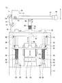
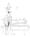
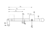
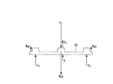
本発明を実施するための最良の形態を図1及び図2を参照しつつ説明する。図1は本発明に係る食品裁断機の正面図、図2は本発明に係る食品裁断機の一部分を破断して示す側面図、図3はリンク腕及び腕部における回転モーメントの説明図、図4は支承体における力のつりあいの説明図である。
食品搬送装置10は基礎フレーム12を有し、基礎フレーム12の上部に下側ベルトコンベヤ14が下側無端コンベヤとして設置されている。下側ベルトコンベヤ14は、ゴム製ベルトが無限循環する公知のベルトコンベヤであり、調整可能な所定の間隔(ピッチ)で間歇的に回動して下側ベルトコンベヤ14上の食品を搬送可能に構成されている。
The best mode for carrying out the present invention will be described with reference to FIGS. FIG. 1 is a front view of a food cutting machine according to the present invention, FIG. 2 is a side view showing a part of the food cutting machine according to the present invention, and FIG. 3 is an explanatory view of rotational moments in a link arm and an arm part. 4 is an explanatory view of force balance in the support body.
The
基礎フレーム12は、左右の縦枠20と上枠22とからなる門形の枠体18を上部に有し、枠体18内に左右2本の案内軸24が立設されており、左右2本の案内軸24の間に、下側ベルトコンベヤ14の前端部分が位置している。
各案内軸24にはリング状部材がカラー26として嵌っており、固定用螺子68によってカラー26は任意の高さで案内軸24に固定可能となっている。カラー26の上には、弾性体である主コイルスプリング30が載っており、主コイルスプリング30を案内軸24が貫通している。この主コイルスプリング30が押上機構の一部をなしている。主コイルスプリング30を貫通した案内軸24は、更に、板状部材である支承体32の左右の案内孔34を貫通しており、支承体32が左右の案内軸24の主コイルスプリング30の上に載っている。
The
A ring-shaped member is fitted to each
支承体32の左右両側には、枠体18の左右の縦枠20に装着された滑車36を介して、分銅38がバランス錘として懸下されている。この分銅38が押上機構の一部をなしている。
支承体32の下側には、後述の上側ベルトコンベヤ16が、支承体32に固定されたブラケット32aと、このブラケット32aに固定された上側ベルトコンベヤ16のフレーム16aとを介して支承されている。支承体32の上側中央には主軸40が立設されており、主軸40が枠体18の上枠22の主軸孔42内を上下に摺動可能に貫通している。この主軸孔42が主軸40の案内路をなしている。主軸孔42から上方に突出する主軸40の先端部分は大径部となっており、この大径部の下部に段部46が形成されている。
On the lower side of the
支承体32に懸下されて支承されている上側ベルトコンベヤ16は、はゴム製ベルトが無限循環する公知のベルトコンベヤであり、上側無端コンベヤをなす。上側ベルトコンベヤ16の前端部分が左右2本の案内軸24の間に位置し、上側ベルトコンベヤ16の前端部分と下側ベルトコンベヤ14との間に食品を挟持可能に構成されている。また、上側ベルトコンベヤ16は、下側ベルトコンベヤ14と同期して所定の間隔(ピッチ)で間歇的に回動可能に構成されている。
The
枠体18の上枠22の左端側(図1において左側)には、支柱48が立設されており、支柱48の先端がリンク腕50の一端にピン止めされて関節54をなし、関節54において支柱48の先端回りをリンク腕50が回動可能に構成されている。棒状部材からなり押下機構の一部をなす腕部52の一端がリンク腕50の他端にピン止めされて関節56をなし、関節56においてリンク腕50のこの他端回りを腕部52が回動可能に構成されている。関節54と関節56とが第1の関節部をなしている。
A
腕部52の中間部分が、上枠22の主軸孔42から突出する主軸40の先端にピン止めされて関節58をなし、関節58において主軸40の先端回りを腕部52が回動可能に構成されている。関節58が第2の関節部をなしている。
上枠22の主軸孔42から上方に突出する主軸40が、弾性体である補助コイルスプリング62及び座金64を貫通しており、上枠22の上に補助コイルスプリング62が載り、補助コイルスプリング62の上に座金64が載っている。この補助コイルスプリング62が押上機構の一部をなしている。補助コイルスプリング62の長さは、主軸孔42内を上下に摺動する主軸40の摺動部分の長さよりも短く、主軸40が主軸孔42内を下降すると、主軸40の段部46が座金64の上に載り、主軸40が主軸孔42内を上昇すると、主軸40の段部46が座金64から離れる構成となっている。
An intermediate portion of the
The
関節56と反対側の腕部52の端部にはハンドル60が形成されており、腕部52上に、押下機構の一部をなす錘66が関節56とハンドル60との間をスライド可能に載っており、錘66は固定用螺子70によって関節56とハンドル60との間の任意の位置で固定可能に構成されている。
そして、主コイルスプリング30、分銅38及び補助コイルスプリング62が押上機構を構成している。また、上側ベルトコンベヤ16、フレーム16a、ブラケット32aを含む支承体32、主軸40、腕部52及び錘66と、これらの付属品が、これらの荷重によって上側ベルトコンベヤ16を押し下げる作用があるので、押下機構を構成している。
A
The
食品搬送装置10に隣接して食品裁断装置72が設置されており、食品裁断装置72は上下動する刃物74を有し、上下動する刃物74によって食品搬送装置10から搬送されてくる食品を裁断可能に構成されている。刃物74の上下動方向は、下側ベルトコンベヤ14の上側の搬送面に対して直交している。上側ベルトコンベヤ16側の刃物74の裏面と上側ベルトコンベヤ16の前端とは互いに近接している。例えば、刃物74の上側ベルトコンベヤ16側の裏面と上側ベルトコンベヤ16の前端との距離は0.5mmである。また、刃物74は、所定の間隔で間歇的に回動する下側ベルトコンベヤ14と同期して、下側ベルトコンベヤ14の間歇的な停止時に下降し且つ上昇するように、所定の時間間隔で上下動可能に構成されている。なお、図1においては、食品裁断装置72の図示を省略している。
A
以上において、図1に示されるように、錘66が腕部52の左端部(関節56に最も近い位置)にあるときに、上側ベルトコンベヤ16が下側ベルトコンベヤ14と所定間隔をあけて浮いた状態となるように、腕部52、錘66、主軸40、支承体32、上側ベルトコンベヤ16その他の上側ベルトコンベヤ16を降下させようとする荷重(押下力)と、この荷重に対抗する主コイルスプリング30、分銅38、補助コイルスプリング62による押上力とをバランスさせてある。この状態では、下側ベルトコンベヤ14上の食品に上側ベルトコンベヤ16による押圧力は負荷されない。この押圧力を調整するための一方法は、錘66を前記位置から図1における右方にスライドさせることである。
In the above, as shown in FIG. 1, when the
本実施の形態は上記のように構成されており、次に、その作用について説明する。
まず、食品搬送装置10により食品裁断装置72まで搬送する食品の種類に応じて、下側ベルトコンベヤ14と上側ベルトコンベヤ16との間に食品を挟持するために必要な大きさの力Fを定める。例えば、食品が柔らかいものである場合、この食品を押しつぶすことなく、下側ベルトコンベヤ14と上側ベルトコンベヤ16の間で食品を挟持するに足りる大きさの力Fを定める。
The present embodiment is configured as described above, and the operation thereof will be described next.
First, a force F of a magnitude necessary for sandwiching food between the
また、食品が硬いものである場合、下側ベルトコンベヤ14と上側ベルトコンベヤ16の間で挟持されている食品に、食品裁断装置72の刃物74から裁断力が働いても、食品が移動や姿勢を崩すことのない力Fを定める。
力Fを定めたら、錘66を腕部52上で後述する位置にスライドさせ、関節58を作用点として主軸40を介して錘66から上側ベルトコンベヤ16に力Fを加える。支柱48の先端の関節54においてリンク腕50が回動し、リンク腕50の一端の関節56において腕部52が回動して、腕部52における関節58が常に枠体18の上枠22の主軸孔42の直上に位置している。腕部52が回動すると、関節58において腕部52と主軸40がなす角度が変化して、主軸40は主軸孔42内を常に上下に摺動可能となっており、腕部52と主軸40がなす角度にかかわらず、力Fが常に主軸40から上側ベルトコンベヤ16に働く。
Further, when the food is hard, the food is moved or placed even if the cutting force of the
When the force F is determined, the
なお、錘66が腕部52の左端部(関節56に最も近い位置)にあるとき、上側ベルトコンベヤ16が下側ベルトコンベヤ14と所定間隔をあけて浮いた状態となっており、力Fの大きさは零である。したがって、このとき、下側ベルトコンベヤ14と上側ベルトコンベヤ16の間において、食品の上面が上側ベルトコンベヤ16と接触するだけであり、食品には上側ベルトコンベヤ16から負荷が働かない。錘66が腕部52の左端部から図1の右方へスライドすると、錘66のスライド量に応じて力Fが大きくなり、下側ベルトコンベヤ14と上側ベルトコンベヤ16との間において、食品を挟持する力が大きくなる。
When the
腕部52上における錘66の位置は以下のようにして求められる。
いま、関節54回りの回転モーメントを考えると次式(1)式が成立し(図3を参照)、支承体32に働く力のつりあいを考えると次式(2)が成立する(図4を参照)。
F1L1−W1gL2−W2gL3=0 ・・・(1)
F1+W3g−F−2F2−F3−2W4g=0 ・・・(2)
The position of the
Now, considering the rotational moment around the joint 54, the following equation (1) is established (see FIG. 3), and considering the balance of forces acting on the
F 1 L 1 −W 1 gL 2 −W 2 gL 3 = 0 (1)
F 1 + W 3 g-F -2F 2 -F 3 -2W 4 g = 0 ··· (2)
ただし、L1:主軸40と関節54との間の水平距離
L2:錘66と関節54との間の水平距離
L3:リンク腕50及び腕部52の重心と関節54との間の水平距離
W1:錘66の質量
W2:リンク腕50及び腕部52の合計質量
W3:上側ベルトコンベヤ16、主軸40、支承体32、フレーム16a及びブラケット32aの合計質量
W4:分銅38の質量
F:下側ベルトコンベヤ14と上側ベルトコンベヤ16との間に食品を挟持する力
F1:主軸40と腕部52との間に働く力
F2:主コイルスプリング30から支承体32に働く押上力
F3:補助コイルスプリング62から支承体32に働く押上力
g:重力加速度
L 1 : horizontal distance between the
L 2 : Horizontal distance between the
L 3 : Horizontal distance between the center of gravity of the
W 1 : Mass of the
W 2 : Total mass of the
W 3 : Total mass of the
W 4 : Mass of the
F: Force for sandwiching food between the
F 1 : force acting between the
F 2 : Pushing force acting on the
F 3 : Pushing force acting on the
g: Gravity acceleration
式(1)及び式(2)より関節54と錘66との間の水平距離L2は次式(3)によって表される。
L2=(FL1+2F2L1+F3L1+2W4gL1−W3gL1+W2gL3)/(W1g) ・・・(3)
式(3)によって求められた位置まで、錘66を腕部52上でスライドさせ、錘66を固定用螺子70によって固定する。これによって、食品に対する上側ベルトコンベヤ16の押圧力は最適の状態に設定される。
From the equations (1) and (2), the horizontal distance L 2 between the joint 54 and the
L 2 = (FL 1 + 2F 2 L 1 + F 3 L 1 + 2W 4 gL 1 −W 3 gL 1 + W 2 gL 3 ) / (W 1 g) (3)
The
錘66を腕部52に固定したら、下側ベルトコンベヤ14と上側ベルトコンベヤ16とを所定の間隔で間歇的に回動させ、同じ所定の間隔で食品裁断装置72の刃物74を上下動させ、食品を下側ベルトコンベヤ14の上に載せる。
食品が下側ベルトコンベヤ14によって食品裁断装置72へ向かって搬送され、食品裁断装置72の手前において、食品が下側ベルトコンベヤ14と上側ベルトコンベヤ16との間に力Fで挟持される。そして、下側ベルトコンベヤ14と上側ベルトコンベヤ16との間に挟持された食品が、所定の間隔で一定距離ずつ食品裁断装置72に向かって進み、食品裁断装置72に達し、食品裁断装置72の刃物74が食品を裁断する。刃物74が下側ベルトコンベヤ14及び上側ベルトコンベヤ16の回動間隔と同期して上下動しているので、裁断される食品の厚さは一定の厚さとなっている。
When the
The food is conveyed toward the
また、上側ベルトコンベヤ16側の刃物74の裏面と上側ベルトコンベヤ16の前端とは互いに近接して0.5mmしか離れていないので、刃物74により裁断された食品が上側ベルトコンベヤ16から剥離されるから、裁断された食品が上側ベルトコンベヤ16に付着したまま循環されることが防止されている。かかる理由から、上側ベルトコンベヤ16と刃物74との間隔は裁断される食品の厚さよりも小さいことが好ましい。また、この間隔が小さいほど、裁断される食品を小さな力で確実に押えることができる。
In addition, since the back surface of the
なお、下側ベルトコンベヤ14と上側ベルトコンベヤ16とが食品を挟持する力Fは、腕部52上における錘66の位置を変化させること、すなわち、関節54と錘66との間の水平距離L2を変化させることによって調整できるが、錘66の質量W1、分銅38の質量W4、補助コイルスプリング62の弾性係数、主コイルスプリング30の弾性係数を変えることによっても調整できる。
The force F with which the
例えば、食品が柔らかいものである場合、L2を小さくすることにより、すなわち、錘66を左端部の関節56に最も近い位置までスライドさせることにより、力Fを零まで小さくすることができ、下側ベルトコンベヤ14と上側ベルトコンベヤ16との間に挟持された食品が力Fによって押しつぶされる等することを防止できる。また、食品が硬いものである場合、L2を大きくすることにより、すなわち、錘66を図1の右方へスライドさせることにより、力Fを大きくすることができ、下側ベルトコンベヤ14と上側ベルトコンベヤ16との間に挟持された食品が転がる等することを防止できる。
For example, if the food is soft, the force F can be reduced to zero by reducing L 2 , that is, by sliding the
下側ベルトコンベヤ14と上側ベルトコンベヤ16とが、食品の種類や性状に応じた大きさの力F、つまり、裁断時に食品の移動や姿勢変化を防止するために必要な最低の押え力で食品を挟持し、力Fで挟持された食品を食品裁断装置72の刃物74が裁断するので、食品の裁断面が荒れることが防止され、食品裁断装置72の刃物74が損傷することも防止されている。
The
下側ベルトコンベヤ14と上側ベルトコンベヤ16とによって挟持されている食品の厚さが変動する場合、主コイルスプリング30及び補助コイルスプリング62が伸縮し、支承体32が上下動し、上側ベルトコンベヤ16も上下動する。主コイルスプリング30及び補助コイルスプリング62の各弾性係数を変化させることによって、食品の厚さの変動に追従する上側ベルトコンベヤ16の上下動の速度を調整できる。
When the thickness of food sandwiched between the
すなわち、主コイルスプリング30及び補助コイルスプリング62の各弾性係数を小さくした場合、食品の厚さが変動して、食品から上側ベルトコンベヤ16に働く反力の大きさが変化すると、主コイルスプリング30及び補助コイルスプリング62における伸縮量の変化が大きくなり、食品の厚さの変動に対して、上側ベルトコンベヤ16はその高さを迅速且つ敏感に上下に変化させることができる。
That is, when the elastic coefficients of the
また、上側ベルトコンベヤ16には主コイルスプリング30及び補助コイルスプリング62から押上力F2、F3が働くので、腕部52のハンドル60を引き上げ、上側ベルトコンベヤ16を上昇させた場合、主コイルスプリング30及び補助コイルスプリング62がクッションとして働き、上側ベルトコンベヤ16が急激に下降して食品を押しつぶしたりすることは防止されている。
Further, since the
したがって、食品搬送装置10が食品を挟持する力Fを、食品の硬軟に応じた適切な大きさの力に簡単に調整でき、食品を適切な大きさの力Fで挟持しつつ食品裁断装置72まで搬送でき、上側ベルトコンベヤ16の高さが食品の厚さに応じて迅速且つ敏感に上下にスライドして変化し、そのまま、食品裁断装置72の刃物74が食品を裁断しているので、食品の裁断面は、あたかも熟練した職人が包丁と俎とを用いて食品を切った場合と同様の滑らかで美しいものとなる。これにより、熟練した職人ではない人であっても、食品搬送装置10と食品裁断装置72を用いて食品を裁断すれば、熟練した職人が包丁と俎とを用いて食品を切った場合と同様の食品の裁断面を得ることができる。また、裁断する食品の量にかかわらず、常に一定厚さに裁断されて滑らかで美しい裁断面を有する食品を、高速且つ低コストで得ることができる。
Therefore, the force F with which the
なお、本実施の形態において、食品の種類に応じて力Fを定め、定めた力Fに応じて腕部52上における錘66の位置を決めているが、予め、食品の種類に応じて腕部52上における錘66の位置を計算し、または、経験的に割り出して、その位置を目盛り等によって腕部52に記しておけば、錘66の位置の調整が簡便化される。
また、本実施の形態において、主コイルスプリング30、分銅38及び補助コイルスプリング62が押上機構を構成しているが、分銅38を支承体32の左右両側に懸下せず、主コイルスプリング30及び補助コイルスプリング62によって押上機構を構成することも可能である。補助コイルスプリング62を主軸40に装着しないこととし、主コイルスプリング30及び分銅38によって押上機構を構成することも可能である。分銅38を支承体32の左右両側に懸下しないとともに、補助コイルスプリング62を主軸40に装着しないこととし、主コイルスプリング30によって押上機構を構成することも可能である。
In the present embodiment, the force F is determined according to the type of food, and the position of the
In the present embodiment, the
10 食品搬送装置
12 基礎フレーム
14 下側ベルトコンベヤ
16 上側ベルトコンベヤ
16a フレーム
18 枠体
20 縦枠
22 上枠
24 案内軸
26 カラー
30 主コイルスプリング
32 支承体
32a ブラケット
34 案内孔
36 滑車
38 分銅
40 主軸
42 主軸孔
46 段部
48 支柱
50 リンク腕
52 腕部
54、56、58 関節
60 ハンドル
62 補助コイルスプリング
64 座金
66 錘
68、70 固定用螺子
72 食品裁断装置
74 刃物
DESCRIPTION OF
Claims (7)
Priority Applications (1)
| Application Number | Priority Date | Filing Date | Title |
|---|---|---|---|
| JP2004114133A JP2005298097A (en) | 2004-04-08 | 2004-04-08 | Food conveying device |
Applications Claiming Priority (1)
| Application Number | Priority Date | Filing Date | Title |
|---|---|---|---|
| JP2004114133A JP2005298097A (en) | 2004-04-08 | 2004-04-08 | Food conveying device |
Publications (1)
| Publication Number | Publication Date |
|---|---|
| JP2005298097A true JP2005298097A (en) | 2005-10-27 |
Family
ID=35330115
Family Applications (1)
| Application Number | Title | Priority Date | Filing Date |
|---|---|---|---|
| JP2004114133A Pending JP2005298097A (en) | 2004-04-08 | 2004-04-08 | Food conveying device |
Country Status (1)
| Country | Link |
|---|---|
| JP (1) | JP2005298097A (en) |
Citations (1)
| Publication number | Priority date | Publication date | Assignee | Title |
|---|---|---|---|---|
| JPS649095U (en) * | 1987-07-07 | 1989-01-18 |
-
2004
- 2004-04-08 JP JP2004114133A patent/JP2005298097A/en active Pending
Patent Citations (1)
| Publication number | Priority date | Publication date | Assignee | Title |
|---|---|---|---|---|
| JPS649095U (en) * | 1987-07-07 | 1989-01-18 |
Similar Documents
| Publication | Publication Date | Title |
|---|---|---|
| TWI576320B (en) | Method and apparatus for cutting glass ribbon | |
| EP2633760B1 (en) | Device for cutting dough | |
| KR101365049B1 (en) | Rolling break apparatus for brittle material substrate | |
| US4088255A (en) | Apparatus for opening lateral scores in moving glass sheets | |
| EP2143333A1 (en) | Dough weighing conveyor, and dough weighing and cutting device | |
| KR102583667B1 (en) | Systems and methods for processing thin glass ribbons | |
| AU2623092A (en) | Apparatus for producing slices with biased spring-loaded feed mechanism | |
| CN109561697A (en) | Manufacture the method and device of rolling food | |
| JP2006005080A (en) | Tape sticking method and tape sticking apparatus | |
| EP3718908A1 (en) | Banding and packaging device | |
| TWI249467B (en) | Device for aligning plate-like workpieces in a machine processing them | |
| JP2005298097A (en) | Food conveying device | |
| JP6148190B2 (en) | Method and apparatus for cutting food dough | |
| KR100678855B1 (en) | Conveyor Belt Tension Adjuster | |
| WO2016027622A1 (en) | Weighing and cutting system for continuous dough | |
| JP2008000845A (en) | Press-down conveyor and food cutting device equipped with the same | |
| JP7076205B2 (en) | Gripping device | |
| KR20090129582A (en) | Belt meander correction device | |
| CN203877595U (en) | Film stretching device of rolled plate film laminating machine | |
| CN206842477U (en) | Solar panels stamp feed device | |
| WO2020022068A1 (en) | Glass plate cutting device and glass plate cutting method | |
| KR101507904B1 (en) | Appartus of folding and moving of blank | |
| TW201707910A (en) | Apparatus and method of cutting a non-metallic material by using a roller | |
| JPH0371334B2 (en) | ||
| CN105642999A (en) | Following mechanism used during spiral welding pipe cutting and operation method of mechanism |
Legal Events
| Date | Code | Title | Description |
|---|---|---|---|
| A621 | Written request for application examination |
Effective date: 20070404 Free format text: JAPANESE INTERMEDIATE CODE: A621 |
|
| A977 | Report on retrieval |
Effective date: 20100118 Free format text: JAPANESE INTERMEDIATE CODE: A971007 |
|
| A131 | Notification of reasons for refusal |
Free format text: JAPANESE INTERMEDIATE CODE: A131 Effective date: 20100629 |
|
| A02 | Decision of refusal |
Free format text: JAPANESE INTERMEDIATE CODE: A02 Effective date: 20101124 |