JP2005298075A - Renewal method of passenger conveyor and guide rail supporting unit - Google Patents
Renewal method of passenger conveyor and guide rail supporting unit Download PDFInfo
- Publication number
- JP2005298075A JP2005298075A JP2004112332A JP2004112332A JP2005298075A JP 2005298075 A JP2005298075 A JP 2005298075A JP 2004112332 A JP2004112332 A JP 2004112332A JP 2004112332 A JP2004112332 A JP 2004112332A JP 2005298075 A JP2005298075 A JP 2005298075A
- Authority
- JP
- Japan
- Prior art keywords
- guide rail
- rail support
- support unit
- truss
- passenger conveyor
- Prior art date
- Legal status (The legal status is an assumption and is not a legal conclusion. Google has not performed a legal analysis and makes no representation as to the accuracy of the status listed.)
- Granted
Links
- 238000000034 method Methods 0.000 title claims abstract description 31
- 239000000470 constituent Substances 0.000 claims 1
- 238000004519 manufacturing process Methods 0.000 abstract 1
- 238000003466 welding Methods 0.000 description 4
- 238000009419 refurbishment Methods 0.000 description 3
- 238000009418 renovation Methods 0.000 description 3
- 238000005516 engineering process Methods 0.000 description 2
- 239000002390 adhesive tape Substances 0.000 description 1
- 230000032683 aging Effects 0.000 description 1
- 238000010276 construction Methods 0.000 description 1
- 238000007796 conventional method Methods 0.000 description 1
- 238000009434 installation Methods 0.000 description 1
- 230000007774 longterm Effects 0.000 description 1
- 230000001105 regulatory effect Effects 0.000 description 1
- 238000004904 shortening Methods 0.000 description 1
Images

Landscapes
- Escalators And Moving Walkways (AREA)
Abstract
Description
本発明は、エスカレータや動く歩道などの乗客コンベアのリニューアル方法及びリニューアル方法に用いるガイドレール支持ユニットに関する。 The present invention relates to a renewal method for passenger conveyors such as escalators and moving walkways, and a guide rail support unit used in the renewal method.
乗客コンベアが老朽化し、修理、改修を行う必要が生じた場合、通常は既設トラスに取り付けられている部品を最大限に使用するようにしている。そのため、部品を交換するときにも、既設トラスに使用されている部品と同一の部品が新たに取り付けられる。たとえ部品の在庫がない場合であっても、その部品を再現するように加工して、元のとおりに取り付けられる。 When passenger conveyors become obsolete and need to be repaired or refurbished, parts that are normally attached to existing trusses are maximally used. Therefore, when replacing parts, the same parts as those used in the existing truss are newly attached. Even if the parts are not in stock, they are processed to reproduce the parts and attached as they were.
その部品の再現加工コストが、在庫はあるが互換性に欠ける最新の部品の単価よりも高くなる部品が多々あり、したがって、部品を交換するような修理、改修の費用が大幅に嵩んでいた。 There are many parts whose reproducible processing costs are higher than the unit price of the latest parts that are in stock but lacking compatibility. Therefore, the cost of repair and refurbishment that replaces parts has increased significantly.
また、踏段の踏段ローラの走行を案内するガイドレールについては、長年の使用による疲労のため、割れ、歪などが発生して交換を要する場合に、その疲労した部分のみを交換するようにしていた。そのため、安全性を現行どおりに維持することはできるものの、修理、改修によって現行よりも更に向上させることは行われていなかった。 In addition, the guide rail that guides the running of the step rollers of the step was replaced only when the fatigued portion was cracked, strained, etc. due to fatigue due to long-term use. . Therefore, although safety can be maintained as it is, no further improvement has been made by repair or renovation.
上記のように、従来の乗客コンベアの修理、改修においては、現在使用している標準の部品を流用せずに既設の部品と同一の部品が新しく作製されるため、製作コストが嵩み、また、安全性の進歩が図られていなかった。 As described above, in the repair and refurbishment of the conventional passenger conveyor, the same parts as the existing parts are newly created without diverting the standard parts currently in use. No progress has been made in safety.
乗客コンベアの改修方法に関して、特許文献1には、既設トラスから部品を撤去し、既設トラス内に新設トラスを収納する方法が提案されている。しかし、特許文献1に記載の方法では、既設トラスの横梁部分を切断除去して、既設トラスを単なる外箱として用いることとして新設トラス用のスペースを確保している。このように既設トラスの横梁を切断加工したのでは、改修前の既設トラスが具備していた強度が保たれず、改修前の既設トラスを活用できないので、新設トラスは大掛かりなものになってしまう。
Regarding a method for repairing a passenger conveyor,
また、特許文献2には、特許文献1に開示の方法のように既設トラスの切断除去加工を行うことなく、既設トラスの改修を行う方法に関して、往路側新設ユニットと帰路側新設ユニットとで上下に二分割された新設ユニットを既設トラスに取り付ける方法が開示されている。
Further,
特許文献2に開示の改修方法では、トラスの強度が保たれた状態での部品交換となるが、上下に2分割された往路側新設ユニットと帰路側新設ユニットとを、既設トラスに搬入した後、この既設トラス内で一体的に組み立てる作業を行うことを要していた。また、往路側新設ユニット及び帰路側新設ユニットに取り付けられる左右のガイドレールの間隔を、ガイドレールにより支持されつつ無端状に循環移動する踏段の踏段ローラの間隔に合わせるために、取り付けられた左右の往路側ガイドレール21、帰路側の後輪用ガイドレール22、帰路側の前輪用ガイドレール23を測定したり、間隔を調整したりする作業を要していた。したがって、改修作業時間の短縮を十分に果たすことができなかった。
In the refurbishment method disclosed in
また、特許文献2に開示の改修方法では、新設される部材がユニット化されているとはいえ、往路側新設ユニットと帰路側新設ユニットとで上下に2分割されているため、部品点数の削減や部品取り付け作業の簡略化が十分ではなかった。
本発明は、上述の問題を有利に解決するものであり、老朽化した乗客コンベアに対して安全性を増し、省エネルギー化を図り、デザインの最新化を行うと共に最新の技術を効率良く応用することのできるリニューアルを行うに当たり、作業期間中の安全性を考慮して溶接等の高温を伴う作業を伴うことなく作業期間の短縮を図り、かつ、既設トラスの強度を保ちつつ、トラスに取り付けられた各装置、部材の取り付け作業の簡素化ができる乗客コンベアのリニューアル方法を、その有利なガイドレール支持ユニットと共に提供することを目的とする。 The present invention advantageously solves the above-mentioned problems, increases safety for an aging passenger conveyor, saves energy, modernizes the design and efficiently applies the latest technology. In renewal that can be performed, considering the safety during the work period, the work period was shortened without involving high temperature work such as welding, and the strength of the existing truss was maintained and attached to the truss An object of the present invention is to provide a passenger conveyor renewal method capable of simplifying the operation of attaching each device and member together with its advantageous guide rail support unit.
本発明は、既設の乗客コンベアのトラス内に取り付けられている部品を取り外す工程と、部品が取り外されたトラスに対して、位置合わせ用の目印を設ける工程と、左右のガイドレールを支持する部材を一体化したガイドレール支持ユニットを用意する工程と、ガイドレール支持ユニットを、部品が取り外されたトラスに設けられた目印に合わせて位置決めをし、トラスに取り付ける工程と、を有することを特徴とする乗客コンベアのリニューアル方法である。 The present invention includes a step of removing a part attached to a truss of an existing passenger conveyor, a step of providing a mark for alignment with respect to the truss from which the part has been removed, and a member that supports left and right guide rails. And a step of preparing a guide rail support unit in which the guide rail support unit is integrated, and a step of positioning the guide rail support unit in accordance with a mark provided on the truss from which the component has been removed, and attaching the guide rail support unit to the truss. This is a method for renewing a passenger conveyor.
また、本発明は、左側のガイドレールを支持する左ガイドレール支持ユニットと、右側のガイドレールを支持する右ガイドレール支持ユニットと、前記左ガイドレール支持ユニット及び前記右ガイドレール支持ユニットを連結固定する連結部材とを備えることを特徴とする乗客コンベアのガイドレール支持ユニットである。 The present invention also includes a left guide rail support unit that supports the left guide rail, a right guide rail support unit that supports the right guide rail, and the left guide rail support unit and the right guide rail support unit that are connected and fixed. It is a guide rail support unit of a passenger conveyor provided with the connecting member to perform.
本発明の乗客コンベアのリニューアル方法によれば、左右のガイドレールを支持する部材を一体化したガイドレール支持ユニットを用いていることから、ガイドレールの位置合わせ作業が著しく簡略化され、作業能率の向上を図ることができる。 According to the renewal method of the passenger conveyor of the present invention, since the guide rail support unit that integrates the members that support the left and right guide rails is used, the alignment operation of the guide rails is remarkably simplified, and the work efficiency is improved. Improvements can be made.
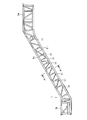
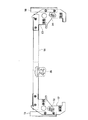
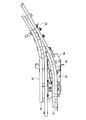
図1は、本発明のリニューアル方法の一実施の形態を適用したエスカレータのトラス1の全体を示す側面図である。図2は、図1のA−A断面図である。図1においては、トラス1内に取り付けられている部品を取り外した後に、トラス1の上階側の乗降部1a及び下階側の乗降部1bの間にある中間部1cに、複数のガイドレール支持ユニット11が取り付けられた、リニューアル後のトラスを示している。ガイドレール支持ユニット11は、後述するように、左右のガイドレールを支持する部材を一体化したものであって、トラス1を構成する縦梁部材2及び横梁部材3に対して締結手段により締結固定されている。
FIG. 1 is a side view showing an
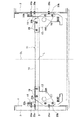
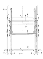
ガイドレール支持ユニット11は、図2の断面図に示されるように、往路側及び帰路側の複数のガイドレールを支持する左右一対のガイドレール支持体、すなわち、左側ガイドレール支持体12及び右側ガイドレール支持体13と、左側ガイドレール支持体12及び右側ガイドレール支持体13との間に掛け渡されて左側ガイドレール支持体12及び右側ガイドレール支持体13を連結固定する連結棒材14と、左側ガイドレール支持体12を縦梁部材2に取り付けられるための取付部材15及び右側ガイドレール支持体を縦梁部材2に取り付けるための取付部材16とを備えている。
As shown in the sectional view of FIG. 2, the guide
左側ガイドレール支持体12と前記連結棒材14とは、例えば溶接などより固定されている。同様に、右側ガイドレール支持体13と前記連結棒材14とは、例えば溶接などにより固定されている。また、左側ガイドレール支持体12と前記取付部材15とは、ボルト及びナットよりなる締結具17で締結固定されていて、右側ガイドレール支持体13と前記取付部材16とは、ボルト及びナットよりなる締結具18で締結固定されている。
The left
本実施の形態においてエスカレータのリニューアルは、次の要領で行う。 In this embodiment, the escalator is renewed in the following manner.
まず、既設のエスカレータのトラス1内に取り付けられている各種の部品を取り外す。そして、部品が取り外されたトラス1に対して、ガイドレール支持ユニット11と位置合わせをするための目印を設ける。位置合わせは通常、トラス1の幅方向中央の位置と、ガイドレール支持ユニット11の幅方向中央の位置と合わせることにより行われるので、トラスに設ける目印は、トラスの芯出し作業により形成される。
First, various parts attached in the
また、別途、ガイドレール支持ユニット11を組み立てて準備しておく。この組み立ては、左右のガイドレール支持体12及び13と連結棒材14と、溶接により接合するとともに、左右のガイドレール支持体12及び13と取り付け部材15、16とを締結具17、18により締結固定することにより行われ、一体的なガイドレール支持ユニット11を用意する。
Separately, the guide
ガイドレール支持ユニット11に、トラス1と位置合わせをする目印を形成しておくことが有利である。目印は、例えば、図2に示すように、連結棒材14の幅方向中央位置に、罫書き線Lを引いておけばよい。
It is advantageous to form marks on the guide
次に、組み立てたガイドレール支持ユニット11を、既設のトラス1に取り付ける。この取り付けの際に、芯出し作業によるトラス1の幅方向中心位置の目印と、ガイドレール支持ユニット11の連結棒材14に形成された罫書き線Lとを位置合わせするようにガイドレール支持ユニット11を配置する。
Next, the assembled guide
次いで、トラス1の横梁部材3に設けられている貫通孔とガイドレール支持ユニット11の連結棒材14に形成した貫通孔とに、取付ボルト19を通して、ナットにより締結することにより、ガイドレール支持ユニット11を既設トラスの1の横梁部材3に取り付け固定する。また、既設のトラス1の縦梁部材2に設けられている貫通孔と、ガイドレール支持ユニット11の取付部材15、16に形成した貫通孔とに、取付ボルト20aを通して、ナット20bにより締結することにより、ガイドレール支持ユニット11を既設トラスの1の縦梁部材2に取り付け固定する。
Next, the guide rail support unit is fastened with a nut through a
本実施形態のリニューアル方法によれば、左右のガイドレールを支持する部材を一体化したガイドレール支持ユニット11を用いていることから、かかるガイドレール支持ユニット11をトラス1に取り付ける際の位置合わせが、トラス1の中央位置とガイドレール支持ユニット11の中央位置とを合わせるだけで済むので、位置合わせ作業が簡略化され、リニューアル作業時間を従来に比べて大幅に短縮することができる。
According to the renewal method of the present embodiment, since the guide
また、既設のトラス1に既にあいている孔を利用して、既設のトラス1に新たに加工することなくガイドレール支持ユニット11を取り付けることにより、リニューアル作業時間のいっそうの短縮化を図ることができる。
Further, by using the holes already provided in the existing
さらに、本実施形態のリニューアル方法は、踏段幅及び踏段を案内するためのガイドレール幅が、リニューアル前後で異なる場合であっても、ガイドレール幅を容易に寸法出しすることが可能なガイドレール支持ユニット11を用いることにより、組み立て時間の削減及び作業内容の簡素化を図ることができるので好ましい。
Furthermore, the renewal method of this embodiment is a guide rail support that can easily measure the guide rail width even when the step width and the guide rail width for guiding the step are different before and after the renewal. Use of the
また更に、実施形態のリニューアル方法は、左側ガイドレール支持体12及び右側ガイドレール支持体13のいずれも、往路側ガイドレール及び復路側ガイドレールの両者が一体的に取り付けられるものであるから、従来技術のように、往路側新設ユニットと帰路側新設ユニットを連結する作業が不要であり、作業時間のいっそうの短縮化を図ることができる。
Furthermore, in the renewal method of the embodiment, since both the left
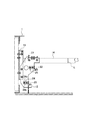
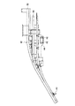
図3には、ガイドレール支持ユニット11の左側ガイドレール支持体12に、往路側ガイドレール21、帰路側の後輪用ガイドレール22、帰路側の前輪用ガイドレール23を取り付けたところを示している。左右の複数のレールを支えるための左側ガイドレール支持体12及び右側ガイドレール支持体13には、リニューアル後に使用する踏段の踏段ローラの幅に合わせた位置に、往路側ガイドレール21、帰路側の後輪用ガイドレール22、帰路側の前輪用ガイドレール23が取り付けられるように切欠部が形成されている。したがって、左側ガイドレール支持体12及び右側ガイドレール支持体13の切欠部に、往路側ガイドレール21、帰路側の後輪用ガイドレール22、帰路側の前輪用ガイドレール23をそれぞれ当接するように取り付け固定するだけで、各ガイドレールの幅を所定の寸法にすることができるので、リニューアル作業時にガイドレールの幅を調整する作業を省略することができる。
FIG. 3 shows the left side
また、図3に示した左側ガイドレール支持体12は、左右のガイドレール間の距離を調整する調整手段24、25を有している。図3に示した調整手段24、25は、ガイドレール23については、ガイドレール23に当接する調整プレート24aと、この調整プレート24aの厚み方向を貫いて取り付けられたボルト24bと、このボルト24bを貫通させるために左側ガイドレール支持体12に形成された水平方向に伸びる長円形の貫通孔(図示せず)と、左側レール支持体の背面で長円形の貫通孔を貫通させたボルト24bと螺合するナット(図示せず)からなり、調整プレート24aが水平方向に移動可能に固定されている。かかる調整プレート24aにより、ガイドレール23の位置を規制することにより、左右のガイドレール間の距離を微調整することができる。ガイドレール22の調整手段も同様である。
Also, the left
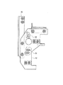
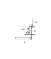
本発明の実施の形態で用いられるガイドレール支持ユニット11は、既に述べたようにトラス1の縦梁部材2及び横梁部材3に、ボルトとナットとにより締結固定されることにより、トラス1に取り付けられる。かかるガイドレール支持ユニット11の取り付け時に必要なボルト、ナットなどの締結部材を、リニューアル作業の前に、予め、取り付ける位置ごとに区分けし、かつ、そのガイドレール支持ユニット11の取り付け位置近傍に設けておくことにより、使用するボルトなどを他の場所から持ってくる作業が不要になり、リニューアル作業がいっそう容易になる。したがって、図4及び図5に示すように、取り付ける位置ごとに区分けされた締結部材を収めた袋31〜35を、ガイドレール支持ユニット11に粘着性テープなどにより取り付けることは、有利である。また、その袋31〜35の中に、注意書きや指示書を一緒に収容させておけば、リニューアル作業を能率よく行うことができる。なお、締結部材は、図4及び図5に示した袋31〜35に収容する他、締結しようとする部材に仮止めすることもできる。
The guide
ガイドレールは、ガイドレール支持ユニット11をトラス1内に取り付けた後に、ガイドレール支持ユニット11に対して取り付けてもよいが、リニューアル作業の前に、予めガイドレール支持ユニット11に取り付けておき、かかるガイドレールを取り付けたガイドレール支持ユニット11をトラス1に取り付けるようにしてもよい。特に、トラス1の上階側の乗降部1a及び下階側の乗降部1bにおいては、左右の複数の往路側ガイドレールを、左右のガイドレールを支持する部材を一体化したガイドレール支持ユニットに予め組み込むことにより、既設トラスが設けられた現地でのガイドレール取り付け作業を無くすことができるので有利である。
The guide rail may be attached to the guide
図6〜8は、トラス1の上階側の乗降部1aに取り付けられるガイドレール支持ユニット41に複数の複数の往路側ガイドレール51〜54が取り付けられているところを示す図であり、図6は平面図、図7はその右側面図、図8は右側端部近傍の部分断面図である。図6〜8において、ガイドレール支持ユニット41は、トラスの幅方向にわたって設けられた連結棒材42及び連結アングル43と、トラスの幅方向両端部近傍に設けられ、連結棒材42及び連結アングル43と連結固定される左右一対のガイドレール支持体44とを有している。エスカレータのリニューアル作業に際して、左側のガイドレール支持体44に、往路側の左側ガイドレール51及び53が取り付けられ、右側のガイドレール支持体44に、往路側の右側ガイドレール52及び54が取り付けられる。また、連結棒材42及び連結アングル43の少なくとも一つには、幅方向中央位置を示す罫書き線Lが引かれる。
6-8 is a figure which shows the place where the several some outward guide rails 51-54 are attached to the guide
そして、リニューアル作業時には、このように複数の往路側ガイドレール51〜54が取り付けられたガイドレール支持ユニット41を、トラス1の芯出し作業により幅方向中央位置に形成された目印と、連結棒材42及び連結アングル43の少なくとも一つに形成された罫書き線Lとを位置合わせして、トラス1に取り付ける。かくして、既設トラスが設けられた現地でのガイドレール取り付け作業を無くすことができるので、リニューアル作業をいっそう能率よく行うことができる。
When the renewal work is performed, the guide
図9及び図10は、トラス1の下階側の乗降部1bに取り付ける、ガイドレール支持ユニット61に複数の複数の往路側ガイドレール71〜74が取り付けられているところを示す図であり、図9は平面図、図10はその右側面図、図8は右側端部近傍の部分断面図である。図9及び図10において、ガイドレール支持ユニット61は、トラスの幅方向にわたって設けられた連結棒材62及び連結アングル63と、トラスの幅方向両端部近傍に設けられ、連結棒材62及び連結アングル63と連結固定される左右一対のガイドレール支持体64とを有している。エスカレータのリニューアル作業に際して、左側のガイドレール支持体44に、往路側の左側ガイドレール71及び73が取り付けられ、右側のガイドレール支持体44に、往路側の右側ガイドレール72及び74が取り付けられる。また、連結棒材62及び連結アングル63の少なくとも一つには、幅方向中央位置を示す罫書き線Lが引かれる。
9 and 10 are views showing a plurality of forward-
そして、リニューアル作業時には、このように複数の往路側ガイドレール71〜74が取り付けられたガイドレール支持ユニット61を、トラス1の芯出し作業により幅方向中央位置に形成された目印と、連結棒材62及び63の少なくとも一つに形成された罫書き線Lとを位置合わせして、トラス1に取り付ける。かくして、既設トラスが設けられた現地でのガイドレール取り付け作業を無くすことができるので、リニューアル作業をいっそう能率よく行うことができる。
When the renewal work is performed, the guide
既設のトラス1から、縦梁部材2及び横梁部材3を残して既設部品を予め撤去し、既設のトラス1の芯出し作業を行った。また、ガイドレール支持ユニット11を予め専用治具などで寸法出しを行っておき、左右のガイドレール支持体12及び13と、連結棒材14とを溶接して一体化しておいた。そして、連結棒材14の幅方向中央位置に、罫書き線Lを引いた。
From the existing
エスカレータのリニューアル作業の際は、既設のトラス1の幅方向中央位置に設けられた目印と、ガイドレール支持ユニット11の連結棒材14に引かれた罫書き線Lとを位置合わせするだけ済み、従来の改修方法のように左右のガイドレール支持体12、13をトラスの中心から寸法合わせをする必要がなく、容易に既設のトラス1に組み込むことができた。
When renewing the escalator, it is only necessary to align the mark provided at the center in the width direction of the existing
また、ガイドレール21、22及び23の取り付けについては、あらかじめガイドレール支持ユニット11に形成されている切欠部が、取り付けようとするガイドレール21、22及び23の幅方向間隔を考慮した位置に形成されているので、これらのガイドレール21、22及び23をガイドレール支持ユニット11の切欠部にそのまま取り付けるだけで、所定のガイドレール幅にすることができた。
As for the attachment of the guide rails 21, 22 and 23, the notch formed in advance in the guide
上階側の乗降部1aに取り付けられるガイドレール支持ユニット41及び下階側の乗降部1bに取り付けられるガイドレール支持ユニット61についても、あらかじめ寸法出しを行っているので、既設のトラス1に取り付けは、既設のトラス1の幅方向中央位置に設けられた目印と、ガイドレール支持ユニット41、61の幅方向中央位置の罫書き線を合わせるだけで、所定の寸法位置合わせができた。
The guide
このため,ガイドレールを支持する各部材を現地で組み立てたり、部品を集荷したりする時間が不要となって、従来よりも著しく組み立て時間が短縮され、リニューアル作業時間の短縮化が図られた。 This eliminates the time for assembling each member that supports the guide rail and collecting parts on site, so that the assembly time is significantly reduced compared to the conventional method, and the renewal work time is shortened.
また、左右のガイドレールを支持する部材を一体化したガイドレール支持ユニット11、41、61を用いたことから、リニューアルをする既設トラスの現地にて、数ある部材がどの部材かを判断したり、加工したりする時間が不要となるので、作業現地において部品を置くためのスペースペースが著しく少なくて済んだ。
In addition, since the guide
上記により、既設のトラス1の強度を確保しつつリニューアルによりエスカレータの安全性が増し、かつ、リニューアル作業を容易にすることができ工期の短縮が図られた。
As described above, the safety of the escalator is increased by renewal while ensuring the strength of the existing
1 トラス
11 ガイドレール支持ユニット
12 左側ガイドレール支持体(左ガイドレール支持ユニット)
13 右側ガイドレール支持体(右ガイドレール支持ユニット)
14 連結棒材(連結部材)
21、22,23 ガイドレール
24、25 調整手段
31、32、33、34、35 袋
CL 中心線
L 罫書き線
1
13 Right guide rail support (right guide rail support unit)
14 Connecting rod (connecting member)
21, 22, 23
Claims (8)
部品が取り外されたトラスに対して、位置合わせ用の目印を設ける工程と、
左右のガイドレールを支持する部材を一体化したガイドレール支持ユニットを用意する工程と、
ガイドレール支持ユニットを、部品が取り外されたトラスに設けられた目印に合わせて位置決めをし、トラスに取り付ける工程と、
を有することを特徴とする乗客コンベアのリニューアル方法。 Removing the parts installed in the truss of the existing passenger conveyor;
Providing a mark for alignment on the truss from which the part has been removed;
Preparing a guide rail support unit in which members for supporting the left and right guide rails are integrated;
Positioning the guide rail support unit in accordance with a mark provided on the truss from which the component has been removed, and attaching the guide rail support unit to the truss;
A method for renewing a passenger conveyor, comprising:
Priority Applications (1)
| Application Number | Priority Date | Filing Date | Title |
|---|---|---|---|
| JP2004112332A JP4703974B2 (en) | 2004-04-06 | 2004-04-06 | Passenger conveyor renewal method and guide rail support unit |
Applications Claiming Priority (1)
| Application Number | Priority Date | Filing Date | Title |
|---|---|---|---|
| JP2004112332A JP4703974B2 (en) | 2004-04-06 | 2004-04-06 | Passenger conveyor renewal method and guide rail support unit |
Publications (2)
| Publication Number | Publication Date |
|---|---|
| JP2005298075A true JP2005298075A (en) | 2005-10-27 |
| JP4703974B2 JP4703974B2 (en) | 2011-06-15 |
Family
ID=35330094
Family Applications (1)
| Application Number | Title | Priority Date | Filing Date |
|---|---|---|---|
| JP2004112332A Expired - Lifetime JP4703974B2 (en) | 2004-04-06 | 2004-04-06 | Passenger conveyor renewal method and guide rail support unit |
Country Status (1)
| Country | Link |
|---|---|
| JP (1) | JP4703974B2 (en) |
Cited By (6)
| Publication number | Priority date | Publication date | Assignee | Title |
|---|---|---|---|---|
| JP2009263062A (en) * | 2008-04-24 | 2009-11-12 | Hitachi Ltd | Passenger conveyor |
| CN101941635A (en) * | 2009-07-07 | 2011-01-12 | 株式会社日立制作所 | Apparatus of passenger conveyor |
| CN103663078A (en) * | 2013-11-29 | 2014-03-26 | 西尼电梯(杭州)有限公司 | Guide rail type upper and lower ladder way assembly for escalator |
| CN112406387A (en) * | 2019-08-21 | 2021-02-26 | 三菱电机大楼技术服务株式会社 | Processing device |
| CN113860128A (en) * | 2020-06-30 | 2021-12-31 | 蒂森克虏伯电梯创新与运营有限公司 | Connecting support piece for truss of escalator or moving pavement |
| WO2025213364A1 (en) * | 2024-04-09 | 2025-10-16 | 通力电梯有限公司 | Adjustable rail system for escalator |
Families Citing this family (1)
| Publication number | Priority date | Publication date | Assignee | Title |
|---|---|---|---|---|
| FI4353650T3 (en) * | 2022-10-10 | 2025-12-12 | Tk Elevator Innovation & Operations Gmbh | Support structure for a guideway device |
Citations (6)
| Publication number | Priority date | Publication date | Assignee | Title |
|---|---|---|---|---|
| JPS50112989A (en) * | 1974-02-16 | 1975-09-04 | ||
| JPS58191174U (en) * | 1982-06-14 | 1983-12-19 | 三菱電機株式会社 | Renewal structure of existing escalator |
| JPH0480192A (en) * | 1990-07-23 | 1992-03-13 | Toshiba Corp | Supporting device for guide rail of man conveyor |
| JPH07189343A (en) * | 1993-12-27 | 1995-07-28 | Sekisui Chem Co Ltd | Building unit |
| JP2002193576A (en) * | 2000-12-25 | 2002-07-10 | Mitsubishi Electric Corp | Passenger conveyor and its repair method |
| JP2002332183A (en) * | 2001-05-08 | 2002-11-22 | Hitachi Building Systems Co Ltd | Passenger conveyor railing renewal method |
-
2004
- 2004-04-06 JP JP2004112332A patent/JP4703974B2/en not_active Expired - Lifetime
Patent Citations (6)
| Publication number | Priority date | Publication date | Assignee | Title |
|---|---|---|---|---|
| JPS50112989A (en) * | 1974-02-16 | 1975-09-04 | ||
| JPS58191174U (en) * | 1982-06-14 | 1983-12-19 | 三菱電機株式会社 | Renewal structure of existing escalator |
| JPH0480192A (en) * | 1990-07-23 | 1992-03-13 | Toshiba Corp | Supporting device for guide rail of man conveyor |
| JPH07189343A (en) * | 1993-12-27 | 1995-07-28 | Sekisui Chem Co Ltd | Building unit |
| JP2002193576A (en) * | 2000-12-25 | 2002-07-10 | Mitsubishi Electric Corp | Passenger conveyor and its repair method |
| JP2002332183A (en) * | 2001-05-08 | 2002-11-22 | Hitachi Building Systems Co Ltd | Passenger conveyor railing renewal method |
Cited By (10)
| Publication number | Priority date | Publication date | Assignee | Title |
|---|---|---|---|---|
| JP2009263062A (en) * | 2008-04-24 | 2009-11-12 | Hitachi Ltd | Passenger conveyor |
| CN101941635A (en) * | 2009-07-07 | 2011-01-12 | 株式会社日立制作所 | Apparatus of passenger conveyor |
| JP2011016605A (en) * | 2009-07-07 | 2011-01-27 | Hitachi Ltd | Passenger conveyor |
| CN103663078A (en) * | 2013-11-29 | 2014-03-26 | 西尼电梯(杭州)有限公司 | Guide rail type upper and lower ladder way assembly for escalator |
| CN112406387A (en) * | 2019-08-21 | 2021-02-26 | 三菱电机大楼技术服务株式会社 | Processing device |
| JP2021031218A (en) * | 2019-08-21 | 2021-03-01 | 三菱電機ビルテクノサービス株式会社 | Processing equipment |
| CN112406387B (en) * | 2019-08-21 | 2023-08-11 | 三菱电机楼宇解决方案株式会社 | Processing device |
| CN113860128A (en) * | 2020-06-30 | 2021-12-31 | 蒂森克虏伯电梯创新与运营有限公司 | Connecting support piece for truss of escalator or moving pavement |
| CN113860128B (en) * | 2020-06-30 | 2024-01-05 | 蒂森克虏伯电梯创新与运营有限公司 | Connecting support for an escalator or a travelator truss |
| WO2025213364A1 (en) * | 2024-04-09 | 2025-10-16 | 通力电梯有限公司 | Adjustable rail system for escalator |
Also Published As
| Publication number | Publication date |
|---|---|
| JP4703974B2 (en) | 2011-06-15 |
Similar Documents
| Publication | Publication Date | Title |
|---|---|---|
| EP1558515B1 (en) | Method of escalator modernization | |
| JP6896775B2 (en) | How to modernize an escalator or moving walkway | |
| JP6513585B2 (en) | Shape holding jig and aircraft panel manufacturing method | |
| CN101565149B (en) | Passenger Conveyor | |
| US20130192952A1 (en) | Profile track integrated drive system | |
| KR20150063472A (en) | Track system for an escalator or moving pavement | |
| JP4703974B2 (en) | Passenger conveyor renewal method and guide rail support unit | |
| JP2009184771A (en) | Passenger conveyer and renewal method of the same | |
| KR102479683B1 (en) | A system for combining axis and wheel of train by press type | |
| EP3502032A1 (en) | A roller guide assembly, an elevator system, an installation method for installing a roller guide assembly and a maintenance method for maintaining a roller guide assembly | |
| CN209736897U (en) | equipment cabin camber beam assembly welding frock | |
| CN214489383U (en) | Box roof beam assembly positioning is with pressing from both sides roof beam frame | |
| JP4809976B2 (en) | Passenger conveyor | |
| CN101830389B (en) | Passenger Conveyor | |
| KR102479682B1 (en) | A system for combining axis and wheel of train by press type | |
| JP4387829B2 (en) | Replacement escalator, replacement escalator assembly jig, and escalator renewal method | |
| JP2012153526A (en) | Rail support structure of passenger conveyor | |
| JPH08143259A (en) | Man conveyor rail | |
| JPH07276092A (en) | Cutting surface plate | |
| CN220952968U (en) | Multi-station construction device for bridge assembly | |
| CN116136078B (en) | A bridge beam bottom inspection device | |
| JP2004278210A (en) | Joining method of small beam and large beam and joining structure of small beam and large beam | |
| JPH03200691A (en) | Connecting structure of guide rail for man conveyor | |
| JP2025024340A (en) | Simple work booth | |
| JPH05193885A (en) | Guide rail support device for escalator |
Legal Events
| Date | Code | Title | Description |
|---|---|---|---|
| A621 | Written request for application examination |
Free format text: JAPANESE INTERMEDIATE CODE: A621 Effective date: 20070320 |
|
| A977 | Report on retrieval |
Free format text: JAPANESE INTERMEDIATE CODE: A971007 Effective date: 20090911 |
|
| A131 | Notification of reasons for refusal |
Free format text: JAPANESE INTERMEDIATE CODE: A131 Effective date: 20090915 |
|
| A521 | Request for written amendment filed |
Free format text: JAPANESE INTERMEDIATE CODE: A523 Effective date: 20091116 |
|
| A131 | Notification of reasons for refusal |
Free format text: JAPANESE INTERMEDIATE CODE: A131 Effective date: 20100706 |
|
| A521 | Request for written amendment filed |
Free format text: JAPANESE INTERMEDIATE CODE: A523 Effective date: 20100903 |
|
| TRDD | Decision of grant or rejection written | ||
| A01 | Written decision to grant a patent or to grant a registration (utility model) |
Free format text: JAPANESE INTERMEDIATE CODE: A01 Effective date: 20110215 |
|
| A61 | First payment of annual fees (during grant procedure) |
Free format text: JAPANESE INTERMEDIATE CODE: A61 Effective date: 20110309 |
|
| R150 | Certificate of patent or registration of utility model |
Ref document number: 4703974 Country of ref document: JP Free format text: JAPANESE INTERMEDIATE CODE: R150 |
|
| S531 | Written request for registration of change of domicile |
Free format text: JAPANESE INTERMEDIATE CODE: R313531 |
|
| R350 | Written notification of registration of transfer |
Free format text: JAPANESE INTERMEDIATE CODE: R350 |
|
| EXPY | Cancellation because of completion of term |