JP2005297948A - POWER TRANSMISSION DEVICE, POWER OUTPUT DEVICE, AUTOMOBILE MOUNTING THE SAME, CONTROL METHOD FOR POWER OUTPUT DEVICE - Google Patents
POWER TRANSMISSION DEVICE, POWER OUTPUT DEVICE, AUTOMOBILE MOUNTING THE SAME, CONTROL METHOD FOR POWER OUTPUT DEVICE Download PDFInfo
- Publication number
- JP2005297948A JP2005297948A JP2005009196A JP2005009196A JP2005297948A JP 2005297948 A JP2005297948 A JP 2005297948A JP 2005009196 A JP2005009196 A JP 2005009196A JP 2005009196 A JP2005009196 A JP 2005009196A JP 2005297948 A JP2005297948 A JP 2005297948A
- Authority
- JP
- Japan
- Prior art keywords
- power
- motor
- output
- internal combustion
- combustion engine
- Prior art date
- Legal status (The legal status is an assumption and is not a legal conclusion. Google has not performed a legal analysis and makes no representation as to the accuracy of the status listed.)
- Granted
Links
Images


Classifications
-
- Y—GENERAL TAGGING OF NEW TECHNOLOGICAL DEVELOPMENTS; GENERAL TAGGING OF CROSS-SECTIONAL TECHNOLOGIES SPANNING OVER SEVERAL SECTIONS OF THE IPC; TECHNICAL SUBJECTS COVERED BY FORMER USPC CROSS-REFERENCE ART COLLECTIONS [XRACs] AND DIGESTS
- Y02—TECHNOLOGIES OR APPLICATIONS FOR MITIGATION OR ADAPTATION AGAINST CLIMATE CHANGE
- Y02T—CLIMATE CHANGE MITIGATION TECHNOLOGIES RELATED TO TRANSPORTATION
- Y02T10/00—Road transport of goods or passengers
- Y02T10/60—Other road transportation technologies with climate change mitigation effect
- Y02T10/62—Hybrid vehicles
Landscapes
- Control Of Driving Devices And Active Controlling Of Vehicle (AREA)
- Control Of Vehicle Engines Or Engines For Specific Uses (AREA)
- Control Of Transmission Device (AREA)
- Electric Propulsion And Braking For Vehicles (AREA)
- Hybrid Electric Vehicles (AREA)
Abstract
【課題】 変速機の変速段を切り替える際における駆動軸へのトルクの落ち込みや変速ショックを抑制する。
【解決手段】 変速機60における変速段の切替が要求されたときには、バッテリ50の入力制限Winの範囲内でエンジントルク反力を受け持つモータMG1の発電を伴って駆動軸に要求される要求トルクTr*のすべてをエンジン22から動力分配統合機構30を介してリングギヤ軸32aに伝達されるトルクで賄うようにエンジン22とモータMG1,MG2とを制御し、その後に変速段の切替を行なう。これにより、モータMG2から駆動軸に出力すべきトルクを略値0にしてから変速段を切り替えることができるから、変速段の切替の際のトルクの落ち込みや変速ショックを抑制することができる。
【選択図】 図1PROBLEM TO BE SOLVED: To suppress a drop in torque on a drive shaft and a shift shock when switching a shift stage of a transmission.
SOLUTION: When switching of a gear position in a transmission 60 is requested, a required torque Tr required for a drive shaft accompanied by power generation of a motor MG1 responsible for an engine torque reaction force within a range of an input limit Win of a battery 50. The engine 22 and the motors MG1 and MG2 are controlled so that all of * is covered by the torque transmitted from the engine 22 to the ring gear shaft 32a via the power distribution and integration mechanism 30, and then the gear stage is switched. As a result, the gear stage can be switched after the torque to be output from the motor MG2 to the drive shaft is substantially zero, so that a drop in torque and a gear shift shock during switching of the gear stage can be suppressed.
[Selection] Figure 1
Description
本発明は、動力伝達装置および動力出力装置並びにこれを搭載する自動車、動力出力装置の制御方法に関し、詳しくは、内燃機関からの動力を駆動軸に伝達可能な動力伝達装置および内燃機関と動力伝達装置とを備える動力出力装置並びに動力出力装置を搭載し駆動軸が車軸に連結されて走行する自動車、動力出力装置の制御方法に関する。 The present invention relates to a power transmission device, a power output device, a vehicle equipped with the power transmission device, and a control method for the power output device, and more particularly, a power transmission device capable of transmitting power from an internal combustion engine to a drive shaft, and the internal combustion engine and power transmission. TECHNICAL FIELD The present invention relates to a power output device including a device, a vehicle mounted with a power output device, and a drive shaft connected to an axle, and a method for controlling the power output device.
従来、この種の動力伝達装置としては、遊星歯車機構の各回転要素にエンジンの出力軸と発電機の回転軸と駆動軸とを接続すると共に駆動軸に変速機を介して電動機の回転軸を接続した自動車に搭載されたものが提案されている(特許文献1参照)。この装置では、変速機の変速段を車速に応じて変更することにより電動機からの動力を車速に応じた動力に変換して駆動軸に出力している。
上述の動力伝達装置では、変速段を変更する際に駆動軸に出力される駆動力に落ち込みが生じたり変速ショックが生じたりする場合がある。電動機から駆動軸に変速機を介して駆動力が出力されている状態で変速段を変更したとき、駆動軸に伝達される駆動力の一部が変速段の変更に必要なクラッチやブレーキにより消費されるから、駆動軸に出力される駆動力に変動が生じ、乗員に違和感を生じさせてしまう。 In the above-described power transmission device, when changing the gear position, the driving force output to the drive shaft may be depressed or a shift shock may occur. When the gear stage is changed while the driving force is being output from the motor to the drive shaft via the transmission, a part of the driving force transmitted to the drive shaft is consumed by the clutch or brake necessary for the change of the gear stage. As a result, the driving force output to the driving shaft fluctuates, causing the passenger to feel uncomfortable.
本発明の動力伝達装置および動力出力装置並びにこれを搭載する自動車、動力出力装置の制御方法は、駆動軸と電動機との間の動力の伝達を行なう変速機の変速比を変更する際の駆動力の落ち込みや変速ショックを抑制することを目的の一つとする。また、本発明の動力伝達装置および動力出力装置並びにこれを搭載する自動車、動力出力装置の制御方法は、駆動軸と電動機との間の動力の伝達を行なう変速機の変速比を変更する際の蓄電装置への過大な電力による充電や過充電を防止することを目的の一つとする。さらに、本発明の動力伝達装置および動力出力装置並びにこれを搭載する自動車、動力出力装置の制御方法は、電動機から出力されるパワーを保持しながら変速機の変速比を変更する等パワー変速を行なう際の駆動力の落ち込みや変速ショックを抑制することを目的の一つとする。 The power transmission device, the power output device, the automobile equipped with the power transmission device, and the control method for the power output device according to the present invention include a driving force for changing a transmission gear ratio for transmitting power between a drive shaft and an electric motor. One of the purposes is to suppress the drop of gear and shift shock. In addition, the power transmission device, the power output device, the automobile equipped with the power transmission device, and the control method for the power output device according to the present invention provide a method for changing the gear ratio of the transmission that transmits power between the drive shaft and the electric motor. One of the purposes is to prevent charging or overcharging of the power storage device due to excessive electric power. Furthermore, the power transmission device, the power output device, the vehicle equipped with the power transmission device, and the control method for the power output device according to the present invention perform an equal power shift by changing the gear ratio of the transmission while maintaining the power output from the motor. One of the purposes is to suppress a drop in driving force and shift shock at the time.
本発明の動力伝達装置および動力出力装置並びにこれを搭載する自動車、動力出力装置の制御方法は、上述の目的の少なくとも一部を達成するために以下の手段を採った。 The power transmission device, the power output device, the automobile equipped with the power transmission device, and the control method for the power output device of the present invention employ the following means in order to achieve at least a part of the above object.
本発明の動力伝達装置は、
内燃機関からの動力を駆動軸に伝達可能な動力伝達装置であって、
前記内燃機関の出力軸と前記駆動軸とに接続され、該内燃機関からの動力の少なくとも一部を電力に変換すると共に残余の動力を該駆動軸に伝達可能な電力変換動力伝達手段と、
動力を入出力可能な電動機と、
変更可能な変速比をもって前記電動機と前記駆動軸との間の動力の伝達を行なう変速伝達手段と、
前記電力変換動力伝達手段および前記電動機と電力のやり取りが可能な蓄電手段と、
前記駆動軸に要求される要求駆動力に基づいて前記内燃機関から出力すべき目標動力を設定する目標動力設定手段と、
該設定された目標動力と前記内燃機関に適用した条件とに基づいて該内燃機関の動作点を設定し、該設定した動作点で該内燃機関が運転されると共に前記要求駆動力に対応する
駆動力が前記駆動軸に出力されるよう前記内燃機関と前記電力変換動力伝達手段と前記電動機とを駆動制御する駆動制御手段と、
前記変速伝達手段における変速比の切替が指示されたとき、前記駆動制御手段に代えて、前記設定された目標動力に基づいて前記蓄電手段の入力制限の範囲内で該駆動制御手段により設定される動作点とは異なる動作点を設定し、該設定した動作点で前記内燃機関が運転されると共に前記要求駆動力に対応する駆動力が前記駆動軸に出力されるよう前記内燃機関と前記電力変換動力伝達手段と前記電動機とを駆動制御し、前記設定した動作点で前記内燃機関を運転させた後に前記変速伝達手段における変速比が切り替えられるよう該変速伝達手段を駆動制御する変速切替時駆動制御手段と
を備えることを要旨とする。
The power transmission device of the present invention is
A power transmission device capable of transmitting power from an internal combustion engine to a drive shaft,
Power conversion power transmission means connected to the output shaft and the drive shaft of the internal combustion engine, capable of converting at least part of the power from the internal combustion engine into electric power and transmitting the remaining power to the drive shaft;
An electric motor that can input and output power;
Shift transmission means for transmitting power between the electric motor and the drive shaft with a changeable gear ratio;
Power storage means capable of exchanging power with the power conversion power transmission means and the electric motor;
Target power setting means for setting target power to be output from the internal combustion engine based on a required driving force required for the drive shaft;
An operating point of the internal combustion engine is set based on the set target power and a condition applied to the internal combustion engine, and the internal combustion engine is operated at the set operating point and a drive corresponding to the required driving force Drive control means for drivingly controlling the internal combustion engine, the power conversion power transmission means, and the electric motor so that force is output to the drive shaft;
When switching of the transmission gear ratio in the transmission transmission unit is instructed, instead of the drive control unit, it is set by the drive control unit within the range of the input limit of the power storage unit based on the set target power. An operating point different from the operating point is set, and the internal combustion engine and the power conversion are operated so that the internal combustion engine is operated at the set operating point and a driving force corresponding to the required driving force is output to the driving shaft. Drive control at the time of shift switching that controls driving of the power transmission means and the electric motor, and drives the transmission transmission means so that the gear ratio in the transmission transmission means is switched after the internal combustion engine is operated at the set operating point. And a means.
この本発明の動力伝達装置では、駆動軸に要求される要求駆動力に基づいて設定される内燃機関から出力すべき目標動力と内燃機関に適用した条件とに基づいて動作点を設定しこの設定した動作点で内燃機関が運転されると共に要求駆動力に対応する駆動力が駆動軸に出力されるよう内燃機関と電力変換動力伝達手段と電動機とを駆動制御し、電動機と駆動軸との間の動力の伝達を行なう変速伝達手段における変速比の切替が指示されたとき、目標動力に基づいて蓄電手段の入力制限の範囲内で上述の駆動制御により設定される動作点とは異なる動作点を設定しこの設定した動作点で内燃機関が運転されると共に要求駆動力に対応する駆動力が駆動軸に出力されるよう内燃機関と電力変換動力伝達手段と電動機とを駆動制御し、設定した動作点で内燃機関を運転させた後に変速伝達手段における変速比が切り替えられるよう変速伝達手段を駆動制御する。異なる動作点として、蓄電手段の入力制限の範囲内で要求駆動力における内燃機関から駆動軸に伝達される駆動力の割合ができる限り大きくなる動作点を設定するものとすれば、電動機から駆動軸に出力する駆動力の割合を小さくすることができる。この結果、変速比を変更する際の駆動軸への駆動力の落ち込みや変速ショックを抑制することができる。もとより、蓄電手段の入力制限の範囲内で行なうから、蓄電手段への過大な電力による充電や過充電を防止することができる。 In this power transmission device of the present invention, the operating point is set based on the target power to be output from the internal combustion engine set based on the required driving force required for the drive shaft and the conditions applied to the internal combustion engine. The internal combustion engine, the power conversion power transmission means, and the electric motor are driven and controlled so that the internal combustion engine is operated at the operating point and the driving force corresponding to the required driving force is output to the driving shaft. When switching of the transmission gear ratio is instructed in the transmission transmission means for transmitting the motive power, an operating point different from the operating point set by the drive control described above within the range of the input limit of the power storage means based on the target power is selected. The set operation is performed by controlling the internal combustion engine, the power conversion power transmission means, and the electric motor so that the internal combustion engine is operated at the set operating point and the driving force corresponding to the required driving force is output to the drive shaft. In controlling the driving of the speed change-transmission so that the speed ratio is switched in the transmission mechanism after by operating an internal combustion engine. As a different operating point, if the operating point at which the ratio of the driving force transmitted from the internal combustion engine to the driving shaft in the required driving force is within the range of the input restriction of the power storage means is set as large as possible, It is possible to reduce the ratio of the driving force output to. As a result, it is possible to suppress a drop in driving force to the drive shaft and a shift shock when changing the gear ratio. Of course, since it is performed within the range of the input restriction of the power storage means, it is possible to prevent the power storage means from being charged or overcharged by excessive electric power.
こうした本発明の動力伝達装置において、前記変速切替時駆動制御手段は、前記駆動制御手段により設定される内燃機関の動作点におけるトルクよりも高トルクの動作点を設定する手段であるものとすることもできる。 In such a power transmission device of the present invention, the shift control drive control means is a means for setting an operating point of torque higher than the torque at the operating point of the internal combustion engine set by the drive control means. You can also.
また、本発明の動力伝達装置において、前記変速切替時駆動制御手段は、前記電力変換動力伝達手段を介して前記内燃機関から前記駆動軸に伝達される駆動力が前記要求駆動力に対応する駆動力となるよう前記内燃機関と前記電力変換動力伝達手段とを駆動制御し、該駆動制御の後に前記変速伝達手段における変速比が切り替えられるよう該変速伝達手段を駆動制御する手段であるものとすることもできる。こうすれば、電動機から出力される駆動力を略値0としてから変速伝達手段における変速比の変更を行なうことができるから、変速比を変更する際の駆動軸への駆動力の落ち込みや変速ショックをより低減させることができる。 In the power transmission device according to the present invention, the drive control unit at the time of shift switching may be a drive in which a driving force transmitted from the internal combustion engine to the driving shaft via the power conversion power transmission unit corresponds to the required driving force. Drive control of the internal combustion engine and the power conversion power transmission means so as to be a force, and drive control of the transmission transmission means so that a gear ratio in the transmission transmission means is switched after the drive control. You can also. In this way, the transmission ratio in the transmission transmission means can be changed after the driving force output from the electric motor is set to a value of approximately 0. Therefore, when the transmission ratio is changed, a drop in the driving force on the drive shaft or a transmission shock is changed. Can be further reduced.
さらに、本発明の動力伝達装置において、前記変速切替時駆動制御手段は、前記電動機の状態と該電動機の出力制限とに基づいて該電動機から出力される電動機出力パワーを保持しながら前記変速伝達手段における変速比を切り替える等パワー変速を行なうことができるときには該電動機出力パワーによる等パワー変速が行なわれるよう該電動機と該変速伝達手段とを駆動制御し、前記電動機の状態と該電動機の出力制限とに基づいて等パワー変速を行なうことができないときには前記電動機出力パワーを等パワー変速が可能なパワーに調整すると共に該調整した電動機出力パワーによる等パワー変速が行なわれるよう該電動機と前記変速伝達手段とを駆動制御する手段であるものとすることもできる。こうすれば、等パワー変速を行なう際の駆動軸への駆動力の落ち込みや変速ショックをより低減させることができる。この場合、前記変速切替時駆動制御手段は、前記電動機の状態と該電動機の出力制限とに基づいて等パワー変速を行なうことができないときには、前記変速伝達手段における変速比を切り替えた際に前記電動機から出力可能な最大パワーを前記電動機出力パワーとして調整する手段であるものとすることもできる。こうすれば、電動機出力パワーをより容易に調整することができる。この場合、前記変速切替時駆動制御手段は、前記電動機の状態と該電動機の出力制限とに基づいて等パワー変速を行なうことができないときには、回転数の変更を伴わずに前記調整した電動機出力パワーが出力されるよう前記電動機を制御した後に該調整した電動機出力パワーによる等パワー変速が行なわれるよう前記電動機と前記変速伝達手段とを駆動制御する手段であるものとすることもできる。 Furthermore, in the power transmission device of the present invention, the shift switching drive control means maintains the motor output power output from the electric motor based on the state of the electric motor and the output limit of the electric motor. When the power ratio can be changed at a constant power ratio, the motor and the gear transmission means are driven and controlled so that the constant power shift by the motor output power is performed, and the state of the motor and the output limit of the motor are controlled. When the constant power shift cannot be performed based on the motor, the motor output power is adjusted to a power capable of equal power shift, and the motor and the shift transmission means are configured so that the equal power shift is performed by the adjusted motor output power. It may be a means for controlling the driving of the motor. By so doing, it is possible to further reduce a drop in driving force to the drive shaft and a shift shock when performing an equal power shift. In this case, the drive control means at the time of the shift switching can not perform the equal power shift based on the state of the motor and the output limit of the motor, and the motor when the gear ratio in the shift transmission means is switched. It is also possible to adjust the maximum power that can be output from the motor as the motor output power. In this way, the motor output power can be adjusted more easily. In this case, the drive control means at the time of the shift switching can adjust the output power of the motor without changing the number of revolutions when the same power shift cannot be performed based on the state of the motor and the output limit of the motor. It is also possible to control the drive of the electric motor and the shift transmission means so that an equal power shift by the adjusted electric motor output power is performed after the electric motor is controlled so as to be output.
本発明の動力伝達装置において、前記内燃機関に適用した条件は、該内燃機関が効率よく運転できる条件であるものとすることもできる。 In the power transmission device of the present invention, the conditions applied to the internal combustion engine may be conditions that allow the internal combustion engine to operate efficiently.
本発明の動力伝達装置において、前記電力変換動力伝達手段は、前記内燃機関の出力軸と前記駆動軸と第3の回転軸との3軸に接続され該3軸のうちのいずれか2軸に入出力される動力が決定されると残余の1軸に入出力される動力が決定される3軸式動力入出力手段と、前記第3の回転軸に動力を入出力可能な発電機とを備える手段であるものとすることもできるし、前記電力変換動力伝達手段は、前記内燃機関の出力軸に接続された第1の回転子と前記駆動軸に接続された第2の回転子とを有し、電磁的な作用により該内燃機関
からの動力の少なくとも一部を電力に変換すると共に残余の動力を該駆動軸に伝達する発電可能な対回転子電動機であるものとすることもできる。
In the power transmission device of the present invention, the power conversion power transmission means is connected to three axes of the output shaft of the internal combustion engine, the drive shaft, and a third rotating shaft, and any two of the three shafts are connected. A three-axis power input / output means for determining the power input / output to / from the remaining one shaft when the input / output power is determined; and a generator capable of inputting / outputting power to / from the third rotating shaft. The power conversion power transmission means may include a first rotor connected to the output shaft of the internal combustion engine and a second rotor connected to the drive shaft. It is also possible to provide a counter-rotor motor capable of generating electricity that converts at least part of the power from the internal combustion engine into electric power by electromagnetic action and transmits the remaining power to the drive shaft.
本発明では、動力伝達装置の態様の他、内燃機関と、上述した各態様のいずれかの本発明の動力伝達装置とを備える動力出力装置の態様とすることもできる。 In the present invention, in addition to the mode of the power transmission device, a mode of a power output device including the internal combustion engine and the power transmission device of any one of the above-described modes of the present invention can be used.
本発明の自動車は、
本発明の動力出力装置、即ち、内燃機関と、上述した各態様のいずれかの本発明の動力伝達装置、即ち、基本的には、内燃機関からの動力を駆動軸に伝達可能な動力伝達装置であって、前記内燃機関の出力軸と前記駆動軸とに接続され該内燃機関からの動力の少なくとも一部を電力に変換すると共に残余の動力を該駆動軸に伝達可能な電力変換動力伝達手段と、動力を入出力可能な電動機と、変更可能な変速比をもって前記電動機と前記駆動軸との間の動力の伝達を行なう変速伝達手段と、前記電力変換動力伝達手段および前記電動機と電力のやり取りが可能な蓄電手段と、前記駆動軸に要求される要求駆動力に基づいて前記内燃機関から出力すべき目標動力を設定する目標動力設定手段と、該設定された目標動力と前記内燃機関に適用した条件とに基づいて該内燃機関の動作点を設定し該設定した動作点で該内燃機関が運転されると共に前記要求駆動力に対応する駆動力が前記駆動軸に出力されるよう前記内燃機関と前記電力変換動力伝達手段と前記電動機とを駆動制御する駆動制御手段と、前記変速伝達手段における変速比の切替が指示されたとき前記駆動制御手段に代えて前記設定された目標動力に基づいて前記蓄電手段の入力制限の範囲内で該駆動制御手段により設定される動作点とは異なる動作点を設定し該設定した動作点で前記内燃機関が運転されると共に前記要求駆動力に対応する駆動力が前記駆動軸に出力されるよう前記内燃機関と前記電力変換動力伝達手段と前記電動機とを駆動制御し前記設定した動作点で前記内燃機関を運転させた後に前記変速伝達手段における変速比が切り替えられるよう該変速伝達手段を駆動制御する変速切替時駆動制御手段とを備える動力伝達装置とを搭載し、前記駆動軸が車軸に連結されて走行する
ことを要旨とする。
The automobile of the present invention
The power output apparatus of the present invention, that is, the internal combustion engine, and the power transmission apparatus of the present invention according to any one of the above-described aspects, that is, the power transmission apparatus that can basically transmit the power from the internal combustion engine to the drive shaft. A power conversion power transmission means connected to the output shaft of the internal combustion engine and the drive shaft for converting at least part of the power from the internal combustion engine into electric power and transmitting the remaining power to the drive shaft. A motor capable of inputting / outputting power, transmission transmission means for transmitting power between the motor and the drive shaft with a changeable gear ratio, power conversion power transmission means, and exchange of power with the motor Power storage means, target power setting means for setting target power to be output from the internal combustion engine based on the required driving force required for the drive shaft, and the set target power and the internal combustion engine did And setting the operating point of the internal combustion engine based on the conditions, the internal combustion engine is operated at the set operating point, and the driving force corresponding to the required driving force is output to the driving shaft. Drive control means for driving and controlling the power conversion power transmission means and the electric motor, and when the switching of the gear ratio in the shift transmission means is instructed, the drive control means is replaced with the set target power based on the target power An operating point that is different from the operating point set by the drive control means is set within the range of the input limit of the power storage means, the internal combustion engine is operated at the set operating point, and the driving force corresponding to the required driving force Is driven by the internal combustion engine, the power conversion power transmission means, and the electric motor so that the internal combustion engine is operated at the set operating point. The speed change transmission means so that the speed change ratio is switched mounted a power transmission device and a transmission switch drive control means for controlling drive that the drive shaft is summarized in that the running is connected to the axle.
この本発明の自動車によれば、上述のいずれかの態様の本発明の動力伝達装置を搭載するから、本発明の動力伝達装置が奏する効果と同様の効果、例えば、変速伝達手段における変速比を変更する際の駆動軸への駆動力の落ち込みや変速ショックを抑制することができる効果や変速比を変更する際の蓄電手段の過大な電力による充電や過充電を防止する効果などを奏することができる。 According to the automobile of the present invention, since the power transmission device of the present invention according to any one of the above-described aspects is mounted, the same effect as the effect of the power transmission device of the present invention, for example, the gear ratio in the transmission mechanism is obtained. An effect that can suppress a drop in driving force on the drive shaft when changing the speed change shock, an effect of preventing excessive charging of the power storage means when changing the gear ratio, an effect of preventing overcharging, etc. it can.
本発明の動力出力装置の制御方法は、
内燃機関の出力軸と駆動軸とに接続され該内燃機関からの動力の少なくとも一部を電力に変換すると共に残余の動力を該駆動軸に伝達可能な電力変換動力伝達手段と、動力を入出力可能な電動機と、変更可能な変速比をもって前記電動機と前記駆動軸との間の動力の伝達を行なう変速伝達手段と、前記電力変換動力伝達手段および前記電動機と電力のやり取りが可能な蓄電手段と、を備える動力出力装置の制御方法であって、
(a)前記駆動軸に要求される要求駆動力に基づいて前記内燃機関から出力すべき目標動力を設定し、
(b)該設定された目標動力と前記内燃機関に適用した条件とに基づいて該内燃機関の動作点を設定し、該設定した動作点で該内燃機関が運転されると共に前記要求駆動力に対応する駆動力が前記駆動軸に出力されるよう前記内燃機関と前記電力変換動力伝達手段と前記電動機とを駆動制御し、
(c)前記変速伝達手段における変速比の切替が指示されたとき、前記ステップ(b)に代えて、前記設定された目標動力に基づいて前記蓄電手段の入力制限の範囲内で該ステップ(b)により設定される動作点とは異なる動作点を設定し、該設定した動作点で前記内燃機関が運転されると共に前記要求駆動力に対応する駆動力が前記駆動軸に出力されるよ
う前記内燃機関と前記電力変換動力伝達手段と前記電動機とを駆動制御し、前記設定した動作点で前記内燃機関を運転させた後に前記変速伝達手段における変速比が切り替えられるよう該変速伝達手段を駆動制御する
ことを要旨とする。
The method for controlling the power output apparatus of the present invention includes:
Power conversion power transmission means connected to the output shaft and the drive shaft of the internal combustion engine for converting at least part of the power from the internal combustion engine into electric power and transmitting the remaining power to the drive shaft; A motor capable of transmission, transmission transmission means for transmitting power between the motor and the drive shaft with a changeable gear ratio, power conversion power transmission means, and power storage means capable of exchanging power with the motor. A method for controlling a power output device comprising:
(A) setting a target power to be output from the internal combustion engine based on a required driving force required for the driving shaft;
(B) An operating point of the internal combustion engine is set based on the set target power and a condition applied to the internal combustion engine, the internal combustion engine is operated at the set operating point, and the required driving force is set. Driving and controlling the internal combustion engine, the power conversion power transmission means and the electric motor so that a corresponding driving force is output to the driving shaft;
(C) When switching of the transmission gear ratio in the transmission transmission means is instructed, instead of the step (b), the step (b) within the range of the input limitation of the power storage means based on the set target power The internal combustion engine is operated at the set operating point and the driving force corresponding to the required driving force is output to the driving shaft. Drive control of the engine, the power conversion power transmission means and the electric motor, and drive control of the transmission transmission means so that the gear ratio in the transmission transmission means is switched after the internal combustion engine is operated at the set operating point. This is the gist.
この本発明の動力出力装置の制御方法によれば、駆動軸に要求される要求駆動力に基づいて設定される内燃機関から出力すべき目標動力と内燃機関に適用した条件とに基づいて動作点を設定しこの設定した動作点で内燃機関が運転されると共に要求駆動力に対応する駆動力が駆動軸に出力されるよう内燃機関と電力変換動力伝達手段と電動機とを駆動制御し、電動機と駆動軸との間の動力の伝達を行なう変速伝達手段における変速比の切替が指示されたとき、目標動力に基づいて蓄電手段の入力制限の範囲内で上述の駆動制御により設定される動作点とは異なる動作点を設定しこの設定した動作点で内燃機関が運転されると共に要求駆動力に対応する駆動力が駆動軸に出力されるよう内燃機関と電力変換動力伝達手段と電動機とを駆動制御し、設定した動作点で内燃機関を運転させた後に変速伝達手段における変速比が切り替えられるよう変速伝達手段を駆動制御する。異なる動作点として、蓄電手段の入力制限の範囲内で要求駆動力における内燃機関から駆動軸に伝達される駆動力の割合ができる限り大きくなる動作点を設定するものとすれば、電動機から駆動軸に出力する駆動力の割合を小さくすることができる。この結果、変速比を変更する際の駆動軸への駆動力の落ち込みや変速ショックを抑制することができる。もとより、蓄電手段の入力制限の範囲内で行なうから、蓄電手段への過大な電力による充電や過充電を防止することができる。 According to the control method of the power output apparatus of the present invention, the operating point is based on the target power to be output from the internal combustion engine set based on the required driving force required for the drive shaft and the conditions applied to the internal combustion engine. The internal combustion engine, the power conversion power transmission means, and the electric motor are driven and controlled so that the internal combustion engine is operated at the set operating point and a driving force corresponding to the required driving force is output to the driving shaft. An operating point set by the above-described drive control within the range of the input limit of the power storage means based on the target power when an instruction to change the speed ratio in the speed change transmission means for transmitting power to and from the drive shaft is given; Sets different operating points, and drives the internal combustion engine, power conversion power transmission means, and electric motor so that the internal combustion engine is operated at the set operating point and the driving force corresponding to the required driving force is output to the drive shaft. Shi The gear ratio in the transmission mechanism drives control the speed change-transmission to be switched on after operating the internal combustion engine at the set operating point. As a different operating point, if the operating point at which the ratio of the driving force transmitted from the internal combustion engine to the driving shaft in the required driving force is within the range of the input restriction of the power storage means is set as large as possible, It is possible to reduce the ratio of the driving force output to. As a result, it is possible to suppress a drop in driving force to the drive shaft and a shift shock when changing the gear ratio. Of course, since it is performed within the range of the input restriction of the power storage means, it is possible to prevent the power storage means from being charged or overcharged by excessive electric power.
次に、本発明を実施するための最良の形態を実施例を用いて説明する。 Next, the best mode for carrying out the present invention will be described using examples.
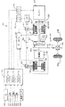
図1は、本発明の一実施形態としてのハイブリッド自動車20の構成の概略を示す構成図である。実施例のハイブリッド自動車20は、図示するように、エンジン22と、エンジン22の出力軸としてのクランクシャフト26にダンパ28を介して接続された3軸式の動力分配統合機構30と、動力分配統合機構30に接続された発電可能なモータMG1と、変速機60を介して動力分配統合機構30に接続されたモータMG2と、車両全体をコントロールするハイブリッド用電子制御ユニット70とを備える。
FIG. 1 is a configuration diagram showing an outline of a configuration of a
エンジン22は、ガソリンまたは軽油などの炭化水素系の燃料により動力を出力する内燃機関であり、エンジン22の運転状態を検出する各種センサから信号を入力するエンジン用電子制御ユニット(以下、エンジンECUという)24により燃料噴射制御や点火制御,吸入空気量調節制御などの運転制御を受けている。エンジンECU24は、ハイブリッド用電子制御ユニット70と通信しており、ハイブリッド用電子制御ユニット70からの制御信号によりエンジン22を運転制御すると共に必要に応じてエンジン22の運転状態に関するデータをハイブリッド用電子制御ユニット70に出力する。
The
動力分配統合機構30は、外歯歯車のサンギヤ31と、このサンギヤ31と同心円上に配置された内歯歯車のリングギヤ32と、サンギヤ31に噛合すると共にリングギヤ32に噛合する複数のピニオンギヤ33と、複数のピニオンギヤ33を自転かつ公転自在に保持するキャリア34とを備え、サンギヤ31とリングギヤ32とキャリア34とを回転要素として差動作用を行なう遊星歯車機構として構成されている。動力分配統合機構30は、キャリア34にはエンジン22のクランクシャフト26が、サンギヤ31にはモータMG1が、リングギヤ32にはリングギヤ軸32aを介して変速機60がそれぞれ連結されており、モータMG1が発電機として機能するときにはキャリア34から入力されるエンジン22からの動力をサンギヤ31側とリングギヤ32側にそのギヤ比に応じて分配し、
モータMG1が電動機として機能するときにはキャリア34から入力されるエンジン22からの動力とサンギヤ31から入力されるモータMG1からの動力を統合してリングギヤ32側に出力する。リングギヤ32に出力された動力は、リングギヤ軸32aからギヤ機構37,デファレンシャルギヤ38を介して駆動輪39a,39bに出力される。
The power distribution and
When the motor MG1 functions as an electric motor, the power from the
モータMG1およびモータMG2は、共に発電機として駆動することができると共に電動機として駆動できる周知の同期発電電動機として構成されており、インバータ41,42を介してバッテリ50と電力のやりとりを行なう。インバータ41,42とバッテリ50とを接続する電力ライン54は、各インバータ41,42が共用する正極母線および負極母線として構成されており、モータMG1,MG2の一方で発電される電力を他のモータで消費することができるようになっている。したがって、バッテリ50は、モータMG1,MG2から生じた電力や不足する電力により充放電されることになる。なお、モータMG1とモータMG2とにより電力収支のバランスをとるものとすれば、バッテリ50は充放電されない。モータMG1,MG2は、共にモータ用電子制御ユニット(以下、モータECUという)40により駆動制御されている。モータECU40には、モータMG1,MG2を駆動制御するために必要な信号、例えばモータMG1,MG2の回転子の回転位置を検出する回転位置検出センサ43,44からの信号や図示しない電流センサにより検出されるモータMG1,MG2に印加される相電流などが入力されており、モータECU40からは、インバータ41,42へのスイッチング制御信号が出力されている。モータECU40は、回転位置検出センサ43,44から入力した信号に基づいて図示しない回転数算出ルーチンによりモータMG1,MG2の回転子の回転数Nm1,Nm2やリングギヤ軸32aの回転数Nrを計算している。モータECU40は、ハイブリッド用電子制御ユニット70と通信しており、ハイブリッド用電子制御ユニット70からの制御信号によってモータMG1,MG2を駆動制御すると共に必要に応じてモータMG1,MG2の運転状態に関するデータをハイブリッド用電子制御ユニット70に出力する。
Both the motor MG1 and the motor MG2 are configured as well-known synchronous generator motors that can be driven as generators and can be driven as motors, and exchange power with the
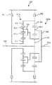
変速機60は、モータMG2の回転軸48とリングギヤ軸32aとの接続および接続の解除を行なうと共に両軸の接続をモータMG2の回転軸48の回転数を2段に減速してリングギヤ軸32aに伝達できるよう構成されている。変速機60の構成の一例を図2に示す。この図2に示す変速機60は、ダブルピニオンの遊星歯車機構60aとシングルピニオンの遊星歯車機構60bと二つのブレーキB1,B2とにより構成されている。ダブルピニオンの遊星歯車機構60aは、外歯歯車のサンギヤ61と、このサンギヤ61と同心円上に配置された内歯歯車のリングギヤ62と、サンギヤ61に噛合する複数の第1ピニオンギヤ63aと、この第1ピニオンギヤ63aに噛合すると共にリングギヤ62に噛合する複数の第2ピニオンギヤ63bと、複数の第1ピニオンギヤ63aおよび複数の第2ピニオンギヤ63bを連結して自転かつ公転自在に保持するキャリア64とを備えており、サンギヤ61はブレーキB1のオンオフによりその回転を自由にまたは停止できるようになっている。シングルピニオンの遊星歯車機構60bは、外歯歯車のサンギヤ65と、このサンギヤ65と同心円上に配置された内歯歯車のリングギヤ66と、サンギヤ65に噛合すると共にリングギヤ66に噛合する複数のピニオンギヤ67と、複数のピニオンギヤ67を自転かつ公転自在に保持するキャリア68とを備えており、サンギヤ65はモータMG2の回転軸48に、キャリア68はリングギヤ軸32aにそれぞれ連結されていると共にリングギヤ66はブレーキB2のオンオフによりその回転が自由にまたは停止できるようになっている。ダブルピニオンの遊星歯車機構60aとシングルピニオンの遊星歯車機構60bとは、リングギヤ62とリングギヤ66、キャリア64とキャリア68とによりそれぞれ連結されている。変速機60は、ブレーキB1,B2を共にオフとすることによりモータMG2の回転軸48をリングギヤ軸32aから切り離すことができ、ブレーキB1をオフとすると共にブレーキB2をオンとしてモータMG2の回転軸48の回転を比較的大きな減速比で減速してリングギヤ軸32aに伝達し(以下、この状態をLoギヤの状態という)、ブレーキB1をオンとすると共にブレーキB2をオフとしてモータMG
2の回転軸48の回転を比較的小さな減速比で減速してリングギヤ軸32aに伝達する(以下、この状態をHiギヤの状態という)。ブレーキB1,B2を共にオンとする状態は回転軸48やリングギヤ軸32aの回転を禁止するものとなる。ブレーキB1,B2のオンオフは、実施例では、図示しない油圧式のアクチュエータの駆動によりブレーキB1,B2に対して作用させる油圧を調節することにより行なわれている。
The
The rotation of the
バッテリ50は、バッテリ用電子制御ユニット(以下、バッテリECUという)52によって管理されている。バッテリECU52には、バッテリ50を管理するのに必要な信号、例えば、バッテリ50の端子間に設置された図示しない電圧センサからの端子間電圧,バッテリ50の出力端子に接続された電力ライン54に取り付けられた図示しない電流センサからの充放電電流,バッテリ50に取り付けられた図示しない温度センサからの電池温度などが入力されており、必要に応じてバッテリ50の状態に関するデータを通信によりハイブリッド用電子制御ユニット70に出力する。なお、バッテリECU52では、バッテリ50を管理するために電流センサにより検出された充放電電流の積算値に基づいて残容量(SOC)も演算している。
The
ハイブリッド用電子制御ユニット70は、CPU72を中心とするマイクロプロセッサとして構成されており、CPU72の他に処理プログラムを記憶するROM74と、データを一時的に記憶するRAM76と、図示しない入出力ポートおよび通信ポートとを備える。ハイブリッド用電子制御ユニット70には、イグニッションスイッチ80からのイグニッション信号,シフトレバー81の操作位置を検出するシフトポジションセンサ82からのシフトポジションSP,アクセルペダル83の踏み込み量に対応したアクセル開度Accを検出するアクセルペダルポジションセンサ84からのアクセル開度Acc,ブレーキペダル85の踏み込み量を検出するブレーキペダルポジションセンサ86からのブレーキペダルポジションBP,車速センサ88からの車速Vなどが入力ポートを介して入力されている。また、ハイブリッド用電子制御ユニット70からは、変速機60のブレーキB1,B2の図示しないアクチュエータへの駆動信号などが出力されている。なお、ハイブリッド用電子制御ユニット70は、前述したように、エンジンECU24やモータECU40,バッテリECU52と通信ポートを介して接続されており、エンジンECU24やモータECU40,バッテリECU52と各種制御信号やデータのやりとりを行なっている。
The hybrid
こうして構成された実施例のハイブリッド自動車20は、運転者によるアクセルペダル83の踏み込み量に対応するアクセル開度Accと車速Vとに基づいて駆動軸としてのリングギヤ軸32aに出力すべき要求トルクを計算し、この要求トルクに対応する要求動力がリングギヤ軸32aに出力されるように、エンジン22とモータMG1とモータMG2とが運転制御される。エンジン22とモータMG1とモータMG2の運転制御としては、要求動力に見合う動力がエンジン22から出力されるようにエンジン22を運転制御すると共にエンジン22から出力される動力のすべてが動力分配統合機構30とモータMG1とモータMG2とによってトルク変換されてリングギヤ軸32aに出力されるようモータMG1およびモータMG2を駆動制御するトルク変換運転モードや要求動力とバッテリ50の充放電に必要な電力との和に見合う動力がエンジン22から出力されるようにエンジン22を運転制御すると共にバッテリ50の充放電を伴ってエンジン22から出力される動力の全部またはその一部が動力分配統合機構30とモータMG1とモータMG2とによるトルク変換を伴って要求動力がリングギヤ軸32aに出力されるようモータMG1およびモータMG2を駆動制御する充放電運転モード、エンジン22の運転を停止してモータMG2からの要求動力に見合う動力をリングギヤ軸32aに出力するよう運転制御するモータ運転モードなどがある。
The
次に、こうして構成された実施例のハイブリッド自動車20の動作について説明する。
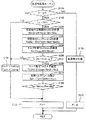
図3は、実施例のハイブリッド自動車20のハイブリッド用電子制御ユニット70により実行される駆動制御ルーチンの一例を示すフローチャートである。このルーチンは、所定時間毎(例えば、8msec毎)に繰り返し実行される。
Next, the operation of the thus configured
FIG. 3 is a flowchart illustrating an example of a drive control routine executed by the hybrid
駆動制御ルーチンが実行されると、ハイブリッド用電子制御ユニット70のCPU72は、まず、アクセルペダルポジションセンサ84からのアクセル開度Accや車速センサ88からの車速V,モータMG1,MG2の回転数Nm1,Nm2,バッテリ50の残容量SOC,バッテリ50の入力制限Win,変速機60の減速比Grなどのデータを入力する処理を実行する(ステップS100)。ここで、モータMG1,MG2の回転数Nm1,Nm2は、回転位置検出センサ43,44により検出されるモータMG1,MG2の回転子の回転位置に基づいて計算されたものをモータECU40から通信により入力するものとした。残容量SOCは、電流センサにより検出されたバッテリ50の充放電電流に基づいて演算されたものをバッテリECU52から通信により入力するものとした。入力制限Winは、残容量SOCや電池温度などに基づいて設定されたものを入力するものとした。なお、入力制限Winは、バッテリ50に入力できる電力が大きくなるほど小さくなるよう符号(マイナス)を定めた。減速比Grは、現在の変速機60のギヤの状態に基づいて設定したものを入力するものとした。
When the drive control routine is executed, first, the
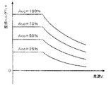
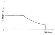
こうしてデータを入力すると、入力したアクセル開度Accと車速Vとに基づいて車両に要求されるトルクとして駆動輪39a,39bに連結された駆動軸としてのリングギヤ軸32aに出力すべき要求トルクTr*と要求パワーPr*を設定する(ステップS102)。要求トルクTr*は、実施例では、アクセル開度Accと車速Vと要求トルクTr*との関係を予め定めて要求トルク設定用マップとしてROM74に記憶しておき、アクセル開度Accと車速Vとが与えられると記憶したマップから対応する要求トルクTr*を導出して設定するものとした。図4に要求トルク設定用のマップの一例を示す。要求パワーPr*は、設定された要求トルクTr*にリングギヤ軸32aの回転数Nrを乗じて計算したものを設定するものとした。ここで、リングギヤ軸32aの回転数Nrは、モータMG2の回転数Nm2に変速機60の減速比Grを除することにより計算することができる。
When the data is input in this way, the required torque Tr * to be output to the
続いて、設定した要求パワーPr*とバッテリ50が充放電すべき充放電要求量Pb*との和によりエンジン要求パワーPe*を設定する(ステップS104)。ここで、充放電要求量Pb*は、バッテリ50の残容量(SOC)やアクセル開度Accなどによって設定することができる。なお、エンジン要求パワーPe*は、説明を容易とするためにロス(Loss)がないものとして計算したが、実際には、ロスを考慮して計算される。
Subsequently, the engine required power Pe * is set by the sum of the set required power Pr * and the charge / discharge request amount Pb * to be charged / discharged by the battery 50 (step S104). Here, the required charge / discharge amount Pb * can be set by the remaining capacity (SOC) of the
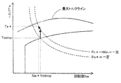
エンジン要求パワーPe*を設定すると、設定したエンジン要求パワーPe*とエンジン22を効率よく動作させる動作ラインとに基づいてエンジン22の仮エンジン回転数Netmpと仮エンジントルクTetmpとを設定する処理を行なう(ステップS106)。エンジン22の動作ラインの一例と仮エンジン回転数Netmpと仮エンジントルクTetmpとを設定する様子を図5に示す。図示するように、仮エンジン回転数Ne*と仮エンジントルクTe*は、動作ラインと目標パワーPe*(Ne*×Te*)が一定の曲線との交点により求めることができる。
When the engine required power Pe * is set, a process of setting the temporary engine speed Nettmp and the temporary engine torque Tempmp of the
次に、変速機60の変速要求がなれているか否かを判定する(ステップS108)。変速要求は、要求トルクTr*と車速Vとに基づいてLoギヤの状態からHiギヤの状態への切替要求やHiギヤの状態からLoギヤの状態への切替要求としてなされる。変速機60の変速要求がなされていないと判定されると、仮エンジン回転数Netmpを目標回転数Ne*として、仮エンジントルクTetmpを目標トルクTe*として設定し(ステップS110)、設定した目標回転数Ne*とリングギヤ軸32aの回転数Nr(=Nm2
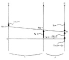
/Gr)と動力分配統合機構30のギヤ比ρとを用いて次式(1)によりモータMG1の目標回転数Nm1*を計算すると共に計算した目標回転数Nm1*と現在の回転数Nm1とに基づいて次式(2)によりモータMG1のトルク指令Tm1*を計算する(ステップS112)。動力分配統合機構30の各回転要素の回転数とトルクの力学的な関係を示す共線図を図6に示す。図中、左のS軸はサンギヤ31の回転数を示し、C軸はキャリア34の回転数を示し、R軸はリングギヤ32(リングギヤ軸32a)の回転数Nrを示す。前述したように、サンギヤ31の回転数はモータMG1の回転数Nm1でありキャリア34の回転数はエンジン22の回転数Neであるから、モータMG1の目標回転数Nm1*はリングギヤ軸32aの回転数Nrとエンジン22の目標回転数Ne*と動力分配統合機構30のギヤ比ρとに基づいて式(1)により計算することができる。したがって、モータMG1が目標回転数Nm1*で回転するよう目標トルクTm1*を設定してモータMG1を駆動制御することにより、エンジン22の目標回転数Ne*で回転させることができる。ここで、式(2)は、モータMG1を目標回転数Nm1*で回転させるためのフィードバック制御における関係式であり、式(2)中、右辺第2項の「KP」は比例項のゲインであり、右辺第3項の「KI」は積分項のゲインである。
Next, it is determined whether or not a shift request for the
/ Gr) and the gear ratio ρ of the power distribution and

モータMG1の目標回転数Nm1*とトルク指令Tm1*とを計算すると、要求トルクTr*とトルク指令Tm1*と動力分配統合機構30のギヤ比ρと変速機60の現在のギヤ比Grとに基づいて次式(3)により要求トルクTr*をリングギヤ軸32aに出力するためにモータMG2から出力すべきトルクとしての仮モータトルクTm2tmpを設定すると共に(ステップS114)、バッテリ50の入力制限WinとモータMG1のトルク指令Tm1*と回転数Nm1と回転数Nm2とに基づいて次式(4)によりモータMG2から出力してもよいトルクの下限としてのトルク制限値Tminを計算し(ステップS116)、仮モータトルクTm2tmpとトルク制限値Tminのうち大きい方をモータMG2のトルク指令Tm2*として設定する(ステップS118)。
When the target rotational speed Nm1 * of the motor MG1 and the torque command Tm1 * are calculated, it is based on the required torque Tr *, the torque command Tm1 *, the gear ratio ρ of the power distribution and
こうしてエンジン22の目標回転数Ne*や目標トルクTe*,モータMG1,MG2のトルク指令Tm1*,Tm2*を設定すると、エンジン22の目標回転数Ne*と目標トルクTe*についてはエンジンECU24に、モータMG1,MG2のトルク指令Tm1*,Tm2*についてはモータECU40にそれぞれ送信して(ステップS120)、駆動制御ルーチンを終了する。目標回転数Ne*と目標トルクTe*とを受信したエンジンECU24は、エンジン22が目標回転数Ne*と目標トルクTe*とにおける運転ポイントで運転されるようにエンジン22における燃料噴射制御や点火制御などの制御を行
なう。また、トルク指令Tm1*,Tm2*を受信したモータECU40は、トルク指令Tm1*でモータMG1が駆動されると共にトルク指令Tm2*でモータMG2が駆動されるようインバータ41,42のスイッチング素子のスイッチング制御を行なう。
Thus, when the target engine speed Ne *, the target torque Te *, and the torque commands Tm1 *, Tm2 * of the motors MG1, MG2 are set, the target engine speed Ne * and the target torque Te * of the
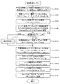
ステップS108で変速機60の変速要求がなされていると判定されると、図7に例示する変速時処理ルーチンを実行することによりエンジン22の目標回転数Ne*と目標トルクTe*とを設定し(ステップS122)、モータMG1,MG2のトルク指令Tm1*,Tm2*を設定すると共にエンジンECU24やモータECU40に送信する処理を行なって(ステップS112〜S120)、本ルーチンを終了する。以下、図7の変速時処理ルーチンの詳細について説明する。変速時処理ルーチンでは、まず、フラグFの値を調べる(ステップS150)。ここで、フラグFは、変速機60における変速段の切替の実行段階を示すフラグであり、初期値として値0が設定されている。即ち、フラグFは、「値0」が変速段の切替前の前処理の段階を意味し、「値1」が変速段の切替時の段階を意味する。
If it is determined in step S108 that a shift request for the
フラグFが値0のときには、変速機60の変速要求がLoギヤの状態からHiギヤの状態への要求であるか否かを判定する(ステップS152)。変速要求がLoギヤの状態からHiギヤの状態への切替要求でないとき、即ちHiギアの状態からLoギヤの状態への切替要求であるときには、図3の駆動制御ルーチンのステップS106で設定された仮エンジン回転数Netmpを目標回転数Ne*として、仮エンジントルクTetmpを目標トルクTe*として設定し(ステップS154)、フラグFを値1に設定して(ステップS156)、処理を終了する。したがって、変速要求がHiギヤの状態からLoギヤの状態への要求であるときには、図3の駆動制御ルーチンのステップS110の処理と同一の処理を行なう。この理由については後述する。
When the flag F is 0, it is determined whether or not the shift request of the
変速機60の変速要求がLoギヤの状態からHiギヤの状態への切替要求であるときには、エンジン22からリングギヤ32側に分配されてリングギヤ軸32aに直接伝達されるトルクが要求トルクTr*に一致するよう次式(5)によりエンジン22の目標トルクTe*を設定し(ステップS158)、設定した目標トルクTe*に仮エンジン回転数Netmpを乗じたもの(=Te*×Netmp)が要求パワーPr*にバッテリ50の入力制限Winを減じたもの(=Pr*−Win)よりも大きいか否かを判定する(ステップS160)。この判定は、仮エンジン回転数Netmpと目標トルクTe*とを用いて制御したときにエンジン22から出力されるパワーが、要求パワーPr*のすべてを賄いながらバッテリ50の入力制限Winの範囲内でエンジン22から出力できるパワーの最大値を越えるか否かを調べるために行なわれるものである。ステップS160で否定的な判定がなされると、バッテリ50の入力制限Winの範囲内であると判断して、仮エンジン回転数Netmpをエンジン22の目標回転数Ne*として設定する(ステップS162)。そして、目標トルクTe*が、仮エンジン回転数Netmpにおいてエンジン22から出力できるトルクの上限としてのトルク上限値Temaxよりも大きいか否かを判定し(ステップS164)、目標トルクTe*がトルク上限値Temaxよりも大きくないと判定されると、そのままフラグFを値1に設定して(ステップS156)、処理を終了し、目標トルクTe*がトルク上限値Temaxよりも大きいと判定されると、ステップS158で設定した目標トルクTe*をトルク上限値Temaxで制限し(ステップS166)、フラグFを値1に設定して(ステップS156)、処理を終了する。
When the shift request of the
![]()
![]()
ステップS160で肯定的な判定がなされると、入力制限Winを越える電力がバッテ
リ50に入力されると判断して、要求パワーPr*に入力制限Winを減じたもの(=Pr*−Win)を目標トルクTe*で除して得られたものをエンジン22の目標回転数Ne*として設定する(ステップS168)。図8に、エンジン22の目標回転数Ne*を設定する様子を示す。前述したように、値Pr*−Winは要求パワーPr*のすべてを賄いながらバッテリ50の入力制限Winの範囲内でエンジン22から出力できるパワーの最大値であるから、仮エンジン回転数Netmpと目標トルクTe*におけるエンジン22のパワーが値Pr*−Winを越えるときには値Pr*−Winが一定の曲線上で目標トルクTe*を出力できる回転数をエンジン22の目標回転数Ne*として設定することにより(図8参照)、目標トルクTe*の出力を確保することができる。目標回転数Ne*を設定すると、ステップS168で設定した目標トルクTe*が、設定した目標回転数Ne*においてエンジン22から出力できるトルクの上限としてのトルク上限値Temaxよりも大きいか否かを判定し(ステップS170)、目標トルクTe*がトルク上限値Temaxよりも大きくないときには、そのままフラグFを値1に設定して(ステップS156)、処理を終了し、目標トルクTe*がトルク上限値Temaxよりも大きいときには、ステップS158やステップS170で設定した目標回転数Ne*と目標トルクTe*を値Pr*−Winが一定の曲線と最大トルクラインとの交点における回転数とトルクに再設定し(ステップS174)、フラグFを値1に設定して(ステップS156)、処理を終了する。これにより、バッテリ50の入力制限Winの範囲内でエンジン22からリングギヤ軸32aに直接伝達されるトルクが要求トルクTr*となるようにエンジン22を制御することができ、モータMG2から出力すべきトルクを略値0とすることができる。
If an affirmative determination is made in step S160, it is determined that power exceeding the input limit Win is input to the
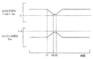
フラグFが値1とされたとき、変速機60の変速段を切り替え、即ち、Loギヤの状態からHiギヤの状態とするときにはブレーキB1がオフでブレーキB2がオンの状態からブレーキB1がオンでブレーキB2がオフの状態に切り替え、Hiギヤの状態からLoギヤの状態とするときにはブレーキB1がオンでブレーキB2がオフの状態からブレーキB1がオフでブレーキB2がオンの状態に切り替え(ステップS174)、フラグFを値0に設定して(ステップS176)、処理を終了する。図9は、変速機60の変速段を切り替える様子を示す説明図である。図9(a)に変速機60をHiギヤの状態からLoギヤの状態に切り替える様子を示し、図9(b)に変速機60をLoギヤの状態からHiギヤの状態へ切り替える様子を示す。また、図10は、変速機60の変速段をLoギヤの状態からHiギヤの状態へ切り替える際の要求トルクTr*のエンジン22の分担分とモータMG2の分担分の時間変化の様子を説明する説明図である。図9に示すように、実施例では、変速機60のHiギヤの状態からLoギヤの状態への切替は、ブレーキB1をスリップ状態かオフとしながら駆動軸(リングギヤ軸32a)の負荷とモータMG2から出力されるトルクとによってリングギヤ62,66の回転数がゼロまで下がったときにブレーキB2をオンとすることにより行ない、変速機60のLoギヤの状態からHiギヤの状態への切替は、ブレーキB2をオンからオフとすると共に駆動軸の負荷とモータMG2から出力されるトルクとによりサンギヤ61に作用するトルクに抗するトルクをブレーキB1のフリクション係合により出力しながらサンギヤ61の回転数を引き上げてゼロに達したときにブレーキB1をオンとすることにより行なうため、Loギヤの状態からHiギヤの状態に切り替える方がブレーキB1による損失が大きくなり変速段の切替時にリングギヤ軸32aへのトルクの落ち込みや変速ショックが大きくなる。したがって、図10に示すように、Loギヤの状態からHiギヤの状態への変速要求がなされると(時刻t1)、入力制限Winの範囲内でできる限り要求トルクTr*をエンジン22からリングギヤ軸32aに直接伝達されるトルクにより賄われるようエンジン22とモータMG1,MG2とを制御し(時刻t2)、その後に変速段の切替を行なう(時刻t3)。この結果、変速段をLoギヤの状態からHiギヤの状態へ切り替える際におけるリングギヤ軸32aへのトルクの落ち込みや変速ショックが抑制される。
When the flag F is set to 1, the gear position of the
以上説明した実施例のハイブリッド自動車20によれば、変速機60の変速要求がLoギヤの状態からHiギヤの状態への切替の要求であるときに、駆動軸としてのリングギヤ軸32aに要求される要求トルクTr*のすべてをモータMG1の発電を伴ってエンジン22からリングギヤ軸32aに直接伝達されるトルクにより賄われるようエンジン22の目標回転数Ne*と目標トルクTe*とを設定して制御するから、変速機60が取り付けられたモータMG2から出力すべきトルクを略値0とした状態でその変速段を切り替えることができる。この結果、変速段を切り替える際のトルクの落ち込みや変速ショックを抑制することができる。もとより、入力制限Winの範囲内で行なうから、バッテリ50の過大な電力による充電や過充電を防止することができる。
According to the
実施例のハイブリッド自動車20では、入力制限Winの範囲内で要求トルクTr*のすべてをエンジン22からリングギヤ軸32aに伝達されるトルクにより賄われるように目標回転数Ne*と目標トルクTe*とを設定したが、エンジン22の分担分を通常時よりも大きくすると共にモータMG2の分担分を小さくできれば、必ずしも要求トルクTr*のすべてをエンジン22からリングギヤ軸32aに伝達されるトルクにより賄う必要はない。この場合、バッテリ50の入力制限Winの範囲内でエンジン要求パワーPe*とエンジン22を効率よく運転できる動作ラインとの交点におけるトルクよりも高トルクを出力できる運転ポイントであれば、如何なる運転ポイントを目標回転数Ne*と目標トルクTe*として設定してもよい。例えば、エンジン要求パワーPe*と動作ラインとの交点における回転数を目標回転数Ne*として設定し、交点におけるトルクに所定値を加算したものを目標トルクTe*として設定するものとしてもよい。
In the
実施例のハイブリッド自動車20では、図7の変速時処理ルーチンのステップS152で変速機60の変速要求がHiギヤの状態からLoギヤの状態への切替要求のときには、変速機60の変速要求がないときと同様に、エンジン要求パワーPe*とエンジン22を効率よく運転する動作ラインとの交点のポイント(仮エンジン回転数Netmpと仮エンジントルクTetmp)を目標回転数Ne*と目標トルクTe*として設定したが、Hiギヤの状態からLoギヤの状態に切り替える場合も若干のトルクの落ち込みや変速ショックは生じるから、この場合も変速機60の変速要求がLoギヤの状態からHiギヤの状態への切替要求であるときと同様に、ステップS158〜S172の処理により目標回転数Ne*と目標トルクTe*とを設定するものとしてもよいし、異なる手法により目標回転数Ne*と目標トルクTe*を設定するものとしてもよい。
In the
実施例のハイブリッド自動車20では、変速機60のギヤの状態を切り替える際には、モータMG2から出力されるパワーを保持しながら変速機60のギヤの状態を切り替える等パワー変速を行なうことができるか否かについては考慮しないものとしたが、これを考慮するものとしてもよい。以下、等パワー変速を行なう際の駆動制御ルーチンについて説明する。
In the
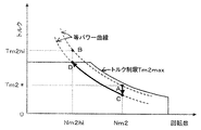
図11に変形例の変速時処理ルーチンの一例の一部を示す。この変速時処理ルーチンは、図7の変速時処理ルーチンのステップS158の処理に代えてステップS200〜S210の処理を実行する点を除いて図7の変速時処理ルーチンと同一である。この変速時処理ルーチンでは、フラグFが値0であり変速機60の変速要求がLoギヤの状態からHiギヤの状態への切替要求であるときには(ステップS150,S152)、現在のモータMG2の回転数Nm2と変速機60がHi,Loギヤの状態のときのギヤ比Ghi,Gloとを用いて変速段の切替後のモータMG2の回転数Nm2hiを次式(6)により計算すると共に(ステップS200)、現在のモータMG2のトルク指令(前回Tm2*)に現在のモータMG2の回転数Nm2を乗じて得られるモータMG2の消費電力(前回Tm2*・Nm2)を切替後の回転数Nm2hiで除することにより等パワー変速を行なった際の切替後のモータMG2のトルクTm2hiを計算し(ステップS202)、切替後のモータMG2の回転数Nm2hiにおける最大定格トルクをモータMG2のトルク制限Tm2maxに設定する(ステップS204)。ここで、トルク制限Tm2maxは、実施例では、モータMG2の回転数Nm2とトルク制限Tm2maxとの関係を予め定めてトルク制限設定用マップとしてROM74に記憶しておき、切替後のモータMG2の回転数Nm2hiが与えられるとマップから対応するトルク制限Tm2maxを導出して設定するものとした。トルク制限設定用マップの一例を図12に示す。続いて、等パワー変速を行なった際の切替後のモータMG2のトルクTm2hiとトルク制限Tm2maxとを比較し(ステップS206)、切替後のモータMG2のトルクTm2hiがトルク制限Tm2max以下のときには、モータMG2から出力されるパワーを保持しながら等パワー変速を行なうことができると判断し、ステップS154以降の処理を実行する。一方、切替後のモータMG2のトルクTm2hiがトルク制限Tm2maxより大きいときには、このままでは等パワー変速を行なうことができないと判断し、切替後の回転数Nm2hiにトルク制限Tm2maxを乗じて得られる等パワー変速を行なった際にモータMG2から出力可能な最大パワー(Tm2max・Nm2hi)を現在のモータMG2の回転数Nm2で除することによりモータMG2のトルク指令Tm2*を設定し(ステップS208)、要求トルクTr*とモータMG2のトルク指令Tm2*と動力分配統合機構30のギヤ比ρとを用いてエンジン22の目標トルクTe*を式(7)により計算し(ステップS210)、ステップS160以降の処理を実行し、図3の駆動制御ルーチンに戻って、ステップS114〜S118の処理によりバッテリ50の入力制限Winで制限した範囲内でモータMG2のトルク指令Tm2*を再設定する。そして、次回に変速時処理ルーチンが実行されたときには、等パワー変速を行なう(ステップS174)。このように、等パワー変速を行なうことができるときにはそのまま等パワー変速を行ない、等パワー変速を行なうことができないときには等パワー変速を行なうことができるようモータMG2のトルク指令Tm2*を調整してから等パワー変速を行なうことにより、等パワー変速を行なう際の駆動軸としてのリングギヤ軸32aに出力されるトルクの落ち込みや変速ショックを抑制することができる。
FIG. 11 shows a part of an example of a shift time processing routine of a modified example. This shift process routine is the same as the shift process routine of FIG. 7 except that the processes of steps S200 to S210 are executed instead of the process of step S158 of the shift process routine of FIG. In this shift time processing routine, when the flag F is 0 and the shift request of the
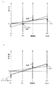
図13に変速機60の変速段をLoギヤの状態からHiギヤの状態に切り替える際の様子を示す。図示するように、点AでモータMG2を駆動制御している最中に変速機60の変速要求がなされたときには、切替後のモータMG2の回転数Nm2hiにおけるトルクTm2hiを計算すると共に(点B参照)、トルク制限Tm2maxを設定する(点D参照)。そして、切替後の回転数Nm2hiにおけるトルクTm2hiがトルク制限Tm2maxより大きいときには、等パワー変速を行なうことができないと判断し、切替後の回転数Nm2におけるトルクTm2hiがトルク制限Tm2maxとなるよう、即ち電動機から出力されるパワーが等パワー変速を行なった際にモータMG2から出力可能な最大パワー(Tm2max・Nm2hi)となるよう現在の回転数Nm2を変更することなくトルクを減少させて点CでモータMG2を駆動制御し、その後に点Cから点Dに等パワー変速を行なう。これにより、等パワー変速を行なっている際に駆動軸としてのリングギヤ軸32aに出力されるトルクの落ち込みや変速ショックを抑制することができる。
FIG. 13 shows a state in which the gear position of the
このように、変形例の図11に例示する変速時処理ルーチンでは、変速機60の変速要求がLoギヤの状態からHiギヤの状態への切替の要求であるときには、等パワー変速を行なうことができるときにはそのまま等パワー変速を行ない、等パワー変速を行なうことができないときには等パワー変速を行なうことができるようモータMG2のトルク指令Tm2*を調整してから等パワー変速を行なうから、等パワー変速を行なう際の駆動軸としてのリングギヤ軸32aに出力されるトルクの落ち込みや変速ショックを抑制することができる。しかも、等パワー変速を行なうことができないときには、等パワー変速を行なった際にモータMG2から出力可能な最大パワーにモータMG2から出力されるパワーがなるようモータMG2のトルク指令Tm2*を調整するから、モータMG2のトルク指令Tm2*の調整をより容易に行なうことができる。
As described above, in the shift process routine illustrated in FIG. 11 of the modified example, when the shift request of the
変形例のハイブリッド自動車20では、変速機60の変速段をLoギヤの状態からHiギヤの状態に切り替えるときにだけ等パワー変速を行なうことができるか否かを判定するものとしたが、Hiギヤの状態からLoギヤの状態に切り替えるときにも等パワー変速を行なうことができるか否かを判定するものとしてもよい。
In the
変形例のハイブリッド自動車20では、等パワー変速を行なうことができないときには、モータMG2から出力されるパワーが等パワー変速を行なうことができる最大パワーになるようモータMG2のトルク指令Tm2*を調整するものとしたが、最大パワーに限られず、モータMG2から出力されるパワーが等パワー変速を行なうことができるパワーとなるよう調整するものであればよい。
In the
実施例のハイブリッド自動車20では、変速機60としてLoギヤの状態とHiギヤの状態とを切り替える2段の変速段をもつものとしたが、3段以上の変速段をもつものとしてもよいし、こうした有段変速機に限られず、無段変速機としてもよい。
In the
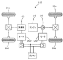
実施例のハイブリッド自動車20では、エンジン22からの動力をモータMG1が接続された動力分配統合機構30を介して駆動輪39a,39bに接続された駆動軸としてのリングギヤ軸32aに出力するものに適用したが、図14の変形例のハイブリッド自動車120に例示するように、エンジン22からの動力を、エンジン22のクランクシャフト26に接続されたインナーロータ132と駆動輪39a,39bに動力を出力する駆動軸に接続されたアウターロータ134とを有しエンジン22の動力の一部を駆動軸に伝達すると共に残余の動力を電力に変換する対ロータ電動機130を介して駆動輪39a,39bに出力するものに適用するものとしてもよい。
The
また、実施例のハイブリッド自動車20では、モータMG2の回転軸を、駆動輪39a,39bに接続された駆動軸に変速機60を介して接続するものとしたが、図15の変形例のハイブリッド自動車220に例示するように、モータMG2の回転軸を、駆動輪39a,39bとは異なる駆動輪39c,39dに接続された駆動軸に変速機60を介して接
続するものとしても構わない。また、これに加えて、駆動輪39a,39bに接続された駆動軸にモータを接続するものとしても構わない。
Further, in the
以上、本発明を実施するための最良の形態について実施例を用いて説明したが、本発明はこうした実施例に何等限定されるものではなく、本発明の要旨を逸脱しない範囲内において、種々なる形態で実施し得ることは勿論である。 The best mode for carrying out the present invention has been described with reference to the embodiments. However, the present invention is not limited to these embodiments, and various modifications can be made without departing from the gist of the present invention. Of course, it can be implemented in the form.
20,120,220 ハイブリッド自動車、22 エンジン、24 エンジン用電子制御ユニット(エンジンECU)、26 クランクシャフト、28 ダンパ、30 動力分配統合機構、31 サンギヤ、32 リングギヤ、32a リングギヤ軸、33 ピニオンギヤ、34 キャリア、36 ベルト、37 ギヤ機構、38 デファレンシャルギヤ、39a,39b 駆動輪、40 モータ用電子制御ユニット(モータECU)、41,42 インバータ、43,44 回転位置検出センサ、48 回転軸、50 バッテリ、52 バッテリ用電子制御ユニット(バッテリECU)、54 電力ライン、60 変速機、60a ダブルピニオンの遊星歯車機構、60b シングルピニオンの遊星歯車機構、61 サンギヤ、62 リングギヤ、63a 第1ピニオンギヤ、63b 第2ピニオンギヤ、64キャリア、65 サンギヤ、66 リングギヤ、67 ピニオンギヤ、68 キャリア、70 ハイブリッド用電子制御ユニット、72 CPU、74 ROM、76 RAM、80 イグニッションスイッチ、81 シフトレバー、82 シフトポジションセンサ、83 アクセルペダル、84 アクセルペダルポジションセンサ、85 ブレーキペダル、86 ブレーキペダルポジションセンサ、88 車速センサ、130 対ロータ電動機、132 インナーロータ、134 アウターロータ、MG1,MG2 モータ、B1,B2 ブレーキ。
20, 120, 220 Hybrid vehicle, 22 engine, 24 engine electronic control unit (engine ECU), 26 crankshaft, 28 damper, 30 power distribution integration mechanism, 31 sun gear, 32 ring gear, 32a ring gear shaft, 33 pinion gear, 34 carrier , 36 belt, 37 gear mechanism, 38 differential gear, 39a, 39b drive wheel, 40 motor electronic control unit (motor ECU), 41, 42 inverter, 43, 44 rotational position detection sensor, 48 rotational shaft, 50 battery, 52 Battery electronic control unit (battery ECU), 54 power line, 60 transmission, 60a planetary gear mechanism of double pinion, 60b planetary gear mechanism of single pinion, 61 sun gear, 62 ring gear,
Claims (12)
前記内燃機関の出力軸と前記駆動軸とに接続され、該内燃機関からの動力の少なくとも一部を電力に変換すると共に残余の動力を該駆動軸に伝達可能な電力変換動力伝達手段と、
動力を入出力可能な電動機と、
変更可能な変速比をもって前記電動機と前記駆動軸との間の動力の伝達を行なう変速伝達手段と、
前記電力変換動力伝達手段および前記電動機と電力のやり取りが可能な蓄電手段と、
前記駆動軸に要求される要求駆動力に基づいて前記内燃機関から出力すべき目標動力を設定する目標動力設定手段と、
該設定された目標動力と前記内燃機関に適用した条件とに基づいて該内燃機関の動作点を設定し、該設定した動作点で該内燃機関が運転されると共に前記要求駆動力に対応する駆動力が前記駆動軸に出力されるよう前記内燃機関と前記電力変換動力伝達手段と前記電動機とを駆動制御する駆動制御手段と、
前記変速伝達手段における変速比の切替が指示されたとき、前記駆動制御手段に代えて、前記設定された目標動力に基づいて前記蓄電手段の入力制限の範囲内で該駆動制御手段により設定される動作点とは異なる動作点を設定し、該設定した動作点で前記内燃機関が運転されると共に前記要求駆動力に対応する駆動力が前記駆動軸に出力されるよう前記内燃機関と前記電力変換動力伝達手段と前記電動機とを駆動制御し、前記設定した動作点で前記内燃機関を運転させた後に前記変速伝達手段における変速比が切り替えられるよう該変速伝達手段を駆動制御する変速切替時駆動制御手段と
を備える動力伝達装置。 A power transmission device capable of transmitting power from an internal combustion engine to a drive shaft,
Power conversion power transmission means connected to the output shaft and the drive shaft of the internal combustion engine, capable of converting at least part of the power from the internal combustion engine into electric power and transmitting the remaining power to the drive shaft;
An electric motor that can input and output power;
Shift transmission means for transmitting power between the electric motor and the drive shaft with a changeable gear ratio;
Power storage means capable of exchanging power with the power conversion power transmission means and the electric motor;
Target power setting means for setting target power to be output from the internal combustion engine based on a required driving force required for the drive shaft;
An operating point of the internal combustion engine is set based on the set target power and a condition applied to the internal combustion engine, and the internal combustion engine is operated at the set operating point and a drive corresponding to the required driving force Drive control means for drivingly controlling the internal combustion engine, the power conversion power transmission means, and the electric motor so that force is output to the drive shaft;
When switching of the transmission gear ratio in the transmission transmission unit is instructed, instead of the drive control unit, it is set by the drive control unit within the range of the input limit of the power storage unit based on the set target power. An operating point different from the operating point is set, and the internal combustion engine and the power conversion are operated so that the internal combustion engine is operated at the set operating point and a driving force corresponding to the required driving force is output to the driving shaft. Drive control at the time of shift switching that controls driving of the power transmission means and the electric motor, and drives the transmission transmission means so that the gear ratio in the transmission transmission means is switched after the internal combustion engine is operated at the set operating point. A power transmission device comprising:
(a)前記駆動軸に要求される要求駆動力に基づいて前記内燃機関から出力すべき目標動力を設定し、
(b)該設定された目標動力と前記内燃機関に適用した条件とに基づいて該内燃機関の動作点を設定し、該設定した動作点で該内燃機関が運転されると共に前記要求駆動力に対応する駆動力が前記駆動軸に出力されるよう前記内燃機関と前記電力変換動力伝達手段と前記電動機とを駆動制御し、
(c)前記変速伝達手段における変速比の切替が指示されたとき、前記ステップ(b)に代えて、前記設定された目標動力に基づいて前記蓄電手段の入力制限の範囲内で該ステップ(b)により設定される動作点とは異なる動作点を設定し、該設定した動作点で前記内燃機関が運転されると共に前記要求駆動力に対応する駆動力が前記駆動軸に出力されるよう前記内燃機関と前記電力変換動力伝達手段と前記電動機とを駆動制御し、前記設定した動作点で前記内燃機関を運転させた後に前記変速伝達手段における変速比が切り替えられるよう該変速伝達手段を駆動制御する
動力出力装置の制御方法。 An internal combustion engine, and power conversion power transmission means connected to the output shaft and drive shaft of the internal combustion engine for converting at least part of the power from the internal combustion engine into electric power and transmitting the remaining power to the drive shaft An electric motor capable of inputting / outputting power; transmission transmission means for transmitting power between the electric motor and the drive shaft with a changeable gear ratio; and exchange of electric power with the power conversion power transmission means and the electric motor. A power output device comprising a possible power storage means,
(A) setting a target power to be output from the internal combustion engine based on a required driving force required for the driving shaft;
(B) An operating point of the internal combustion engine is set based on the set target power and a condition applied to the internal combustion engine, the internal combustion engine is operated at the set operating point, and the required driving force is set. Driving and controlling the internal combustion engine, the power conversion power transmission means and the electric motor so that a corresponding driving force is output to the driving shaft;
(C) When switching of the transmission gear ratio in the transmission transmission means is instructed, instead of the step (b), the step (b) within the range of the input limitation of the power storage means based on the set target power The internal combustion engine is operated at the set operating point and the driving force corresponding to the required driving force is output to the driving shaft. Drive control of the engine, the power conversion power transmission means and the electric motor, and drive control of the transmission transmission means so that the gear ratio in the transmission transmission means is switched after the internal combustion engine is operated at the set operating point. Control method of power output device.
Priority Applications (1)
| Application Number | Priority Date | Filing Date | Title |
|---|---|---|---|
| JP2005009196A JP4176080B2 (en) | 2004-03-16 | 2005-01-17 | POWER TRANSMISSION DEVICE, POWER OUTPUT DEVICE, AUTOMOBILE MOUNTING THE SAME, CONTROL METHOD FOR POWER OUTPUT DEVICE |
Applications Claiming Priority (2)
| Application Number | Priority Date | Filing Date | Title |
|---|---|---|---|
| JP2004074787 | 2004-03-16 | ||
| JP2005009196A JP4176080B2 (en) | 2004-03-16 | 2005-01-17 | POWER TRANSMISSION DEVICE, POWER OUTPUT DEVICE, AUTOMOBILE MOUNTING THE SAME, CONTROL METHOD FOR POWER OUTPUT DEVICE |
Publications (2)
| Publication Number | Publication Date |
|---|---|
| JP2005297948A true JP2005297948A (en) | 2005-10-27 |
| JP4176080B2 JP4176080B2 (en) | 2008-11-05 |
Family
ID=35329990
Family Applications (1)
| Application Number | Title | Priority Date | Filing Date |
|---|---|---|---|
| JP2005009196A Expired - Fee Related JP4176080B2 (en) | 2004-03-16 | 2005-01-17 | POWER TRANSMISSION DEVICE, POWER OUTPUT DEVICE, AUTOMOBILE MOUNTING THE SAME, CONTROL METHOD FOR POWER OUTPUT DEVICE |
Country Status (1)
| Country | Link |
|---|---|
| JP (1) | JP4176080B2 (en) |
Cited By (9)
| Publication number | Priority date | Publication date | Assignee | Title |
|---|---|---|---|---|
| WO2008084766A1 (en) * | 2007-01-10 | 2008-07-17 | Toyota Jidosha Kabushiki Kaisha | Controller of power transmission device for vehicle |
| DE112008000504T5 (en) | 2007-02-28 | 2010-01-07 | Toyota Jidosha Kabushiki Kaisha | Control device for a hybrid drive system |
| JP2011116249A (en) * | 2009-12-03 | 2011-06-16 | Toyota Motor Corp | Hybrid vehicle |
| JP2011183974A (en) * | 2010-03-10 | 2011-09-22 | Toyota Motor Corp | Control device for power transmission device |
| US8177005B2 (en) | 2006-03-08 | 2012-05-15 | Toyota Jidosha Kabushiki Kaisha | Vehicle, driving device and control method thereof |
| CN103282257A (en) * | 2010-10-26 | 2013-09-04 | 日产自动车株式会社 | Drive torque control device for hybrid vehicle |
| JP2013244786A (en) * | 2012-05-24 | 2013-12-09 | Toyota Motor Corp | Hybrid vehicle |
| JPWO2012090263A1 (en) * | 2010-12-27 | 2014-06-05 | トヨタ自動車株式会社 | Hybrid vehicle |
| WO2016199813A1 (en) * | 2015-06-09 | 2016-12-15 | 株式会社豊田自動織機 | Power control device |
-
2005
- 2005-01-17 JP JP2005009196A patent/JP4176080B2/en not_active Expired - Fee Related
Cited By (13)
| Publication number | Priority date | Publication date | Assignee | Title |
|---|---|---|---|---|
| US8177005B2 (en) | 2006-03-08 | 2012-05-15 | Toyota Jidosha Kabushiki Kaisha | Vehicle, driving device and control method thereof |
| DE112008000101T5 (en) | 2007-01-10 | 2010-02-04 | Toyota Jidosha Kabushiki Kaisha, Toyota-shi | Control unit for a vehicle power transmission system |
| WO2008084766A1 (en) * | 2007-01-10 | 2008-07-17 | Toyota Jidosha Kabushiki Kaisha | Controller of power transmission device for vehicle |
| US8172018B2 (en) | 2007-01-10 | 2012-05-08 | Toyota Jidosha Kabushiki Kaisha | Control apparatus for vehicular power transmitting system |
| DE112008000504T5 (en) | 2007-02-28 | 2010-01-07 | Toyota Jidosha Kabushiki Kaisha | Control device for a hybrid drive system |
| US8528676B2 (en) | 2007-02-28 | 2013-09-10 | Toyota Jidosha Kabushiki Kaisha | Control apparatus for hybrid drive system |
| JP2011116249A (en) * | 2009-12-03 | 2011-06-16 | Toyota Motor Corp | Hybrid vehicle |
| JP2011183974A (en) * | 2010-03-10 | 2011-09-22 | Toyota Motor Corp | Control device for power transmission device |
| CN103282257A (en) * | 2010-10-26 | 2013-09-04 | 日产自动车株式会社 | Drive torque control device for hybrid vehicle |
| CN103282257B (en) * | 2010-10-26 | 2016-02-24 | 日产自动车株式会社 | The driving torque control setup of motor vehicle driven by mixed power |
| JPWO2012090263A1 (en) * | 2010-12-27 | 2014-06-05 | トヨタ自動車株式会社 | Hybrid vehicle |
| JP2013244786A (en) * | 2012-05-24 | 2013-12-09 | Toyota Motor Corp | Hybrid vehicle |
| WO2016199813A1 (en) * | 2015-06-09 | 2016-12-15 | 株式会社豊田自動織機 | Power control device |
Also Published As
| Publication number | Publication date |
|---|---|
| JP4176080B2 (en) | 2008-11-05 |
Similar Documents
| Publication | Publication Date | Title |
|---|---|---|
| JP4200988B2 (en) | Hybrid vehicle and control method thereof | |
| JP4227998B2 (en) | VEHICLE, DRIVE DEVICE, AND CONTROL METHOD THEREOF | |
| JP2006118359A (en) | Vehicle and control method thereof | |
| JP2006077600A (en) | Power output apparatus, automobile equipped with the same, and control method of power output apparatus | |
| JP4176080B2 (en) | POWER TRANSMISSION DEVICE, POWER OUTPUT DEVICE, AUTOMOBILE MOUNTING THE SAME, CONTROL METHOD FOR POWER OUTPUT DEVICE | |
| JP4254635B2 (en) | Power output apparatus, automobile equipped with the same, and control method of power output apparatus | |
| JP4209375B2 (en) | Power output apparatus, automobile equipped with the same, and control method of power output apparatus | |
| JP4222332B2 (en) | Hybrid vehicle and control method thereof | |
| JP2005151620A (en) | Power output apparatus, automobile equipped with the same, and control method of power output apparatus | |
| JP4217234B2 (en) | POWER OUTPUT DEVICE, AUTOMOBILE MOUNTING THE SAME, DRIVE DEVICE, AND CONTROL METHOD FOR POWER OUTPUT DEVICE | |
| JP4030532B2 (en) | POWER OUTPUT DEVICE, AUTOMOBILE MOUNTING THE SAME, DRIVE DEVICE, AND CONTROL METHOD FOR POWER OUTPUT DEVICE | |
| JP3998002B2 (en) | Hybrid vehicle and control method thereof | |
| JP4182028B2 (en) | POWER OUTPUT DEVICE, AUTOMOBILE MOUNTING THE SAME, DRIVE DEVICE, AND CONTROL METHOD FOR POWER OUTPUT DEVICE | |
| JP4165492B2 (en) | Power output apparatus, automobile equipped with the same, and control method of power output apparatus | |
| JP3962391B2 (en) | Hybrid vehicle power output device, hybrid vehicle, and hybrid vehicle power output device control method | |
| JP2006014387A (en) | Power output apparatus, automobile equipped with the same, and control method of power output apparatus | |
| JP2007112291A (en) | POWER OUTPUT DEVICE, VEHICLE MOUNTING THE SAME, AND METHOD FOR CONTROLLING POWER OUTPUT DEVICE | |
| JP4031773B2 (en) | Power output apparatus, automobile equipped with the same, and control method of power output apparatus | |
| JP4038190B2 (en) | POWER OUTPUT DEVICE, AUTOMOBILE MOUNTED WITH THE SAME, CONTROL METHOD AND DRIVE DEVICE FOR POWER OUTPUT DEVICE | |
| JP2006144843A (en) | Automobile and control method thereof | |
| JP4054005B2 (en) | Power output apparatus, automobile equipped with the same, and control method of power output apparatus | |
| JP2005333713A (en) | Power output device, automobile equipped with the same, power transmission device, and control method for power output device | |
| JP4165491B2 (en) | Power output apparatus, automobile equipped with the same, and control method of power output apparatus | |
| JP4196961B2 (en) | Power output apparatus, automobile equipped with the same, and control method therefor | |
| JP4241707B2 (en) | Vehicle and control method thereof |
Legal Events
| Date | Code | Title | Description |
|---|---|---|---|
| A711 | Notification of change in applicant |
Free format text: JAPANESE INTERMEDIATE CODE: A711 Effective date: 20061004 |
|
| A621 | Written request for application examination |
Free format text: JAPANESE INTERMEDIATE CODE: A621 Effective date: 20070829 |
|
| A131 | Notification of reasons for refusal |
Free format text: JAPANESE INTERMEDIATE CODE: A132 Effective date: 20080603 |
|
| A521 | Request for written amendment filed |
Free format text: JAPANESE INTERMEDIATE CODE: A523 Effective date: 20080714 |
|
| TRDD | Decision of grant or rejection written | ||
| A01 | Written decision to grant a patent or to grant a registration (utility model) |
Free format text: JAPANESE INTERMEDIATE CODE: A01 Effective date: 20080812 |
|
| A01 | Written decision to grant a patent or to grant a registration (utility model) |
Free format text: JAPANESE INTERMEDIATE CODE: A01 |
|
| A61 | First payment of annual fees (during grant procedure) |
Free format text: JAPANESE INTERMEDIATE CODE: A61 Effective date: 20080819 |
|
| FPAY | Renewal fee payment (event date is renewal date of database) |
Free format text: PAYMENT UNTIL: 20110829 Year of fee payment: 3 |
|
| LAPS | Cancellation because of no payment of annual fees |