JP2005297931A - Crew protection device - Google Patents
Crew protection device Download PDFInfo
- Publication number
- JP2005297931A JP2005297931A JP2004132915A JP2004132915A JP2005297931A JP 2005297931 A JP2005297931 A JP 2005297931A JP 2004132915 A JP2004132915 A JP 2004132915A JP 2004132915 A JP2004132915 A JP 2004132915A JP 2005297931 A JP2005297931 A JP 2005297931A
- Authority
- JP
- Japan
- Prior art keywords
- seat
- collision
- vehicle
- sensor
- piston
- Prior art date
- Legal status (The legal status is an assumption and is not a legal conclusion. Google has not performed a legal analysis and makes no representation as to the accuracy of the status listed.)
- Pending
Links
Images
Landscapes
- Seats For Vehicles (AREA)
- Automotive Seat Belt Assembly (AREA)
Abstract
【課題】衝突時にシートを移動させる乗員保護装置においてシートの移動を確保するためにシート設計に影響を及ぼすことを減少する。
【解決手段】衝突予知センサ10と、衝突検出センサ6と、前席用アクチュエータ7とを有し、前面衝突予知を検出したら前席用アクチュエータによりシート2を車両前方に移動させ、衝突を検出したらシートを車両後方に移動させる。衝突前のシートの位置にかかわらず、シートの後方移動量を確保することができる。例えば衝突時のシート後方移動による乗員における衝撃力の緩和に有効な所定長を予め移動させる長さとしておくことにより、衝突時の有効なシート後方移動量を確保することができる。
【選択図】図4In an occupant protection device that moves a seat at the time of a collision, the influence on the seat design to ensure the movement of the seat is reduced.
A collision prediction sensor, a collision detection sensor, and a front seat actuator are detected. When a front collision prediction is detected, a seat is moved forward by the front seat actuator and a collision is detected. Move the seat to the rear of the vehicle. Regardless of the position of the sheet before the collision, it is possible to ensure the amount of backward movement of the sheet. For example, an effective amount of rearward movement of the seat at the time of collision can be ensured by setting the predetermined length effective for mitigating the impact force on the occupant due to the rearward movement of the seat at the time of collision to a length that moves in advance.
[Selection] Figure 4
Description
本発明は、前面衝突時にシートを車両後方に移動させるようにした乗員保護装置に関するものである。 The present invention relates to an occupant protection device that moves a seat to the rear of a vehicle when a frontal collision occurs.
従来、前面衝突時に乗員の慣性力による大きな前方飛び出しによる災害を防止するために、衝突検出センサと前席シート後方移動装置とを設けて、衝突を検出したら前席シートを後方に下げて、衝突時の前方飛び出しを抑制するようにした乗員保護装置がある(例えば、特許文献1参照。)。このようにすることにより、衝突時に乗員に作用する前方への慣性力の増加を打ち消し、早期に車体とシートおよび乗員との減速度を互いに略等しくすることができるため、衝突時における乗員減速度の好適な低減を実現し得る。 Conventionally, in order to prevent a disaster caused by a large forward jump due to the inertial force of the occupant at the time of a frontal collision, a collision detection sensor and a front seat seat rearward movement device have been provided. There is an occupant protection device that suppresses forward jumping of time (see, for example, Patent Document 1). By doing so, it is possible to cancel the increase in forward inertial force acting on the occupant during the collision and to make the deceleration of the vehicle body, the seat and the occupant almost equal to each other at an early stage. Can be realized.
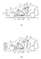
上記乗員保護装置にあっては、例えば図8(a)に示されるように車体フレームにより形成されたフロア4にレール5を介してシート2を移動可能に設けると共に、フロア4と前席シート2との間にアクチュエータ7を設けかつそのピストンロッド7aをシート2に結合している。また、前席シート2にシートベルトアンカーを一体的に設け、例えばエアバッグ装置と共通の衝突検出センサ6を適所に設けている。その動作にあっては、図8(b)に示されるように車両1の前面衝突を衝突検出センサ12で検出したらアクチュエータ7により前席シート2を後方(矢印B方向)へ移動させる。そのシート2の後方移動時にはシートベルトアンカーも後方に移動するため、乗員をシートベルトで拘束して前席シート2に一体化した状態で後方移動させることができる。これにより、乗員に対する負荷を前席シート2の後方移動でコントロールすることができる。
上記したように衝突時に前席シートを後方へ移動させる場合には、前席シートの後方移動による後席スペースの減少による後席乗員や荷物との干渉、シート移動量確保のためのスライドレンジの拡張などを考慮する必要がある。後席スペースの減少に対しては前席シートに緩衝機能を追加することで対応でき、スライドレンジの拡張に対してはスライドレールの伸長にて対応できる。 As described above, when the front seat is moved rearward in the event of a collision, the rear seat is moved backwards to reduce the rear seat space, thereby causing interference with the rear seat occupant and luggage, and a slide range for securing the seat movement amount. It is necessary to consider expansion. The reduction of the rear seat space can be dealt with by adding a buffer function to the front seat, and the extension of the slide range can be dealt with by extending the slide rail.
しかしながら、上記対応はシートの設計に影響を与えるため、その影響を低減することが望まれる。また、後席シートを折り畳むシートアレンジを可能にしたものにおいて折り畳んだ状態の後席シートにより前席シートの後方への移動量が減少する場合もあるという問題がある。 However, since the above-mentioned correspondence affects the design of the sheet, it is desired to reduce the influence. In addition, there is a problem that the amount of movement of the front seats to the rear may be reduced by the rear seats in a folded state in which the seat arrangement for folding the rear seats is possible.
このような課題を解決して、衝突時にシートを移動させる乗員保護装置においてシートの移動を確保するためにシート設計に影響を及ぼすことを減少することを実現するために本発明に於いては、車両(1)の前後方向の少なくともいずれか一方の衝突を予知する衝突予知センサ(10)と、前記車両が前後方向衝突したことを検出する衝突検出センサ(6)と、シート(2)を車両前後方向へ移動させるシート移動装置(7・12)とを有し、前記シート移動装置(7・12)により前記シート(2)を、前記衝突予知センサ(10)による衝突予知信号に応じて予知された車両衝突方向に予め移動させてから、前記衝突検出センサ(6)による衝突検出信号に応じて前記予め移動させた方向とは逆向きに移動させるようにした。特に、前記衝突予知信号に応じてシートベルト(16)の伸び出しを規制するシートベルト規制手段(14)を有すると良い。 In the present invention, in order to solve such a problem, in the occupant protection device that moves the seat at the time of collision, to reduce the influence on the seat design in order to ensure the movement of the seat, A collision prediction sensor (10) for predicting at least one collision in the front-rear direction of the vehicle (1), a collision detection sensor (6) for detecting that the vehicle has collided in the front-rear direction, and a seat (2) A sheet moving device (7, 12) that moves in the front-rear direction, and the sheet moving device (7, 12) predicts the seat (2) according to a collision prediction signal from the collision prediction sensor (10). The vehicle is moved in the vehicle collision direction in advance, and then moved in the direction opposite to the previously moved direction in accordance with a collision detection signal from the collision detection sensor (6). In particular, it is preferable to have a seat belt regulating means (14) for regulating the extension of the seat belt (16) according to the collision prediction signal.
このように本発明によれば、例えば車両の前方向への衝突時には、その衝突予知信号により予めシートを前方に移動してから衝突検出信号に応じてシートを後方へ移動させることから、衝突前のシートの位置にかかわらず、シートの後方移動量を確保することができる。例えば衝突時のシート後方移動による乗員における衝撃力の緩和に有効な所定長を予め移動させる長さとしておくことにより、衝突時の有効なシート後方移動量を確保することができる。 As described above, according to the present invention, for example, when a vehicle collides in the forward direction, the seat is moved forward in accordance with the collision prediction signal and then the seat is moved backward in accordance with the collision detection signal. Regardless of the position of the sheet, the rearward movement amount of the sheet can be secured. For example, an effective amount of rearward movement of the seat at the time of collision can be ensured by setting the predetermined length effective for mitigating the impact force on the occupant due to the rearward movement of the seat at the time of collision to a length that moves in advance.
特に、衝突予知によるシート移動時にシートベルトの伸び出しを規制することにより、シートベルトのたるみを除去すると共にシートベルトの張力を高めることができ、衝突時のシート後方移動における乗員のシートとの一体化により、衝突時の乗員に対する負荷のコントロールをより一層確実なものとすることができる。 In particular, by restricting the extension of the seat belt during the movement of the seat due to the collision prediction, it is possible to remove the slack of the seat belt and increase the tension of the seat belt. As a result, it is possible to further ensure the control of the load on the passenger at the time of the collision.
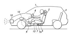
以下、本発明の実施の形態を、図面を参照しながら説明する。図1は、本発明に基づく車体構造を示す概念的な側面図である。図に示されるように、車両1の車室内には前席シート2と後席シート3とが配設されており、車体フレームにより形成されたフロア4の上面に固設されたレール5の上に前席シート2が車両前後方向に移動可能に支持されている。
Hereinafter, embodiments of the present invention will be described with reference to the drawings. FIG. 1 is a conceptual side view showing a vehicle body structure according to the present invention. As shown in the figure, a
なお、前席シート2を前後位置調整可能な構造とした場合には、上記レール5の上にシート位置調整用レールの固定側を載置し、シート位置調整用固定側レールをレール5に対して通常走行時の加減速度では移動しないがそれ以上の大きな力が作用した場合には移動し得るように両者を摩擦係合させるなどすれば良い。あるいはシェアピンを設けるなどしても良い。なお、前席シート2は、シートベルトアンカー及びシートベルト巻き取り装置を一体的に取り付けられたシートベルト一体型であると良い。
When the
車両1の任意の位置には衝突検出センサ(SSR)6が設けられている。衝突検出センサ6は、車両1の前面衝突時の衝撃を減速度の変化で検出するものであって良く、例えば減速度センサからなる。なお、衝突検出センサ6により衝突を検出した場合にはエアバッグを膨張させるようになっている。
A collision detection sensor (SSR) 6 is provided at an arbitrary position of the vehicle 1. The
フロア4には、シート移動装置としての例えばピストン・シリンダ型の前席用アクチュエータ7のシリンダ部分が固定されており、前席用アクチュエータ7のピストンロッド7aの突出方向端部が前席シート2の下部に結合されている。なお、前席シート2が上記したシート位置調整機構を有する場合には、その固定側レールにピストンロッド7aが結合されていれば良い。
For example, a cylinder portion of a piston / cylinder type
なお、前席用アクチュエータ7は、ピストンロッド7aを車両前後方向へ変位させるように作動するものであれば良く、例えば複動型油圧シリンダやリニア駆動モータからなるものであって良い。リニア駆動モータの場合には、ウォームホイール機構やボールねじ機構などが考えられる。
The
車両の前部の任意の位置には衝突予知センサ10が設けられている。衝突予知センサ10は、例えばレーザ式・レーダ式・超音波式などの距離センサであって良く、検出波を車両前方に発し、その反射波により前方障害物を検出して前面衝突することを予知するものである。また、カメラを用いた画像認識によるものであっても良い。
A
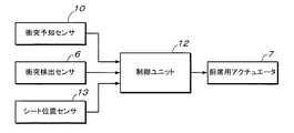
また、図2に示されるように、上記衝突検出センサ6及び衝突予知センサ10の各信号が制御ユニット12に入力され、各信号に応じて制御ユニット12から前席用アクチュエータ7に駆動信号が出力されるようになっている。また、前席用アクチュエータ7には前席シート2の位置を検出するための例えばリミットスイッチであって良いシート位置センサ13が設けられており、例えば前席シート2が移動範囲の前端から車両後方側へ所定距離の位置に位置している(初期位置)か否かをシート位置センサ13により検出する。シート位置センサ13による位置検出信号も制御ユニット12に出力される。それら各検出信号に応じて、制御ユニット12から前席用アクチュエータ7に駆動信号が出力される。
Further, as shown in FIG. 2, the signals of the
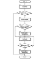
このように構成された車両用乗員保護装置における作動要領について、図3のフロー図を参照して以下に示す。ステップST1では、衝突予知センサ10により前進走行中に前方の障害物に対する検出を行い(衝突予測)、次のステップST2では、車両前面が障害物に衝突することを予知(例えば障害物と車両との衝突が避けられない状況)したか否かを判別する。衝突を予知したと判断した場合にはステップST3に進み、衝突を予知していないと判断した場合には本フローを終了する。
An operation procedure in the vehicle occupant protection device configured as described above will be described below with reference to the flowchart of FIG. In step ST1, the front obstacle is detected by the
ステップST3ではシート位置センサ13の検出信号をチェックし、次のステップST4では前席シート2の位置が初期位置か否かを上記したシート位置センサ13の検出信号に基づいて判別する。前席シート2が初期位置であると判断された場合にはステップST5に進む。
In step ST3, the detection signal of the
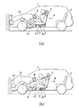
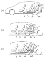
ステップST5では、シート位置センサ13からの初期位置検出信号に応じて制御ユニット12から前席用アクチュエータ7に作動信号が出力される。例えば油圧複動型シリンダの場合には、ピストンを車両前方へ付勢する側の油圧室へ高圧の油圧を入れる。それにより、図4(a)に示されるように、ピストンロッド7aが車両前方(図の矢印Aの向き)へ移動して、前席シート2が車両前方へ移動される。
In step ST <b> 5, an operation signal is output from the
次のステップST6では衝突検出センサ6による衝突検出を行い、ステップST7に進む。ステップST7では衝突検出センサ6により衝突が検出されたか否かを判別する。衝突が検出されない場合にはステップST6に戻り、衝突が検出されたと判断された場合にはステップST8に進む。
In the next step ST6, collision detection is performed by the
ステップST8では、前席用アクチュエータ7に対して逆向き(車両後方)へ作動させる制御を行う。例えば油圧複動型シリンダの場合にはピストンを逆向きに押圧する側の油圧室へ高圧の油圧を入れる。それにより、図4(b)に示されるように、ピストンロッド7aが車両後方(図の矢印Bの向き)へ移動して、前席シート2が今度は車両後方へ初期位置まで移動される。衝突時の前席シート2の車両後方への移動により、乗員に対する衝撃時の急激な飛び出しを抑制することができ、衝撃力を好適に緩和することができる。このようにして本制御フローを終了する。
In step ST8, the
上記したように車両前面衝突を予知するための衝突予知センサ10を用いて衝突前に前席シート2を予め車両前方へ移動させることから、衝突前の前席シート2の位置にかかわらず前席シート2の後方移動量を確保することができる。前席シート2の後側に後席乗員の足や荷物などがあっても前席シート2の後方移動量が減少することがないため、衝突時における前席シート2の後方移動を確実に行うことができる。また、例えば衝突時のシート後方移動による乗員における衝撃力の緩和に有効な所定長を予め車両前方へ移動させる長さとしておくことにより、その前方移動量を衝突時のシート後方移動量とすることができ、前席シート2の後方へのレール延長が不要となり、前席シート2の後方移動を確保するためにシート設計に影響を及ぼすことが減少される。
As described above, the
また、前席シート2の予めの車両前方移動によりシートベルト伸び出しを規制すると良い。この場合、図5(a)に示されるようにシートベルト規制手段としてのシートベルト巻き取り装置14が車体フレーム15に取り付けられている場合に有効である。そして、図5(b)に示されるように、前席シート2の上記車両前方への移動時にシートベルト16の伸び出しが規制されることにより、シートベルト16の張力を高めることができるため、前席シート2の車両前方移動時における乗員拘束効果を高めることができる。
Further, it is preferable to restrict the extension of the seat belt by the forward movement of the
なお、近年の車両に通常用いられているシートベルト16にあっては、シートベルト16の急激な伸び出しに対してシートベルト巻き取り装置14がシートベルト16をロックするようになっている。したがって、このようなシートベルト巻き取り装置14を設けた車両にあっては、上記前席シート2の車両前方移動時にシートベルト16の伸びだしを規制することができる。
In the
次に、本発明に基づく装置を最後尾のシートに設けた例を、図6を参照して以下に示す。この場合には後方からの追突(後突)に対して有効である。なお、上記図示例と同様の部分については同一の符号を付してその詳しい説明を省略する。 Next, an example in which the apparatus according to the present invention is provided in the last sheet will be described below with reference to FIG. In this case, it is effective for rear-end collision (rear collision) from the rear. In addition, the same code | symbol is attached | subjected about the part similar to the said example of illustration, and the detailed description is abbreviate | omitted.
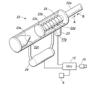
図6では、例えば3列シート構造の車両における最後尾のシート21に対して後突時用アクチュエータ22が設けられている。この後突時用アクチュエータ22にあっては、図7に併せて示されるように、上記と同様に車体フレームに固定された円筒状のシリンダ22b内に円板状ピストン22cが軸線方向に往復動自在に受容され、そのピストン22cに同軸的にピストンロッド22aが一体に形成されており、ピストンロッド22aの突出端部がシリンダ22bの外部に出て上記と同様にシート21に結合されている。
In FIG. 6, for example, a
なお、シート21は前後調節可能でなくても良いが、その場合にはシート21と車体フレームとが上記と同様に摩擦係合していると良い。また、シート21がシートレールによる前後調節可能な機構を有している場合には、上記と同様にその固定側レールにピストンロッド22aの突出端部が結合されていれば良い。
The
シリンダ22bの外部には、シリンダ22b内のピストン22cにより仕切られた一方の部屋(ピストンロッド22aの突出側)に開口する開口22dに連通するガス発生器23が取り付けられており、シリンダ22b内のピストン22cにより仕切られた他方の部屋であってピストン22cに対向する端面には、ピストン22cに対向する向きに突出した吸収体22eが設けられている。この吸収体22eは、ピストン22cが衝突した場合に圧壊してエネルギを吸収する材質からなる。
A
また、シリンダ22の外部には例えばコンプレッサあるいはエアタンクであって良い流体圧発生装置24が設けられている。シリンダ22bのピストン22cにより仕切られた各部屋にはそれぞれ開口22f・22gが設けられており、各開口22f・22gには流体圧発生装置24の別個に開閉制御可能な各ポートがそれぞれ接続されている。さらに、図示例のものにあっては、ピストン22cと、シリンダ22におけるピストンロッド22aの突出側の軸線方向内端面との間に、ピストンロッド22aに巻装されたコイルばねからなるリターンスプリング25が設けられている。
Further, a
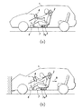
また、図6(a)に示されるように、後側バンパー内などの適所に車両後面衝突を予知するための衝突予知センサ10が設けられ、車体の適所に配置された衝突検出センサ6と制御ユニット12とが設けられている。制御ユニット12からの出力信号は後突時用アクチュエータ22のガス発生器23に入力されるようになっている。
Further, as shown in FIG. 6A, a
このようにして構成された乗員保護装置にあっては、後突が起きそうな場合(物体の相対的な後方からの接近)を衝突予知センサ10で検出したら、それに応じて制御ユニット12から流体圧発生装置24に衝突予知信号が出力される。その衝突予知信号に応じて流体圧発生装置24から開口22fへ高圧の圧縮流体が送出される。その圧縮流体がシリンダ22b内に入ると、ピストンロッド22aを外方(図7の矢印A)へ突出させる側へピストン22cが移動する。これにより、シート21が車両後方(第1段階方向)へ移動する(図6(b))。
In the occupant protection device configured as described above, when the
次に、衝突検出センサ6により衝突を検出したら、それに応じて制御ユニット12からガス発生器23にその推薬を爆発させる信号が出力される。それにより推薬が爆発して、爆発的に高圧となるガスが開口22dを介してシリンダ22b内の開口22d側の部屋へ噴出されるため、上記により第1段階方向へ移動したピストン22cが反対方向となる図7の矢印B方向へ移動する。これにより、シート21が図6(c)の矢印Bに示されるように車両前方(第2段階方向)へ移動する。
Next, when a collision is detected by the
このシート21の車両前方移動時には乗員の上体と頭部とがシートバック21aに押し付けられるため、乗員がシート21により拘束された状態になる。図6(c)に示されるように、乗員が一体となった状態のシート21が車両前方へ移動することにより、上記した前面衝突時の前席シート2の車両後方移動と同様の効果を奏し得る。
When the
上記第2段階方向への移動によりピストン22cが吸収体22eに衝当する。ピストン22cの衝当により吸収体22eが圧壊することにより、衝当によるエネルギを吸収してピストン22cすなわちシート21の車両前方移動に対するブレーキをかけることができる。
The
衝突予知センサ10は衝突予知を検出するものであり、その検出信号が出力されたら必ず衝突が起きるとは限らない。それゆえに、衝突が回避された場合には上記第1段階の方向への移動を可逆的なものとすると良い。そのように衝突が回避された場合には衝突検出センサ6から衝突検出信号が出力されないため、ガス発生器23の高圧ガス発生によりピストン22c(シート21)を車両前方へ移動させることにはならない。しかしながら、その場合にはピストン22cの車両後方移動によりリターンスプリング25が圧縮されており、その反発復元力によりピストン22cを元の位置に押し戻すことができる。それにより、衝突が回避された場合にまで本装置を交換する必要が無く、ランニングコストの低減及び省資源化に貢献し得る。
The
また、図示例のように流体圧発生装置24と連通する開口22gをシリンダ22bのピストン22cより車両後方側の部屋へ設けたものにあっては、その開口22gを介して圧縮流体を送り込むようにしても良い。あるいは、流体圧発生装置24により負圧を発生させて、衝突予知時にピストン22cを車両後方へ移動させるための圧縮流体をシリンダ22b内に送り込むための開口22fを利用して、シリンダ22b内のピストン22cより車両前方側の部屋の流体を吸い出すようにしても良い。この開口22fを利用する場合には開口の数を減らすことができ、部品コストを低減し得る。なお、これら流体圧を作用させるものにあっては、上記リターンスプリング25を設けないで行うことができるが、リターンスプリング25と合わせて行うようにしても良い。
Further, in the case where the
なお、ピストン22cすなわちシート21の前方移動終了時における乗員の速度及び加速度が車体の速度及び加速度と一致するように、シート21の反力の特性や吸収体22eのエネルギ吸収力の特性やピストン22cの移動距離が車種別に適宜設計されていると良い。
Note that the reaction force characteristics of the
1 車両
2 シート
6 衝突検出センサ
7 前席用アクチュエータ(シート移動装置)
10 衝突予知センサ
14 シートベルト巻き取り装置(シートベルト規制手段)
16 シートベルト
22 後突時用アクチュエータ(シート移動装置)
1
10
16
Claims (2)
前記シート移動装置により前記シートを、前記衝突予知センサによる衝突予知信号に応じて予知された車両衝突方向に予め移動させてから、前記衝突検出センサによる衝突検出信号に応じて前記予め移動させた方向とは逆向きに移動させるようにしたことを特徴とする乗員保護装置。 A collision prediction sensor for predicting at least one of the collisions in the longitudinal direction of the vehicle; a collision detection sensor for detecting that the vehicle has collided in the longitudinal direction; and a seat moving device for moving the seat in the longitudinal direction of the vehicle. ,
The direction in which the seat is moved in advance in the vehicle collision direction predicted according to the collision prediction signal from the collision prediction sensor and then moved in advance according to the collision detection signal from the collision detection sensor. An occupant protection device characterized by being moved in the opposite direction.
Priority Applications (1)
| Application Number | Priority Date | Filing Date | Title |
|---|---|---|---|
| JP2004132915A JP2005297931A (en) | 2004-03-19 | 2004-04-28 | Crew protection device |
Applications Claiming Priority (2)
| Application Number | Priority Date | Filing Date | Title |
|---|---|---|---|
| JP2004080355 | 2004-03-19 | ||
| JP2004132915A JP2005297931A (en) | 2004-03-19 | 2004-04-28 | Crew protection device |
Publications (1)
| Publication Number | Publication Date |
|---|---|
| JP2005297931A true JP2005297931A (en) | 2005-10-27 |
Family
ID=35329978
Family Applications (1)
| Application Number | Title | Priority Date | Filing Date |
|---|---|---|---|
| JP2004132915A Pending JP2005297931A (en) | 2004-03-19 | 2004-04-28 | Crew protection device |
Country Status (1)
| Country | Link |
|---|---|
| JP (1) | JP2005297931A (en) |
Cited By (6)
| Publication number | Priority date | Publication date | Assignee | Title |
|---|---|---|---|---|
| JP2006159979A (en) * | 2004-12-03 | 2006-06-22 | Mazda Motor Corp | Seat device for vehicle |
| WO2008052380A1 (en) * | 2006-09-29 | 2008-05-08 | Chien-Chung Feng | A vehicular reverse actuating system |
| WO2015041269A1 (en) * | 2013-09-18 | 2015-03-26 | 有限会社ジロウコレクション | Sliding seat structure for automobile, and automobile equipped with said structure |
| US11148562B2 (en) | 2018-09-27 | 2021-10-19 | Toyota Jidosha Kabushiki Kaisha | Vehicle seat structure |
| CN115709695A (en) * | 2022-11-16 | 2023-02-24 | 吉利汽车研究院(宁波)有限公司 | Vehicle collision safety protection method and system and vehicle |
| WO2025145821A1 (en) * | 2024-01-02 | 2025-07-10 | 金龙联合汽车工业(苏州)有限公司 | Danger-avoidance warning system for passenger car, and control method therefor |
-
2004
- 2004-04-28 JP JP2004132915A patent/JP2005297931A/en active Pending
Cited By (6)
| Publication number | Priority date | Publication date | Assignee | Title |
|---|---|---|---|---|
| JP2006159979A (en) * | 2004-12-03 | 2006-06-22 | Mazda Motor Corp | Seat device for vehicle |
| WO2008052380A1 (en) * | 2006-09-29 | 2008-05-08 | Chien-Chung Feng | A vehicular reverse actuating system |
| WO2015041269A1 (en) * | 2013-09-18 | 2015-03-26 | 有限会社ジロウコレクション | Sliding seat structure for automobile, and automobile equipped with said structure |
| US11148562B2 (en) | 2018-09-27 | 2021-10-19 | Toyota Jidosha Kabushiki Kaisha | Vehicle seat structure |
| CN115709695A (en) * | 2022-11-16 | 2023-02-24 | 吉利汽车研究院(宁波)有限公司 | Vehicle collision safety protection method and system and vehicle |
| WO2025145821A1 (en) * | 2024-01-02 | 2025-07-10 | 金龙联合汽车工业(苏州)有限公司 | Danger-avoidance warning system for passenger car, and control method therefor |
Similar Documents
| Publication | Publication Date | Title |
|---|---|---|
| US6193296B1 (en) | Vehicle occupant protection system | |
| US10486639B2 (en) | Occupant protection device | |
| JP5154229B2 (en) | Safety device | |
| US6463372B1 (en) | Vehicle collision damage reduction system | |
| US7441624B2 (en) | Passenger restraint device of motor vehicle | |
| US7206678B2 (en) | Motor vehicle with a pre-safe-system | |
| JP3904384B2 (en) | Crew protection device | |
| CN108454560B (en) | Variable force limiter control system for vehicle | |
| EP1378391A2 (en) | Vehicle occupant restraint system | |
| US9365139B2 (en) | Method and device for protecting and restraining a passenger and an evaluation and control unit for a protection and restraint device | |
| US6843504B2 (en) | Automotive vehicle occupant protection system | |
| US11745696B2 (en) | Adaptive dynamic lap belt position control system | |
| US6705645B2 (en) | Vehicle occupant protection system | |
| EP1266809B1 (en) | Automotive vehicle occupant protection system | |
| JP2023521547A (en) | A system that expands automotive parts to absorb impact in the event of an imminent collision | |
| EP4349660A1 (en) | Vehicle collision shock attenuation device | |
| JP2005297931A (en) | Crew protection device | |
| KR102856563B1 (en) | Airbag device and seat device placed in the backrest of a vehicle's movable seat device | |
| JP2006240351A (en) | Air bag device for vehicle | |
| JP7368127B2 (en) | Occupant protection device | |
| JP2006044409A (en) | Crew protection device | |
| JP4136876B2 (en) | Active knee bolster | |
| JP6577370B2 (en) | Vehicle front structure | |
| JP2005263076A (en) | Crew protection device | |
| KR102855725B1 (en) | Side air bag apparatus for vehicle |