JP2005297906A - Electric power steering device - Google Patents
Electric power steering device Download PDFInfo
- Publication number
- JP2005297906A JP2005297906A JP2004120407A JP2004120407A JP2005297906A JP 2005297906 A JP2005297906 A JP 2005297906A JP 2004120407 A JP2004120407 A JP 2004120407A JP 2004120407 A JP2004120407 A JP 2004120407A JP 2005297906 A JP2005297906 A JP 2005297906A
- Authority
- JP
- Japan
- Prior art keywords
- steering
- duty ratio
- switching
- motor
- electric power
- Prior art date
- Legal status (The legal status is an assumption and is not a legal conclusion. Google has not performed a legal analysis and makes no representation as to the accuracy of the status listed.)
- Pending
Links
Images
Classifications
-
- B—PERFORMING OPERATIONS; TRANSPORTING
- B62—LAND VEHICLES FOR TRAVELLING OTHERWISE THAN ON RAILS
- B62D—MOTOR VEHICLES; TRAILERS
- B62D5/00—Power-assisted or power-driven steering
- B62D5/04—Power-assisted or power-driven steering electrical, e.g. using an electric servo-motor connected to, or forming part of, the steering gear
- B62D5/0457—Power-assisted or power-driven steering electrical, e.g. using an electric servo-motor connected to, or forming part of, the steering gear characterised by control features of the drive means as such
- B62D5/046—Controlling the motor
Landscapes
- Engineering & Computer Science (AREA)
- Chemical & Material Sciences (AREA)
- Combustion & Propulsion (AREA)
- Transportation (AREA)
- Mechanical Engineering (AREA)
- Power Steering Mechanism (AREA)
- Steering Control In Accordance With Driving Conditions (AREA)
- Steering Controls (AREA)
Abstract
【課題】 スイッチング素子をスロースタートさせながら、低デューティ比でも不感帯の生じることがない電気式動力舵取装置を提供する。
【解決手段】 PWM制御のデューティ比が予め設定された値を越える際に(S14:No)、スイッチング周期を所定値(一定値)にする(S20)。デューティ比が予め設定された値以下になった時に(S14:Yes)、スイッチング周期を所定値より長くする(S16)。FETをスロースタートさせてノイズの発生を防ぎながら、低デューティ比でもスイッチング周期を長くすることで、確実にモータへ通電し、不感帯の発生を防げる。
【選択図】 図7
PROBLEM TO BE SOLVED: To provide an electric power steering apparatus in which a dead zone does not occur even at a low duty ratio while slow starting a switching element.
When a duty ratio of PWM control exceeds a preset value (S14: No), a switching cycle is set to a predetermined value (a constant value) (S20). When the duty ratio becomes equal to or less than a preset value (S14: Yes), the switching cycle is made longer than a predetermined value (S16). By preventing the generation of noise by slow-starting the FET, the motor can be reliably energized and the dead zone can be prevented by increasing the switching cycle even at a low duty ratio.
[Selection] Figure 7
Description
本発明は、モータにより操舵をアシストする電気式動力舵取装置に関し、特に、モータをPWM制御する電気式動力舵取装置に関するものである。 The present invention relates to an electric power steering apparatus that assists steering by a motor, and more particularly to an electric power steering apparatus that performs PWM control of a motor.
電気式動力舵取装置として、ステアリングホイールが固定された入力軸に、操舵トルクを検出するトルクセンサを取り付け、トルクセンサで検出した操舵トルクに応じたアシストトルクを電動モータにより発生させ操舵力を軽減するものが一般的に知られている。係る電気式動力舵取装置では、電動モータの印加電圧の調整を、一般的にPWM(パルス幅変調)制御でデューティ比を変えることで行っている。 As an electric power steering device, a torque sensor that detects steering torque is attached to the input shaft to which the steering wheel is fixed, and assist torque corresponding to the steering torque detected by the torque sensor is generated by the electric motor to reduce the steering force. It is generally known what to do. In such an electric power steering apparatus, adjustment of the applied voltage of the electric motor is generally performed by changing the duty ratio by PWM (pulse width modulation) control.
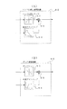
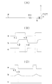
図11(A)は、スイッチングによりモータへの印加電圧の調整を行うFET回路を示している。FETのゲート側には、FETをスロースイッチングさせるための抵抗R1が接続され、スロースイッチングさせることで、矩形波状のパルスが生成されることによるノイズの発生を防いでいる。 FIG. 11A shows an FET circuit that adjusts the voltage applied to the motor by switching. A resistor R1 for slow switching the FET is connected to the gate side of the FET, and the slow switching prevents the generation of noise due to the generation of a rectangular wave pulse.
図11(B)中でaはFET回路の制御信号、bはFETのゲートへの印加電圧、cはFETのオンオフを示している。FET回路の制御信号aがハイレベルに切り替わってから(タイミングt1)、時定数回路による遅延があってFETのゲートへの印加電圧bがハイレベルに達し(タイミングt2)、これに伴いFETがオンする。同様に、FET回路の制御信号aがロウレベルに切り替わってから(タイミングt3)、時定数回路による遅延があってFETのゲートへの印加電圧bがロウレベルに達し(タイミングt4)、これに伴いFETがオフする。
ここで、特許文献1には、低デューティ比での不感帯を無くすため、低デューティ比時に電圧ディザ信号をモータへ印加する技術が開示されている。
Here,
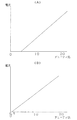
しかしながら、図11(A)に示すスロースイッチングFET回路では、低デューティ比時には、FETがオン出来ないという課題が発生する。即ち、図11(C)に示すよう低デューティ比時には、FET回路の制御信号aがハイレベルに切り替わってから(タイミングt1)、時定数回路による遅延があってFETのゲートへの印加電圧bがハイレベルに達する前に、FET回路の制御信号aがロウレベルに切り替わって(タイミングt3)、FETがオンできなくなる。図12(A)は、従来技術でのデューティ比と電流との関係を示すグラフである。デューティ比が零近辺では、電流が流れない状態、即ち、不感帯が発生している。係る不感帯を無くす方法としては、低デューティ比時にデューティ比の嵩上げを行うこともできるが、この方法では、FETのバラツキにより動作がばらつくため、FETのバラツキを無くす素子毎の単体調整(素子毎のマップ作成)を行わない限り、不感帯を完全に無くすことはできない。 However, the slow switching FET circuit shown in FIG. 11A has a problem that the FET cannot be turned on at a low duty ratio. That is, when the duty ratio is low as shown in FIG. 11C, after the control signal a of the FET circuit is switched to the high level (timing t1), there is a delay due to the time constant circuit, and the applied voltage b to the gate of the FET is Before reaching the high level, the control signal a of the FET circuit is switched to the low level (timing t3), and the FET cannot be turned on. FIG. 12A is a graph showing the relationship between the duty ratio and current in the prior art. When the duty ratio is near zero, no current flows, that is, a dead zone occurs. As a method for eliminating such dead zones, it is possible to increase the duty ratio at a low duty ratio. However, in this method, since the operation varies due to variations in FETs, individual adjustment for each element that eliminates variations in FETs (for each element) The dead zone cannot be completely eliminated unless (map creation) is performed.
特許文献1では、低デューティ比時には電圧ディザ信号をモータへ印加することで、低デューティ比での不感帯を無くしている。しかし、係る構成では、図11(A)に示すようなスロースイッチングを行うFET回路に適用することができず、ノイズの発生を防ぐことができなかった。
In
本発明は、上述した課題を解決するためになされたものであり、その目的とするところは、スイッチング素子をスロースタートさせながら、低デューティ比でも不感帯の生じることがない電気式動力舵取装置を提供することにある。
The present invention has been made to solve the above-described problems, and an object of the present invention is to provide an electric power steering apparatus that does not cause a dead band even at a low duty ratio while slow-starting a switching element. It is to provide.
請求項1の発明は、上記目的を達成するため、操舵状態を検出して操舵状態に応じた操舵補助指令値を演算する演算部と、操舵補助力を発生するモータと、スイッチング素子をスロースタートさせて前記モータへの通電を制御する通電制御回路と、演算された操舵補助指令値に基づき前記通電制御回路を介して前記モータをPWM制御するモータ制御部とを備える電気式動力舵取装置において、
前記PWM制御のデューティ比が予め設定された値を越える際に、スイッチング周期を所定値(一定値)にし、デューティ比が前記予め設定された値以下になった時に、前記スイッチング周期を前記所定値より長くするスイッチング周期調整手段を備えることを技術的特徴とする。
In order to achieve the above object, the invention according to
When the duty ratio of the PWM control exceeds a preset value, the switching period is set to a predetermined value (a constant value), and when the duty ratio becomes equal to or less than the preset value, the switching period is set to the predetermined value. It is a technical feature that a switching period adjusting means for increasing the length is provided.
請求項1の電気式動力舵取装置では、PWM制御のデューティ比が予め設定された値を越える際に、スイッチング周期を所定値(一定値)にし、デューティ比が予め設定された値以下になった時に、スイッチング周期を前記所定値より長くする。このため、スイッチング素子をスロースタートさせてノイズの発生を防ぎながら、低デューティ比でもスイッチング周期を長くすることで、確実にモータへ通電し、不感帯の生じることを防ぐことができる。これにより、操舵時の応答遅れを改善し、操舵感を向上させることが可能である。 In the electric power steering apparatus according to the first aspect, when the duty ratio of the PWM control exceeds a preset value, the switching cycle is set to a predetermined value (constant value), and the duty ratio becomes equal to or less than the preset value. The switching period is made longer than the predetermined value. For this reason, it is possible to prevent the dead zone from being generated by energizing the motor reliably by lengthening the switching cycle even at a low duty ratio while preventing the generation of noise by slow starting the switching element. Thereby, it is possible to improve response delay during steering and improve steering feeling.
請求項2の電気式動力舵取装置では、スイッチング周期を長くするかを判断するための予め設定された値が、一定のスイッチング周期では、スイッチング素子をオンできなくなるデューティ比である。このため、一定のスイッチング周期ではスイッチング素子をオンできなくなるデューティ比において、スイッチング周期を長くすることで、確実にモータへ通電し、不感帯の生じることを防ぐことができる。 In the electric power steering apparatus according to the second aspect, a preset value for determining whether or not to increase the switching period is a duty ratio at which the switching element cannot be turned on at a constant switching period. For this reason, it is possible to prevent the dead zone from being generated by reliably energizing the motor by increasing the switching period at a duty ratio at which the switching element cannot be turned on at a constant switching period.
請求項3の電気式動力舵取装置では、長くするスイッチング周期(Tn)は、スイッチング素子のスロースタート時間をTd、当該スイッチングのバラツキを無くすための余裕時間をPm、デューティ比(%)をDnとした際に、Tn=(Td+Pm)×100/Dnで表される。スロースタート時間Tdに加えて、当該スイッチングのバラツキを無くすための余裕時間Pmを考慮してスイッチング周期を決定するため、スイッチング素子及びスイッチング素子に接続される素子のバラツキがあっても、スイッチング素子を確実にスロースタートさせることができる。
In the electric power steering apparatus according to
請求項4の電気式動力舵取装置は、ステアリングホイールと操舵輪とを連結する操舵伝達系の途中に電動モータの駆動により伝達比を可変する伝達比可変手段を備える。このため、電流フィードバックを行うことなく、ギヤ比可変システムでオープンループで制御を行っても、操舵時の応答遅れを無くすことができる。 According to a fourth aspect of the present invention, there is provided an electric power steering apparatus including transmission ratio variable means for varying a transmission ratio by driving an electric motor in the middle of a steering transmission system that couples a steering wheel and a steering wheel. For this reason, even if control is performed in an open loop with a gear ratio variable system without performing current feedback, a response delay during steering can be eliminated.
以下、本発明の実施形態に係る電気式動力舵取装置について図を参照して説明する。
[第1実施形態]
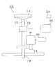
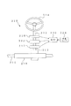
図1は第1実施態様の電気式動力舵取装置10の構成を示すブロック図である。電気式動力舵取装置10は、操舵トルクを検出するためのトルクセンサ22と、トルクセンサ22からの操舵トルク及び車速センサ24からの車速に基づきモータ指令トルク(操舵アシスト量)を演算する制御装置30と、モータ指令トルクに応じた電流指令値を求めてモータMへの通電を制御するモータ駆動回路26とを備える。
Hereinafter, an electric power steering apparatus according to an embodiment of the present invention will be described with reference to the drawings.
[First embodiment]
FIG. 1 is a block diagram showing a configuration of an electric
トルクセンサ22は、車両の操舵ステアリング14に連結された入力軸12に配設されている。モータMの出力は、減速機16により減速され、前輪を操舵するためのラック・ピニオンギア18に伝達される。
The
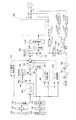
制御装置30及びモータ駆動回路26の制御系について、図2のブロック図に示す。トルクセンサ22からの出力(操舵トルク:電圧値)は、A/D変換32を介してデジタル値に変換され、トルク演算34にてトルク値が演算される。演算されたトルク値は、ローパスフィルタ36にてノイズが除去され、加算ノード38を介してアシスト制御60へ入力される。一方、車速センサ24からの車速(パルス信号)は、I/F40を介して車速演算42に入力され、演算された車速がアシスト制御60へ入力される。一方、ローパスフィルタ36からの出力は、微分44を介して、位相補償46にて位相補償され、加算ノード38を介してアシスト制御60へ入力される。該位相補償46は、操舵トルク値を微分44にて微分することで位相を進め、操舵アシストの遅れを補償する。即ち、検出値に基づき指令値を演算すると、演算完了までに一定の時間がかかり、この一定時間が、検出値に対する指令値の遅れとなって、現在の検出値に基づいて指令値を求めると、操舵アシストを適正に制御し得ない。このため、該位相補償46が操舵トルクの位相を進める。
The control system of the
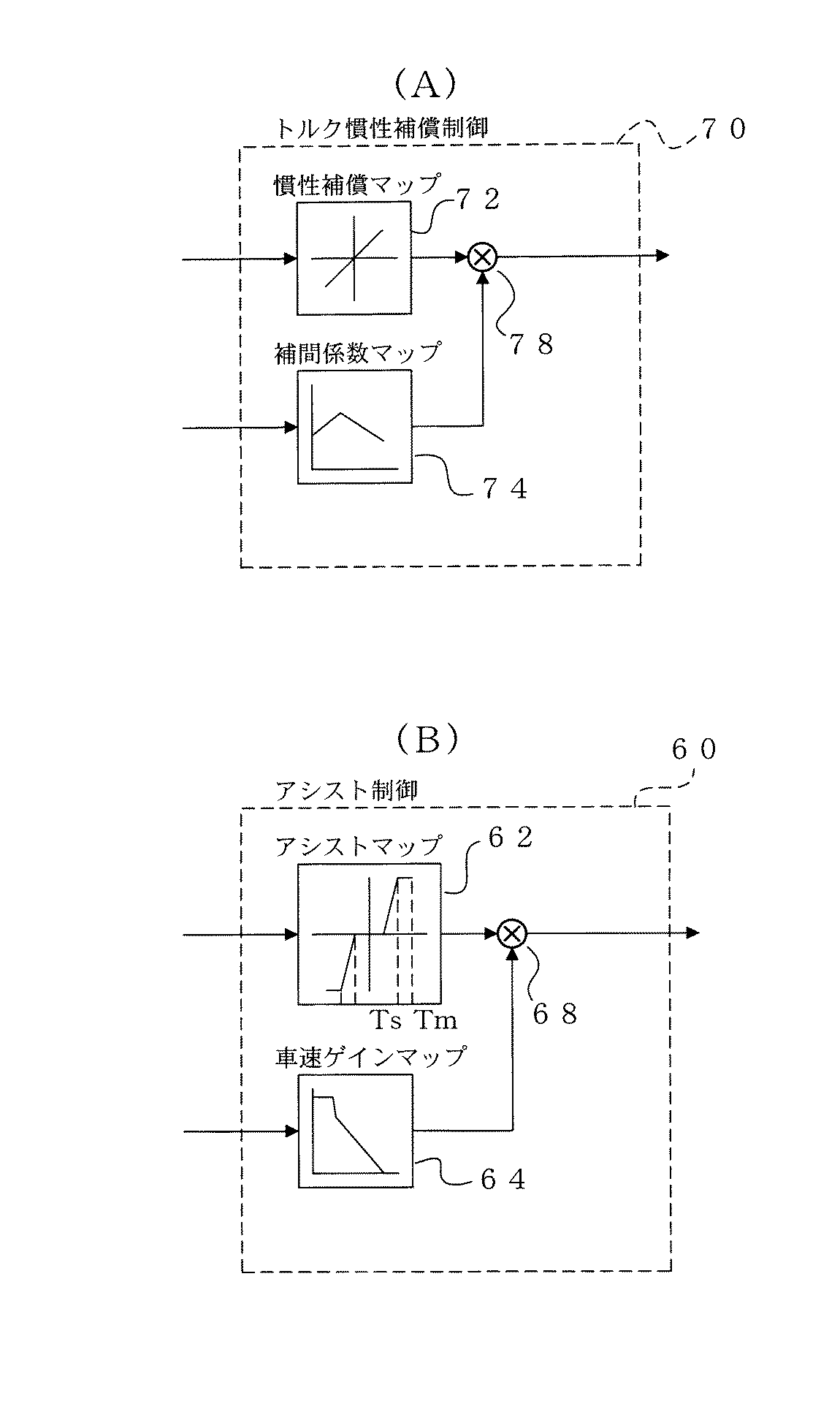
アシスト制御60の内容を図4(B)に示す。加算ノード38からの操舵トルクに応じて、アシストマップ62により、指令トルク値が決定される。即ち、操舵トルクが大きいときには、高い指令トルク値が決定され、操舵トルクが小さいときには、低い指令トルク値が決定され、乗算ノード68側へ出力される。また、第1実施形態の電気式動力舵取装置においては、操舵トルクが所定値よりも小さいときには、該操舵トルクに応じたモータ制御を行わないようにする「不感帯」を設けてある。即ち、不感帯を設けることで、中、高速走行時のステアリング中立付近での剛性感を高め、操舵フィーリングを高めている。すなわち、操舵トルクの絶対値がTsよりも小さなときは、指令トルクが0として出力される。また、所定の操舵トルクTmよりも大きいときには、最大値として一定の指令トルク値(モータの最大出力)が出力される。
The contents of the
車速センサ24からの車速値は、車速ゲインマップ64により車速に応じた重み付けが行われる。車速に応じて車速ゲインマップを検索することで、例えば、車速0km/hの際には“1”を出力し、100km/hの際には“0.2”を出力する。これにより、操舵アシスト量を車速に応じて重み付けを行うことでステアリングを操作する際、低速時に操舵を軽く、反対に、高速時に操舵を重くしている。車速ゲインマップ64からの車速重み付け値が乗算ノード68側へ出力され、上述した指令トルクが車速に応じて補正される。
The vehicle speed value from the
図2に示すように、アシスト制御60からの指令トルク値は、加算ノード48を介して電流指令リミッタ50に加えられる。電流指令リミッタ50では、モータMの最大出力を越える指令トルク値が制限される。
As shown in FIG. 2, the command torque value from the
電流指令リミッタ50からの指令トルク値は、減算ノード52を介してPI制御100に加えられる。PI制御100の内容を図6に示す。PI制御100では、指令トルク値にGpゲインが乗算され、加算ノード102に印加され、また、指令トルク値が微分されGiゲインが乗算され、加算ノード102へ印加される。一方、上記減算ノード52へは、ローパスフィルタ112及びA/D変換114を介してモータMの電流が印加される。PI制御100では、A/D変換114を介して入力された実モータ電流が、指令トルク値(指令電流値)となるようにPIフィードバック制御が行われる。
The command torque value from the
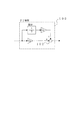
PI制御100からの指令トルク値は、周期制御110を介してモータ駆動回路26へ印加される。図3は、モータ駆動回路26の回路構成を示している。モータ駆動回路26は、4個のFET1、FET2、FET3、FET4のブリッジと、FET1、FET2、FET3、FET4のゲートに電圧を印加し、周期制御110で規定されたスイッチング周期で、指令トルク値に応じた出力をモータMに発生させるPWM制御を行うPWM演算27とを備える。各FET1、FET2、FET3、FET4のゲート側には、図11(A)を参照して上述した従来技術と同様に、スロースイッチングさせるための抵抗R1が接続され、スロースイッチングさせることで、ノイズの発生を防いでいる。
The command torque value from the PI control 100 is applied to the
モータU相の電位は、ローパスフィルタ122及びA/D変換124を介して差動アンプ136の非反転入力に加えられる。モータV相の電位は、ローパスフィルタ132及びA/D変換134を介して差動アンプ136の反転入力に加えられる。差動アンプ136からモータ端子間電圧が出力され、減算ノード54へ印加される。上述したA/D変換114を介して入力されたモータ電流が、(LS+R)138で乗算されてモータ起電力として減算ノード54へ印加され、減算ノード54からモータの逆起電力が出力される。ここで、乗算される(LS+R)中のLSは、モータインダクタンスの微分値を、Rは、モータの抵抗分を示している。
The motor U-phase potential is applied to the non-inverting input of the
減算ノード54からの逆起電力は、アンプ56にて逆起電力定数Keが除算され、モータの角速度が求められ、更に、アンプ58にて減速機16の減速比Giが除算されて、ハンドルの角速度ωとして、ハンドル戻し補償制御80及びダンパ補償制御90へ印加される。ここでは、ハンドルの角速度ωを演算により推測しているが、舵角センサにより角速度を検出することも可能である。
The counter electromotive force from the
ハンドル戻し補償制御80は、低速において路面の反力による舵の戻りがモータMと減速機16の摩擦抵抗により遅くなる電気式動力舵取装置の特性を補償するための制御を行う。ハンドル戻し補償制御80の内容を図5(A)に示す。ハンドルの角速度に応じて、ハンドル戻しマップ82により、ハンドル戻し量が決定される。即ち、ハンドルの角速度が大きいときには、大きなハンドルの戻り量が決定され、角速度が小さいときには、小さなハンドルの戻り量が決定され、乗算ノード88側へ出力される。第1実施形態の電気式動力舵取装置のハンドル戻しマップ82においては、上述したアシストマップ62と同様に、角速度が所定値よりも小さいときには、角速度に応じたモータ制御を行わないようにする「不感帯」を設けてある。また、また、所定の角速度よりも大きいときには、最大値として一定のハンドルの戻り量が出力される。
The steering wheel
車速センサ24からの車速値は、車速ゲインマップ84により車速に応じた重み付けが行われる。車速に応じて車速ゲインマップを検索することで、例えば、車速0km/hの際には“1”を出力し、40km/hの際には“0.2”を出力する。これにより、低速においてハンドル戻し量を大きくし、中高速では戻り量を小さくしている。車速ゲインマップ84からの車速重み付け値が乗算ノード88側へ出力され、上述したハンドルの戻り量が車速に応じて補正される。ハンドル戻し補償制御80の出力は、加算ノード48へ印加される。
なお、ハンドル戻し補償制御80は、ハンドルの角速度に代えて、モータMの角速度に応じてハンドル戻し量を決定するようにしてもよい。
The vehicle speed value from the
Note that the steering wheel
一方、図2に示すダンパ補償制御90は、中高速で路面の反力による舵の戻りが早くなるのを補償する。これは一旦舵が戻り始めると、モータMと減速機16の慣性により舵が戻りすぎるのを防止するためである。ダンパ補償制御90の内容を図5(B)に示す。ハンドルの角速度に応じて、ダンパマップ92により、ダンパ量が決定される。即ち、ハンドルの角速度が大きいときには、ハンドルの回転方向とは逆方向への大きなダンパ量(小さなハンドル戻り量)が決定され、角速度が小さいときには、小さなダンパ量(大きなハンドル戻り量)が決定され、乗算ノード98側へ出力される。ダンパマップ92は、上述したアシストマップ62と同様に、角速度が所定値よりも小さいときには、角速度に応じたモータ制御を行わないようにする「不感帯」を設けてある。また、また、所定の角速度よりも大きいときには、最大値として一定のダンパ量が出力される。
On the other hand, the
車速センサ24からの車速値は、車速ゲインマップ94により車速に応じた重み付けが行われる。車速に応じて車速ゲインマップを検索することで、例えば、車速0km/hの際には“0”を出力し、40km/hの際には“0.6”を出力する。これにより、高速においてダンパ量を大きくし、低速ではダンパ量を小さくしている。車速ゲインマップ94からの車速重み付け値が乗算ノード98側へ出力され、上述したダンパ量が車速に応じて補正される。車速により補正されたダンパ量が、図2に示す加算ノード48へ印加され、アシスト制御60からの指令トルク値を補償する。
なお、ダンパ補償制御90はハンドルの角速度に代えて、モータMの角速度に応じてダンパ量を決定するようにしてもよい。
The vehicle speed value from the
The
図2に示すように、操舵トルクの微分値、車速値は、トルク慣性補償制御70に入力される。トルク慣性補償制御70は、切り始めに舵が重く、一旦切り始めると、舵がどんどん切れて行く慣性感を軽減する。トルク慣性補償制御70の内容を図4(A)に示す。微分44で微分された操舵トルクに応じて、慣性補償マップ72により慣性補償量が決定される。即ち、操舵トルク微分値が大きいときには、高い慣性補償量が決定され、操舵トルクが小さいときには、低い慣性補償量が決定され、乗算ノード78側へ出力される。
As shown in FIG. 2, the steering torque differential value and the vehicle speed value are input to the torque inertia compensation control 70. The torque inertia compensation control 70 reduces the feeling of inertia that the rudder is severed at the start of turning and once the rudder is turned off. The contents of the torque inertia compensation control 70 are shown in FIG. The inertia compensation amount is determined by the inertia compensation map 72 according to the steering torque differentiated by the
車速センサ24からの車速値は、補間係数マップ74により車速に対応する重み付けが行われる。例えば、車速0km/hの際には“0.7”を出力し、40km/hの際には“1.0”を出力し、70km/hの際には“0.6”を出力する。これにより、慣性補償量を低速で小さく、中速で大きく、高速で小さくしている。補間係数マップ74からの重み付け値が乗算ノード78側へ出力され、上述した慣性補償量が車速に応じて補正される。車速により補正された慣性補償量が、図2に示す加算ノード48へ印加され、アシスト制御60からの指令トルク値を補償する。
The vehicle speed value from the
ここで、周期制御110によるPWM制御のスイッチング周期の切り替えについて図7及び図8を参照して説明する。
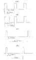
図8(A)、図8(B)は、高デューティ比時の一定周期でのスイッチングを示すタイミングチャートであり、図8(C)、図8(D)は、低デューティ比時の周期を長くした際のスイッチングを示すタイミングチャートである。
Here, switching of the switching cycle of the PWM control by the
FIGS. 8A and 8B are timing charts showing switching at a constant cycle when the duty ratio is high. FIGS. 8C and 8D show the cycle when the duty ratio is low. It is a timing chart which shows switching at the time of lengthening.
第1実施形態では、デューティ比が16%が越えている際には、FETのスイッチング周波数(PWM制御のスイッチング周波数)を20KHz(スイッチング周期0.5ms)で一定にし、デューティ比に応じてFETのオン時間を調整する。図8(A)は、デューティ比20%の際のスイッチングを示している。ここでは、0.5ms周期で、0.1ms間FETをオンする(実際には、遅延回路分遅れてターンオン、ターンオフする)。また、図8(B)は、デューティ比40%の際のスイッチングを示している。ここでは、0.5ms周期で、0.2ms間FETをオンする。 In the first embodiment, when the duty ratio exceeds 16%, the FET switching frequency (PWM control switching frequency) is kept constant at 20 KHz (switching period 0.5 ms), and the FET switching frequency is set according to the duty ratio. Adjust the on-time. FIG. 8A shows switching when the duty ratio is 20%. Here, the FET is turned on for 0.1 ms with a period of 0.5 ms (actually, the FET is turned on and turned off with a delay of the delay circuit). FIG. 8B shows switching when the duty ratio is 40%. Here, the FET is turned on for 0.2 ms with a period of 0.5 ms.
一方、デューティ比が16%以下の低デューティ比の際には、FETのスイッチング周波数(PWM制御のスイッチング周波数)を可変にし、オン時間を一定にしてデューティ比に応じてスイッチング周期を調整する。図8(C)は、デューティ比3%の際のスイッチングを示している。ここでは、2.67ms周期で、0.08ms間FETをオンする。また、図8(D)は、デューティ比4%の際のスイッチングを示している。ここでは、2ms周期で、0.08ms間FETをオンする。 On the other hand, when the duty ratio is a low duty ratio of 16% or less, the switching frequency of the FET (the switching frequency of PWM control) is made variable, the ON time is made constant, and the switching cycle is adjusted according to the duty ratio. FIG. 8C shows switching when the duty ratio is 3%. Here, the FET is turned on for 0.08 ms in a cycle of 2.67 ms. FIG. 8D shows switching when the duty ratio is 4%. Here, the FET is turned on for 0.08 ms in a cycle of 2 ms.
図3を参照して上述したFETのゲート側に接続された抵抗R1からなる時定数回路による遅延時間は、即ち、ノイズを防ぐために必要とされる遅延時間(スイッチ遅れ時間Td)は0.03ms程度である。一方、抵抗R1、FET等の素子のバラツキ、素子特性の温度変化等を考慮すると、FETを確実にオンさせるようにするマージン(余裕)時間は0.05ms程度である。このため、第1実施形態では、FETのオン時間、即ち、図3中に示すPWM演算27からのU相、V相、インバータU相、インバータV相のオン時間は、0.08ms(0.03ms+0.05ms)に設定されており、図8(C)、図8(D)を参照して上述したようにスイッチング周期側を可変にする。これにより、FET1、FET2、FET3、FET4を確実にオンさせる。
The delay time by the time constant circuit composed of the resistor R1 connected to the gate side of the FET described above with reference to FIG. 3, that is, the delay time (switch delay time Td) required to prevent noise is 0.03 ms. Degree. On the other hand, in consideration of variations in the elements such as the resistor R1 and the FET, temperature changes in the element characteristics, etc., the margin time required to reliably turn on the FET is about 0.05 ms. For this reason, in the first embodiment, the ON time of the FET, that is, the ON time of the U phase, V phase, inverter U phase, and inverter V phase from the
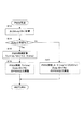
周期制御110によるPWM制御のスイッチング周期決定の処理について図7のフローチャートを参照して説明する。
まず、出力デューティ比(Dn)を計算する(S12)。ここで、小数点以下は四捨五入して%単位で計算し、0.4%は、0%に、0.5%は1%とする。次に、デューティ比が所定値(例えば16%)以下かを判断する(S14)。ここで、デューティ比が所定値を越える場合には(S14:No)、PWM周期を0.5ms、即ち、PWM周波数を20KHzに一定とし、デューティ比に応じたオン時間、例えば、図8(A)を参照して上述したようにデューティ比20%の際にはオン時間0.1msを、図8(B)を参照して上述したようにデューティ比40%の際にはオン時間0.2msを設定する。
Processing for determining the switching cycle of PWM control by
First, an output duty ratio (Dn) is calculated (S12). Here, the figures after the decimal point are rounded off and calculated in% units. 0.4% is 0% and 0.5% is 1%. Next, it is determined whether the duty ratio is a predetermined value (for example, 16%) or less (S14). Here, when the duty ratio exceeds a predetermined value (S14: No), the PWM period is set to 0.5 ms, that is, the PWM frequency is fixed to 20 KHz, and the ON time according to the duty ratio, for example, FIG. ), The on-time is 0.1 ms when the duty ratio is 20%, and the on-time is 0.2 ms when the duty ratio is 40% as described above with reference to FIG. Set.
一方、次に、デューティ比が所定値(16%)以下の場合には(S14:Yes)、先ず、PWM制御のスイッチング周期Tnを計算する(S16)。ここで、切替デューティをZ、デューティ比をDn、20KHz時の周期(0.5ms)としたとき、スイッチング周期Tnは次式で求められる。
ここで、切替デューティZは、上述したスイッチ遅れ時間をTdとし、マージン(余裕)時間をPmとしたとき次式で求められる。
即ち、スイッチング周期Tnは次式で求めることができる。
![]()
![]()
例えば、上述したようにスイッチ遅れ時間Tdに0.03ms、マージン(余裕)時間Pmに0.05msを用いると、デューティ比1%でスイッチング周期Tnが8ms、デューティ比2%でスイッチング周期Tnが4ms、デューティ比3%でスイッチング周期Tnが2.67ms、デューティ比4%でスイッチング周期Tnが2ms、デューティ比5%でスイッチング周期Tnが1.6ms、デューティ比6%でスイッチング周期Tnが1.3msとなる。 For example, as described above, when 0.03 ms is used for the switch delay time Td and 0.05 ms is used for the margin time Pm, the switching cycle Tn is 8 ms with a duty ratio of 1%, and the switching cycle Tn is 4 ms with a duty ratio of 2%. When the duty ratio is 3%, the switching period Tn is 2.67 ms, when the duty ratio is 4%, the switching period Tn is 2 ms, when the duty ratio is 5%, the switching period Tn is 1.6 ms, and when the duty ratio is 6%, the switching period Tn is 1.3 ms. It becomes.
そして、算出したPWM周期Tnで、上述したようにデューティ比に対応するようにPWM出力を実行し(S18)、処理を終了する。 Then, in the calculated PWM cycle Tn, PWM output is executed so as to correspond to the duty ratio as described above (S18), and the process is terminated.
第1実施形態では、スロースタート時間Tdに加えて、当該スイッチングのバラツキを無くすための余裕時間Pmを考慮してスイッチング周期を決定するため、FET等のスイッチング素子及びスイッチング素子に接続される素子のバラツキがあっても、スイッチング素子を確実にスロースタートさせることができる。 In the first embodiment, in addition to the slow start time Td, the switching period is determined in consideration of the margin time Pm for eliminating the switching variation. Therefore, the switching elements such as FETs and the elements connected to the switching elements are determined. Even if there is a variation, the switching element can be surely started slowly.
ここで、図7中のステップS14で、スイッチング周期を長くするかを判断するための所定値(上述した例では16%)は、一定のスイッチング周期では、スイッチング素子をオンできなくなるデューティ比が設定されている。即ち、スイッチング周期(0.5ms:PWM周波数20KHz)では、16%の時に、オン周期が0.5×0.16=0.08(ms)となり、上述したスイッチ遅れ時間Td(0.03ms)、マージン(余裕)時間Pm(0.05ms)を加えた時間と等しくなり、これよりも短いと確実にFETをオンすることができなくなる。このため、一定のスイッチング周期ではスイッチング素子をオンできなくなるデューティ比以下において、スイッチング周期を長くすることで、確実にモータへ通電し、不感帯の生じることを防ぐことができる。
Here, in step S14 in FIG. 7, a predetermined value (16% in the above example) for determining whether or not to increase the switching cycle is set to a duty ratio at which the switching element cannot be turned on in a certain switching cycle. Has been. That is, in the switching cycle (0.5 ms:
なお、上述したようにデューティ比は、%単位で四捨五入した。これは、例えば、デューティ比0.1%の際に通電を行うと、スイッチング周期Tnが80msとなって、係る間欠的な周期でモータを制御するとステアリングに振動を生じさせることになるので、これを防ぐためである。 As described above, the duty ratio is rounded to the nearest unit. This is because, for example, when energization is performed at a duty ratio of 0.1%, the switching period Tn becomes 80 ms, and if the motor is controlled at such an intermittent period, vibrations are generated in the steering wheel. Is to prevent.
図12(B)は、第1実施形態でのデューティ比とモータ電流との関係を示すグラフである。デューティ比が0〜0.4%までは、電流が流れない状態、即ち、不感帯が発生しているが、0.5%を越えるとデューティ比に応じてモータに電流を流すことができる。即ち、不感帯は、0.4%以下であり、事実上不感帯を無くすことができる。 FIG. 12B is a graph showing the relationship between the duty ratio and the motor current in the first embodiment. When the duty ratio is 0 to 0.4%, no current flows, that is, a dead zone occurs. However, when the duty ratio exceeds 0.5%, the current can be supplied to the motor according to the duty ratio. That is, the dead zone is 0.4% or less, and the dead zone can be virtually eliminated.
第1実施形態では、PWM制御のデューティ比が予め設定された値を越える際に、スイッチング周期を一定にし、デューティ比が予め設定された値以下になった時に、スイッチング周期を長くする。このため、FET、トランジスタ等のスイッチング素子をスロースタートさせてノイズの発生を防ぎながら、低デューティ比でもスイッチング周期を長くすることで、確実にモータへ通電し、不感帯の生じることを防ぐことができる。これにより、操舵時の応答遅れを改善し、操舵感を向上させることが可能である。 In the first embodiment, when the duty ratio of PWM control exceeds a preset value, the switching period is made constant, and when the duty ratio becomes equal to or less than a preset value, the switching period is lengthened. For this reason, it is possible to prevent the occurrence of dead zones by reliably energizing the motor by slowing the switching elements such as FETs and transistors to prevent the generation of noise and by increasing the switching period even at a low duty ratio. . Thereby, it is possible to improve response delay during steering and improve steering feeling.
[第2実施形態]
上述した第1実施形態では、本発明の構成を電気式動力舵取装置のアシストトルク調整に用いた。これに対して、第2実施形態では、ステアリングホイールと操舵輪とを連結する操舵伝達系の途中に電動モータの駆動により伝達比を可変する伝達比可変手段を備えた電気式動力舵取装置に関するものである。
[Second Embodiment]
In 1st Embodiment mentioned above, the structure of this invention was used for the assist torque adjustment of an electric power steering device. On the other hand, the second embodiment relates to an electric power steering apparatus provided with a transmission ratio variable means for varying a transmission ratio by driving an electric motor in the middle of a steering transmission system that connects a steering wheel and a steering wheel. Is.
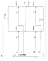
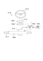
図9に示すように、電気式動力舵取装置210は、主に、ステアリングホイール214、第1ステアリングシャフト212、第2ステアリングシャフト213、ステアリングギヤボックス218、操舵角センサ216、車速センサ224、出力角センサ217、ECU230、ギヤ比可変ユニット222から構成されている。
As shown in FIG. 9, the electric
即ち、ステアリングホイール214に第1ステアリングシャフト212の一端が接続され、この第1ステアリングシャフト212の他端側にはギヤ比可変ユニット222の入力側が接続される。このギヤ比可変ユニット222はモータ、減速機等から構成されており、この出力側には第2ステアリングシャフト213の一端側が接続され、第2ステアリングシャフト213の他端側にはステアリングギヤボックス218の入力側が接続される。そして、ステアリングギヤボックス218は図示しないラック・ピニオンギヤ等により、第2ステアリングシャフト213によって入力された回転運動をロッド215の軸方向運動に変換して出力し得るように構成される。また、第1ステアリングシャフト212の回転角(操舵角)は操舵角センサ216により、第2ステアリングシャフト213の回転角(出力角)は出力角センサ217により、車両速度は車速センサ224により、それぞれ検出され、操舵角信号、出力角信号、車速信号としてECU230にそれぞれ入力され得るように構成される。
That is, one end of the
このように構成することによって、ギヤ比可変ユニット222では、モータと減速機により、入力ギヤに対する出力ギヤの比を車速に応じてリアルタイムに変更し、第1ステアリングシャフト212の操舵角に対する第2ステアリングシャフト213の出力角の比を可変する。つまり、操舵角センサ216による操舵角信号と車速センサ224による車速信号とをECU230に入力することにより、車速に対応して一義的に定められるギヤ比可変ユニット222のモータの回転角をモータ回転角マップから決定し、決定した回転角指令値に応じたモータ電圧を増幅回路(図示せず)を介してモータ駆動回路(図示せず)に供給する。
With this configuration, in the gear
これにより、車速に対応したステアリングギヤ比、例えば停車時や低速走行時にはステアリングホイールの操舵角に対してギヤ比可変ユニット222の出力角が大きくなるように設定し、また高速走行時にはステアリングホイールの操舵角に対してギヤ比可変ユニット222の出力角が小さくなるように設定することができる。つまり、ギヤ比可変ユニット222は、ステアリングホイールの取り回しを改善することを主目的に構成されている。
As a result, the steering gear ratio corresponding to the vehicle speed is set so that the output angle of the gear
このECU230は、第1実施形態と同様にギヤ比可変ユニット222のモータを、低デューティ比の際にはスイッチング周期を可変にしてPWM制御してる。
Similar to the first embodiment, the
この第2実施形態では、モータの電流センサを無くし、電流フィードバックを行うことなくオープンループで制御を行っても、操舵時の応答遅れを無くすことができる。 In the second embodiment, even if the current sensor of the motor is eliminated and control is performed in an open loop without performing current feedback, a response delay during steering can be eliminated.
[第3実施形態]
上述した第1実施形態では、本発明の構成を電気式動力舵取装置のアシストトルク調整に用いた。これに対して、第3実施形態では、ステアリングホイールの操作を検出し、制御装置によってアクチュエータを駆動して操舵を行うSBW(ステアバイワイヤ)式の電気式動力舵取装置に関するものである。
[Third embodiment]
In 1st Embodiment mentioned above, the structure of this invention was used for the assist torque adjustment of an electric power steering device. On the other hand, the third embodiment relates to an SBW (steer-by-wire) type electric power steering apparatus that detects an operation of a steering wheel and drives an actuator by a control device to perform steering.
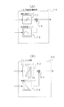
図10に示すように、電気式動力舵取装置310は、主に、ステアリングホイール314、ステアリングシャフト312、操舵角センサ326、トルクセンサ322、実舵角センサ374、操舵アクチュエータ328,シャフト315、車速センサ324、ECU330から構成されている。
As shown in FIG. 10, the electric power steering apparatus 310 mainly includes a
即ち、操舵角センサ326、トルクセンサ322で操舵状況を検出し、検出値に基づきECU330が舵角を決定し、操舵アクチュエータ328により操舵を行い、これを実舵角センサ374にて検出する。
That is, the steering angle is detected by the
この第3実施形態のECU(操舵角決定手段)330は、第1実施形態と同様に操舵アクチュエータ328のモータを、低デューティ比の際にはスイッチング周期を可変にしてPWM制御している。
The ECU (steering angle determining means) 330 of the third embodiment performs PWM control of the motor of the
10 電気式動力舵取装置
22 トルクセンサ
24 車速センサ
26 モータ駆動回路
30 ECU
48 加算ノード
60 アシスト制御
70 トルク慣性補償制御
80 ハンドル戻し補償制御
90 ダンパ補償制御
110 周期制御
214 ステアリングホイール
215 ロッド
216 操舵角センサ
222 ギヤ比可変ユニット
224 車速センサ
230 ECU
DESCRIPTION OF
48
Claims (4)
前記PWM制御のデューティ比が予め設定された値を越える際に、スイッチング周期を所定値にし、デューティ比が前記予め設定された値以下になった時に、前記スイッチング周期を前記所定値より長くするスイッチング周期調整手段を備えることを特徴とする電気式動力舵取装置。 A calculation unit that detects a steering state and calculates a steering assist command value corresponding to the steering state; a motor that generates a steering assist force; and an energization control circuit that controls the energization of the motor by slow-starting a switching element. An electric power steering apparatus comprising: a motor control unit that PWM-controls the motor via the energization control circuit based on the calculated steering assist command value;
Switching that sets the switching period to a predetermined value when the duty ratio of the PWM control exceeds a preset value, and makes the switching period longer than the predetermined value when the duty ratio becomes equal to or less than the preset value An electric power steering apparatus comprising a period adjusting means.
Tn=(Td+Pm)×100/Dn
The switching period (Tn) to be lengthened is expressed by the following equation when the slow start time of the switching element is Td, the margin time for eliminating the switching variation is Pm, and the duty ratio (%) is Dn. The electric power steering apparatus according to claim 1 or 2, characterized in that:
Tn = (Td + Pm) × 100 / Dn
Priority Applications (3)
| Application Number | Priority Date | Filing Date | Title |
|---|---|---|---|
| JP2004120407A JP2005297906A (en) | 2004-04-15 | 2004-04-15 | Electric power steering device |
| US11/098,513 US7086496B2 (en) | 2004-04-15 | 2005-04-05 | Electric power steering apparatus |
| EP05007396A EP1586493A1 (en) | 2004-04-15 | 2005-04-05 | Electric power steering apparatus |
Applications Claiming Priority (1)
| Application Number | Priority Date | Filing Date | Title |
|---|---|---|---|
| JP2004120407A JP2005297906A (en) | 2004-04-15 | 2004-04-15 | Electric power steering device |
Publications (2)
| Publication Number | Publication Date |
|---|---|
| JP2005297906A true JP2005297906A (en) | 2005-10-27 |
| JP2005297906A5 JP2005297906A5 (en) | 2007-05-31 |
Family
ID=34934766
Family Applications (1)
| Application Number | Title | Priority Date | Filing Date |
|---|---|---|---|
| JP2004120407A Pending JP2005297906A (en) | 2004-04-15 | 2004-04-15 | Electric power steering device |
Country Status (3)
| Country | Link |
|---|---|
| US (1) | US7086496B2 (en) |
| EP (1) | EP1586493A1 (en) |
| JP (1) | JP2005297906A (en) |
Cited By (4)
| Publication number | Priority date | Publication date | Assignee | Title |
|---|---|---|---|---|
| JP2008162471A (en) * | 2006-12-28 | 2008-07-17 | Jtekt Corp | Vehicle steering system |
| JP2012001183A (en) * | 2010-06-21 | 2012-01-05 | Jtekt Corp | Electric power steering device |
| JP2012214093A (en) * | 2011-03-31 | 2012-11-08 | Honda Motor Co Ltd | Control method for electric power steering system |
| JP2013052834A (en) * | 2011-09-06 | 2013-03-21 | Nissan Motor Co Ltd | Normative response calculation device, and vehicle steering device using the same |
Families Citing this family (9)
| Publication number | Priority date | Publication date | Assignee | Title |
|---|---|---|---|---|
| EP1616774A3 (en) * | 2004-07-15 | 2007-08-08 | NSK Ltd., | Electric power steering apparatus |
| KR100675480B1 (en) * | 2005-06-13 | 2007-01-29 | 주식회사 만도 | Electronically controlled suspension |
| JP4861100B2 (en) * | 2006-09-11 | 2012-01-25 | ローム株式会社 | Motor driving circuit, motor driving device, load driving device, electronic device, and pulse modulation method |
| US7624836B2 (en) * | 2006-10-30 | 2009-12-01 | Caterpillar Inc. | Steering system having multiple strategies and variable deadzone |
| JP2008185187A (en) * | 2007-01-31 | 2008-08-14 | Yamaha Motor Co Ltd | Transmission, vehicle equipped therewith, control device for transmission mechanism, and control method therefor |
| WO2012155089A2 (en) * | 2011-05-12 | 2012-11-15 | Saez Carlos A | Method and apparatus for variable reduced effort steering in electric steering systems |
| JP7259574B2 (en) * | 2019-06-17 | 2023-04-18 | 株式会社ジェイテクト | Control device and steering device |
| CN114394151B (en) * | 2021-12-15 | 2024-05-07 | 重庆大学 | A human-machine co-driving steering control method and steering system for an intelligent vehicle |
| DE102024124085A1 (en) * | 2023-08-23 | 2025-02-27 | Steering Solutions Ip Holding Corporation | STEER-BY-WIRE ROAD WHEEL ACTUATOR DITHER TO IMPROVE RACK FORCE ESTIMATION |
Family Cites Families (9)
| Publication number | Priority date | Publication date | Assignee | Title |
|---|---|---|---|---|
| JPS58172984A (en) * | 1982-04-02 | 1983-10-11 | Mitsubishi Heavy Ind Ltd | Speed controller for dc motor |
| JPS61166772A (en) * | 1985-01-21 | 1986-07-28 | Nissan Motor Co Ltd | Steering gear for vehicles |
| JPH0638301A (en) * | 1992-07-20 | 1994-02-10 | Toyota Autom Loom Works Ltd | Pwm controller for travel motor in motor vehicle |
| JPH06141587A (en) * | 1992-10-23 | 1994-05-20 | Mitsubishi Heavy Ind Ltd | Brushless motor driver |
| JP3478193B2 (en) * | 1999-05-24 | 2003-12-15 | トヨタ自動車株式会社 | Power monitoring device |
| FR2803958B1 (en) * | 2000-01-18 | 2002-03-29 | Sagem | ELECTRONICALLY SWITCHED MOTOR |
| DE10161990A1 (en) | 2000-12-28 | 2002-07-04 | Papst Motoren Gmbh & Co Kg | Current limiting process for DC electric motor, involves controlling semiconductors in bridge circuit on basis of predetermined maximum current |
| JP4660988B2 (en) * | 2001-07-03 | 2011-03-30 | 日本精工株式会社 | Control device for electric power steering device |
| JP2003153584A (en) * | 2001-11-12 | 2003-05-23 | Koyo Seiko Co Ltd | Power steering system |
-
2004
- 2004-04-15 JP JP2004120407A patent/JP2005297906A/en active Pending
-
2005
- 2005-04-05 EP EP05007396A patent/EP1586493A1/en not_active Withdrawn
- 2005-04-05 US US11/098,513 patent/US7086496B2/en not_active Expired - Fee Related
Cited By (4)
| Publication number | Priority date | Publication date | Assignee | Title |
|---|---|---|---|---|
| JP2008162471A (en) * | 2006-12-28 | 2008-07-17 | Jtekt Corp | Vehicle steering system |
| JP2012001183A (en) * | 2010-06-21 | 2012-01-05 | Jtekt Corp | Electric power steering device |
| JP2012214093A (en) * | 2011-03-31 | 2012-11-08 | Honda Motor Co Ltd | Control method for electric power steering system |
| JP2013052834A (en) * | 2011-09-06 | 2013-03-21 | Nissan Motor Co Ltd | Normative response calculation device, and vehicle steering device using the same |
Also Published As
| Publication number | Publication date |
|---|---|
| US7086496B2 (en) | 2006-08-08 |
| US20050230180A1 (en) | 2005-10-20 |
| EP1586493A1 (en) | 2005-10-19 |
Similar Documents
| Publication | Publication Date | Title |
|---|---|---|
| EP3459825B1 (en) | Electric power steering device | |
| JP3412579B2 (en) | Electric power steering device for vehicles | |
| US6570352B2 (en) | Control unit for electric power steering apparatus | |
| JP4660883B2 (en) | Control device for electric power steering device | |
| JP3231932B2 (en) | Electric power steering device | |
| JPH1159468A (en) | Electric power steering device | |
| JP2000108916A (en) | Electric power steering device | |
| JPWO2014162769A1 (en) | Electric power steering device | |
| JP2005297906A (en) | Electric power steering device | |
| JP2002087293A (en) | Control device for electric power steering device | |
| JP4356456B2 (en) | Control device for electric power steering device | |
| US20070162206A1 (en) | Electric power steering apparatus | |
| JP4088678B2 (en) | Electric power steering device | |
| JP3812229B2 (en) | Control device for electric power steering device | |
| JP4300691B2 (en) | Electric power steering device | |
| JP4849065B2 (en) | Control device for electric power steering device | |
| CN110740922B (en) | Steering control device and electric power steering device | |
| JP4140321B2 (en) | Electric power steering device | |
| CN100408405C (en) | Electric Power Steering | |
| JP3666160B2 (en) | Control device for electric power steering device | |
| JP3956737B2 (en) | Electric power steering device | |
| JP2008132918A (en) | Control device for electric power steering device for vehicle | |
| JP3637764B2 (en) | Control device for electric power steering device | |
| JP2003011834A (en) | Control device for electric power steering device | |
| WO2022038808A1 (en) | Steering device |
Legal Events
| Date | Code | Title | Description |
|---|---|---|---|
| RD04 | Notification of resignation of power of attorney |
Free format text: JAPANESE INTERMEDIATE CODE: A7424 Effective date: 20050908 |
|
| RD04 | Notification of resignation of power of attorney |
Free format text: JAPANESE INTERMEDIATE CODE: A7424 Effective date: 20050922 |
|
| A711 | Notification of change in applicant |
Free format text: JAPANESE INTERMEDIATE CODE: A712 Effective date: 20060228 |
|
| A711 | Notification of change in applicant |
Free format text: JAPANESE INTERMEDIATE CODE: A711 Effective date: 20060811 |
|
| A621 | Written request for application examination |
Free format text: JAPANESE INTERMEDIATE CODE: A621 Effective date: 20070404 |
|
| A521 | Request for written amendment filed |
Free format text: JAPANESE INTERMEDIATE CODE: A523 Effective date: 20070410 |
|
| A977 | Report on retrieval |
Free format text: JAPANESE INTERMEDIATE CODE: A971007 Effective date: 20090619 |
|
| A131 | Notification of reasons for refusal |
Free format text: JAPANESE INTERMEDIATE CODE: A131 Effective date: 20090630 |
|
| A02 | Decision of refusal |
Free format text: JAPANESE INTERMEDIATE CODE: A02 Effective date: 20091027 |