JP2005297856A - Vehicle door reinforcement structure - Google Patents
Vehicle door reinforcement structure Download PDFInfo
- Publication number
- JP2005297856A JP2005297856A JP2004119301A JP2004119301A JP2005297856A JP 2005297856 A JP2005297856 A JP 2005297856A JP 2004119301 A JP2004119301 A JP 2004119301A JP 2004119301 A JP2004119301 A JP 2004119301A JP 2005297856 A JP2005297856 A JP 2005297856A
- Authority
- JP
- Japan
- Prior art keywords
- beam member
- vehicle
- door
- input
- shape
- Prior art date
- Legal status (The legal status is an assumption and is not a legal conclusion. Google has not performed a legal analysis and makes no representation as to the accuracy of the status listed.)
- Pending
Links
Images


Landscapes
- Body Structure For Vehicles (AREA)
Abstract
【課題】 側面衝突入力に対して車両内方に変形するビーム部材を略直線状に形状保持させることにより、このビーム部材の両端部を支持するピラー部材に効率良く荷重分散させて、ビーム部材の軽量化を図りつつ強度向上をも達成することができる車両用ドアの補強構造の提供を図る。
【解決手段】 ドア1内部に取付けたビーム部材20に入力変換手段30を設けて、側面衝突入力をピラー部材20の長さ方向入力に変換・持続させ、形状保持手段40を設けてビーム部材20を略直線状態に形状保持させることにより、側面衝突荷重を入力変換手段30によりビーム部材20の長手方向の圧縮荷重として入力吸収する一方、形状保持手段40により前後のピラー部材7,8に効率良く分散して、変形後にも反力を維持してエネルギー吸収効率を高め、ビーム部材20、つまりドア1の車室内への変形を抑制する。
【選択図】 図3PROBLEM TO BE SOLVED: To distribute a load efficiently to pillar members supporting both ends of a beam member by maintaining the shape of a beam member deforming inward of a vehicle in response to a side collision input in a substantially linear shape. To provide a reinforcing structure for a vehicle door that can achieve an improvement in strength while reducing the weight.
SOLUTION: An input conversion means 30 is provided on a beam member 20 mounted inside a door 1, a side collision input is converted and sustained into a longitudinal direction input of a pillar member 20, and a shape holding means 40 is provided to provide the beam member 20. The side collision load is input and absorbed as a compressive load in the longitudinal direction of the beam member 20 by the input conversion means 30 while the shape holding means 40 efficiently absorbs the front and rear pillar members 7 and 8. Disperse and maintain the reaction force even after deformation to increase the energy absorption efficiency and suppress the deformation of the beam member 20, that is, the door 1 into the vehicle interior.
[Selection] Figure 3
Description
本発明は、車体側面に設けられる車両用ドアの補強構造に関する。 The present invention relates to a reinforcing structure for a vehicle door provided on a side surface of a vehicle body.
自動車等の車両では車体側面に設けたドアを補強して、側面衝突時の荷重入力に対処するようにしたものがあり、例えば、板材の両側縁の一部が重なり合った状態のパイプ状の構成を基本構成として、最高荷重とエネルギー吸収量の両方を重視するタイプの車両用ドアのビーム部材を構成したものが知られている(特許文献1参照)。
しかしながら、かかる従来のビーム部材は鋼板を端部が重なり合うようにして筒状に巻回して構成したもので、側面衝突によりビーム部材が車両内方に進入してくる際には、ビーム部材に張力が作用し、更には車両内方に折り曲がるような入力が常に作用する状態になる。 However, such a conventional beam member is formed by winding a steel plate in a cylindrical shape so that the end portions overlap each other. When the beam member enters the inside of the vehicle due to a side collision, the beam member is tensioned. In addition, an input that bends inward of the vehicle is always applied.
従って、ビーム部材が車両内方に一旦変形した後は、側面衝突荷重の入力の継続に伴って車両内方への変形移動が継続的となって、ビーム部材の車室内への進入量が大きくなる可能性がある。 Accordingly, once the beam member is deformed inward of the vehicle, the deformation movement inward of the vehicle continues as the side collision load is continuously input, and the amount of the beam member entering the vehicle interior increases. There is a possibility.
近年にあっては、自車よりも大型かつ質量が大きい車との衝突問題であるコンパティビリティ(両立性)への対応など、衝突性能向上をより合理的に高いレベルで達成することが求められている。 In recent years, it has been required to achieve a higher level of collision performance at a reasonably higher level, such as compatibility with compatibility issues, which are collision problems with vehicles that are larger and have a larger mass than the host vehicle. It has been.
そこで、本発明は側面衝突入力に対して車両内方に変形するビーム部材を略直線状に形状保持させることにより、このビーム部材の両端部を支持するピラー部材に効率良く荷重分散させて、ビーム部材の軽量化を図りつつ強度向上をも達成することができる車両用ドアの補強構造を提供するものである。 Therefore, the present invention maintains the shape of the beam member that is deformed inward of the vehicle with respect to the side collision input in a substantially linear shape, thereby efficiently distributing the load to the pillar member that supports both ends of the beam member, It is an object of the present invention to provide a vehicle door reinforcing structure capable of achieving an improvement in strength while reducing the weight of a member.
本発明にあっては、ルーフ部およびフロア部の車幅方向両側にそれぞれ配置したサイドルーフレールとサイドシルとを、車体前後方向に適宜間隔をおいて配置した複数のピラー部材によって車体上下方向に連結し、これらサイドルーフレールおよびサイドシルと前後のピラー部材とによって形成される車体開口部にドアを取り付けるとともに、このドア内部に前記前後のピラー部材に長さ方向両端部が跨るビーム部材を設けた車体構造であって、
前記ビーム部材に、車両外方から内方へと略水平方向に作用する側面衝突入力をこのピラー部材の長さ方向入力に変換・持続させる入力変換手段と、
前記側面衝突入力により車幅方向内方に変形するビーム部材を略直線状態に形状保持する形状保持手段と、を設けたことを最も主要な特徴とする。
In the present invention, the side roof rail and the side sill respectively disposed on both sides of the roof portion and the floor portion in the vehicle width direction are connected in the vehicle body vertical direction by a plurality of pillar members arranged at appropriate intervals in the vehicle body longitudinal direction. A vehicle body structure in which a door is attached to a vehicle body opening formed by the side roof rail and the side sill and front and rear pillar members, and a beam member is provided inside the door so that both ends of the front and rear pillar members straddle the longitudinal ends. There,
Input conversion means for converting and sustaining a side collision input acting on the beam member in a substantially horizontal direction from the outside of the vehicle to the inside thereof into a length direction input of the pillar member;
The main feature is that a shape holding means for holding the shape of the beam member deformed inward in the vehicle width direction by the side collision input in a substantially linear state is provided.
本発明によれば、側面衝突により衝突荷重がビーム部材に車両外方から内方へと略水平方向に入力した場合に、この側面衝突荷重を入力変換手段によりビーム部材の長さ方向入力に変換・持続させるため、ビーム部材の長手方向の圧縮荷重として入力吸収する一方、車両内方へと変形するビーム部材は、形状保持手段により略直線状態に保持されるため、ビーム部材の長さ方向に変換された入力荷重を前後のピラー部材に効率良く分散して、変形後にも反力を維持してエネルギー吸収効率を高め、ビーム部材の車両内方への変形、つまりドアの車室内への変形を抑制できるようになり、ビーム部材の軽量化を図りつつ強度向上をも達成することができる。 According to the present invention, when a collision load is input to the beam member in a substantially horizontal direction from the outside of the vehicle to the inside due to a side collision, the side collision load is converted into an input in the length direction of the beam member by the input conversion means. In order to maintain the beam member, the beam member that is absorbed and absorbed as the longitudinal compressive load of the beam member while being deformed inwardly in the vehicle is held in a substantially straight state by the shape holding means. The converted input load is efficiently distributed to the front and rear pillar members, and the reaction force is maintained even after deformation to increase energy absorption efficiency. The beam member is deformed inward of the vehicle, that is, the door is deformed into the vehicle interior. As a result, the strength of the beam member can be improved while reducing the weight of the beam member.
以下、本発明の実施形態を図面と共に詳述する。 Hereinafter, embodiments of the present invention will be described in detail with reference to the drawings.
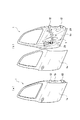
図1〜図6は本発明の第1実施形態を示し、図1はドアを分離して示す車体の全体斜視図、図2はドアを(a)に全体と(b)にドアアウターパネルを取外した状態でそれぞれ示す斜視図、図3はビーム部材の取り付け状態を示す平面図、図4はビーム部材の端部変形許容部を示す分解斜視図、図5は中腹部変形許容部を示す要部斜視図、図6はビーム部材の曲げ特性図である。 1 to 6 show a first embodiment of the present invention, FIG. 1 is an overall perspective view of a vehicle body with a door separated, and FIG. 2 shows an entire door in (a) and an outer door panel in (b). FIG. 3 is a plan view showing the mounting state of the beam member, FIG. 4 is an exploded perspective view showing the end portion deformable portion of the beam member, and FIG. 5 is a view showing the middle portion deformable portion. FIG. 6 is a partial perspective view, and FIG. 6 is a bending characteristic diagram of a beam member.
この第1実施形態の車両用ドアの補強構造は、図1に示すように、フロントドア1およびリアドア2を備えた自動車Mに適用され、ルーフ部3およびフロア部4の車幅方向両側にそれぞれ配置したサイドルーフレール5とサイドシル6とを、車体前後方向に適宜間隔をおいて配置した3本のピラー部材としてのフロントピラー7,センターピラー8およびリアピラー9によって車体上下方向に連結してある。
The vehicle door reinforcement structure of the first embodiment is applied to an automobile M having a
そして、これらサイドルーフレール5およびサイドシル6とフロントピラー7およびセンターピラー8とによって形成される前方の車体開口部10に前記フロントドア1を取り付けるとともに、サイドルーフレール5およびサイドシル6とセンターピラー8およびリアピラー9とによって形成される後方の車体開口部11に前記リアドア2を取り付けてある。
The
フロントドア1の前側縁を、上下2箇所のフロントヒンジ12を介してフロントピラー7に開閉自在に取り付けるとともに、リアドア2の前側縁を、上下2箇所のリアヒンジ13を介してセンターピラー8に開閉自在に取り付けてある。
The front side edge of the
また、フロントドア1の後側縁を、フロントストライカ14を介してセンターピラー8に係脱可能に連結するとともに、リアドア2の後側縁を、リアストライカ15を介してリアピラー9に係脱可能に連結してある。
Further, the rear side edge of the
図2(a)にフロントドア1を例にとってドア構造を示し、このフロントドア1の内部には、図2(b)に示すようにドアアウターパネル1aを取り外したドアインナーパネル1b側に、略車両前後方向に配置したビーム部材20を設けてある。
FIG. 2 (a) shows a door structure taking the
尚、前記ビーム部材20の取付け構造はリアドア2にあっても同様となるが、以下フロントドア1に例を取って説明するものとする。
The mounting structure of the
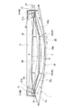
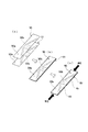
前記ビーム部材20は断面矩形状の閉断面に形成され、図3に示すようにその長さ方向(前後方向)両端部を、ブラケット21を介して上方のフロントヒンジ12とフロントストライカ14に各対応するインナーパネル1bの前後両側部に取り付けて、ドア1の閉止状態でビーム部材20の両端部を、前記ヒンジ12および前記ストライカ14を介してフロントピラー7とセンターピラー8に高い強度をもって支持してある。
The
ここで、本実施形態では前記ビーム部材20に、車両外方から内方へと略水平方向に作用する側面衝突入力をこのピラー部材20の長さ方向入力に変換・持続させる入力変換手段30を設けてある。
Here, in this embodiment, the
入力変換手段30は、図3に示すようにビーム部材20を車幅方向外方に湾曲させて、その中腹部に車両外方に凸となる頂点部Tを有する湾曲形状に形成することによって構成して、側面衝突荷重が前記頂点部Tに入力されるようにしてある。
The input conversion means 30 is configured by bending the
また、側面衝突荷重が入力するとビーム部材20は車幅方向内方に変形するが、本実施形態では側面衝突荷重により、車幅方向内方に変形するビーム部材20を略直線状態に形状保持する形状保持手段40を設けてある。
Further, when a side collision load is input, the
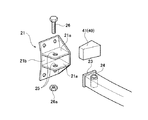
形状保持手段40は、図3,図4に示すようにビーム部材20の両端部に設けられて、このビーム部材20の車両外方壁面を支点に平面視して扇状に変形する端部変形許容部としてのエネルギー吸収体41と、図3,図5に示すようにビーム部材20の中腹部前後に設けられてビーム部材20の車両内方壁面を支点に平面視して扇状に変形する中腹部変形許容部としてのノッチ42と、を設けるとともに、図3に示すように前記各変形許容部41,42を除く部分の車室内側部と車室外側部の長さ方向壁面長L(L1+L2+L3)を、ビーム部材20の両端部の支持部材間スパンSと略同一長さに形成するとともに、前記各変形許容部41,42の圧縮強度をビーム部材本体部分20aの圧縮強度よりも低く設定することにより構成してある。
As shown in FIGS. 3 and 4, the
即ち、前記ビーム部材20の両端部は、上述したようにブラケット21を介してドア1のインナーパネル1bに取付けられるが、ブラケット21は、図4に示すようにビーム部材20の上下幅をもって一対の棚部21aを設けてアルミ合金等の軽合金鋳物として一体成形してある一方、ビーム部材20の端末には、圧縮荷重を伝達するためのエンドプレート23を結合するとともに、このビーム部材20の端部に上下方向に貫通するカラー24を溶接してある。
That is, both end portions of the
そして、ビーム部材20の端部を前記ブラケット21の棚部21a間に差込み、この棚部21aに形成した取付穴25と前記カラー24とを一致させて、これら取付穴25およびカラー24に枢軸となるボルト26を挿通してナット26a締めして連結してある。
Then, the end portion of the
このとき、ブラケット21の棚部21a間の奥側底面21bと前記エンドプレート23との間には平面扇形の空間部が形成され、この空間部の形状に沿って前記エネルギー吸収体41を扇形ブロック状に形成し、このエネルギー吸収体41を前記空間部に装填してある。このエネルギー吸収体41は、圧縮変形される素材、例えば発泡樹脂や発泡アルミニウムで形成してある。
At this time, a flat fan-shaped space portion is formed between the back
従って、ビーム部材20の両端部は前記ブラケット21を介してドア1のインナーパネル1aに回動自在に支持されるとともに、そのビーム部材20の両端部に前記エネルギー吸収体41が配置されることになる。
Accordingly, both end portions of the
一方、前記ノッチ42は、図5に示すように断面矩形状に形成したビーム部材20の車両外方の上下角部をV字状に凹設して形成してある。
On the other hand, as shown in FIG. 5, the
前記ビーム部材20に設けた入力変換手段30および形状保持手段40は、リアドア2に設けたビーム部材にあっても同様に構成される。
The input conversion means 30 and the
以上の構成によりこの第1実施形態によれば、フロントドア1ではビーム部材20は、頂点部Tを車幅方向外方に最も突出した部分として全体的に車体外方に湾曲し、その長さ方向両端部がブラケット21を介してドア1のインナーパネル1bに結合し、ドア1の閉止状態ではヒンジ12とストライカ14を介してフロントピラー7とセンターピラー8に強固に支持されている。
With the above configuration, according to the first embodiment, in the
尚、リアドア2ではビーム部材は、ヒンジ13とストライカ15を介してセンターピラー8とリアピラー9に強固に支持されることになる。
In the rear door 2, the beam member is firmly supported by the
従って、側面衝突時に入力される荷重をビーム部材20の頂点部Tで受け止め、このビーム部材20の両端部で前後に配置したフロントピラー7とセンターピラー8との間(リアドア2ではセンターピラー8とリアピラー9との間)で突っ張ることにより、衝突初期におけるドア反力をより早く発生させてドア1の変形を抑制する。
Accordingly, a load input at the time of a side collision is received at the apex T of the
また、ビーム部材20が頂点部Tを最突出部として湾曲しているため、このビーム部材20の長さ方向(前後方向)に圧縮力が作用した際には、車幅方向外方に凸となるモーメントが内力として誘起され、このモーメントは側面衝突時の衝突荷重によりビーム部材20を車幅方向内方に凸となるように作用する外力モーメントとは反対方向に作用して、この外力モーメントを打ち消すことにより、ビーム部材20に対する衝突荷重による負荷を軽減することができ、ひいては、衝突荷重に対するドア反力をより合理的に向上させることができる。
Further, since the
このため、ビーム部材20の両端部が突っ張ることによりドア反力を維持することができ、つまりは側面衝突による入力をビーム部材20の湾曲形状で構成する入力変換手段30により、ビーム部材20の長さ方向入力に変換・持続させるので、ビーム部材20の長手方向の圧縮荷重として入力吸収を行わせることができる。
For this reason, it is possible to maintain the door reaction force by stretching both ends of the
そして、側面衝突時の入力がビーム部材20の長さ方向の圧縮荷重として変換されて、この圧縮荷重がエネルギー吸収体41およびノッチ42の変形強度よりも大きい場合は、図3中破線に示すようにこれらエネルギー吸収体41およびノッチ42が圧潰変形し、これらの圧潰によっても衝突エネルギーを吸収する。
When the input at the time of the side collision is converted as a compressive load in the length direction of the
また、前記エネルギー吸収体41およびノッチ42の変形が完了すると、ビーム部材20の両端部において車体内方への回転が抑制され、ここに形状保持手段40としての機能が発揮されて、ビーム部材20を略直線状態に形状保持する。
Further, when the deformation of the
この結果、前記側面衝突時の入力荷重はフロントピラー7とセンターピラー8(リアドア2にあってはセンターピラー8とリアピラー9)に効率良く分散され、ビーム部材20、ひいてはドア1,2の車室内への進入を効果的に抑制することができる。
As a result, the input load at the time of the side collision is efficiently distributed to the front pillar 7 and the center pillar 8 (in the case of the rear door 2, the
更に、ビーム部材20は図3中破線に示す略直線状態の形状保持状態から側面衝突が更に進むと、部材長不変領域Rに張力が伝達され、前後のボルト26結合間を介してドア1,2の前後方向に位置するピラー7,8,9に荷重を伝達する。
Further, when the side collision of the
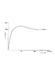
そして、張力の伝達が開始されるまでエネルギー吸収体41およびノッチ42では持続的に反力を発生するとともに、エネルギーを吸収することができ、これにより、ビーム部材20は図6に示すように理想的な曲げ特性を発揮することができる。
Then, the
従って、本実施形態では入力変換手段30によって側面衝突による入力荷重をビーム部材20の長さ方向入力に変換して持続させ、かつ、形状保持手段40によって車両内方に変形するビーム部材20を略直線状態に形状保持して、フロントドア1にあってはフロントピラー7とセンターピラー8、リアドア2にあってはセンターピラー8とリアピラー9に荷重分散させることができる。
Accordingly, in the present embodiment, the
また、本実施形態では前記入力変換手段30を、ビーム部材20を車幅方向外方に湾曲させて、その中腹部に車両外方に凸となる頂点部Tを有する湾曲形状として構成したので、ドア反力のより早い立上りと、入力の変換・持続作用を発揮させることができる。
Further, in the present embodiment, the input conversion means 30 is configured as a curved shape having the apex T that protrudes outward from the vehicle in the middle of the
一方、形状保持手段40は、ビーム部材20の両端部にエネルギー吸収体41で形成した端部変形許容部と、ビーム部材20の中腹部にノッチ42で形成した中腹部変形許容部とを設けて、ビーム部材20の長さ方向壁面長L(L1+L2+L3)を、ビーム部材20の両端部の支持部材間スパンSと略同一長さに形成するとともに、エネルギー吸収体41とノッチ42の圧縮強度をビーム部材本体部分20aの圧縮強度よりも低く設定することにより構成したので、ビーム部材20で長さ方向入力として変換された荷重が前記各変形許容部41,42の変形強度よりも大きくなると、これら変形許容部41,42を変形誘起部として確実に潰れ変形させて衝突エネルギーを吸収できるとともに、変形許容部41,42の変形完了によりビーム部材20を略直線状態に形状保持させて、前後のピラー7,8,9への荷重の分散を効率良く行わせることができる。
On the other hand, the shape holding means 40 is provided with an end portion deformable portion formed by the
また、前記ビーム部材20の両端変形許容部を構成するエネルギー吸収体41は、これを形成した素材の圧縮変形特性を適宜選定しておくことにより、また、ビーム部材20の中腹部変形許容部を構成するノッチ42は、その切り込み深さや切り込み幅を調節しておくことにより、要求特性に応じて変形開始点およびエネルギー吸収の調整を任意に設定することができる。
In addition, the
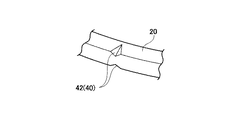
図7は本発明の第2実施形態を示し、前記実施形態と同一構成部分に同一符号を付して重複する説明を省略して述べるものとし、図7はビーム部材の中腹部分を示す斜視図である。 FIG. 7 shows a second embodiment of the present invention, in which the same components as those in the above embodiment are denoted by the same reference numerals and redundant description is omitted, and FIG. 7 is a perspective view showing the middle part of the beam member. It is.
本実施形態は中腹部変形許容部の変形例を示し、この中腹部変形許容部は、ビーム部材20の車両外側面から内側面に向かって平面V字状に切欠いたV字状切欠部43と、このV字状切欠部43を覆う蓋部材44(図中破線で示す)と、からなる平面三角状脆弱部45で形成してある。
The present embodiment shows a modification of the middle abdomen deformation allowance part, and this middle abdomen deformation allowance part includes a V-shaped
即ち、前記V字状切欠部43はそのV字状先端がビーム部材20の車両内側面に到達する深さに形成してあり、一方、前記蓋部材44はビーム部材本体部分20aよりも薄肉に形成され、これをV字状切欠部43の周縁部に溶接して結合してある。
That is, the V-shaped
従って、この実施形態にあっても、側面衝突時の入力がビーム部材20の長さ方向の圧縮荷重として変換されてV字状切欠部43に作用すると、蓋部材44を圧潰しつつV字状切欠部43の対向辺43aが近接しつつエネルギーを吸収し、そして、その対向辺43aが底付きした時点で形状保持手段40としての機能が発揮されて、ビーム部材20の車体内方への回転を抑制して略直線状態に形状保持することができる。
Accordingly, even in this embodiment, when the input at the time of a side collision is converted as a compressive load in the length direction of the
図8は本発明の第3実施形態を示し、前記各実施形態と同一構成部分に同一符号を付して重複する説明を省略して述べるものとし、図8はビーム部材の成型工程を(a)〜(c)に順を追って示す説明図である。 FIG. 8 shows a third embodiment of the present invention, in which the same components as those of the above-described embodiments are denoted by the same reference numerals and redundant description is omitted, and FIG. ) To (c) are explanatory views sequentially shown.
本実施形態では前記第2実施形態に示す三角状脆弱部45の変形例を示し、本実施形態の三角状脆弱部46は図8に示すように液圧成形でビーム部材20を成形する際に用いる2枚の差厚鋼板50,51で形成することができる。
In this embodiment, a modified example of the triangular
即ち、液圧成形によるビーム部材20は、図8(a)に示すように2枚の差厚鋼板50,51の両側縁部同士を、同図(b)に示すようにレーザ溶接して袋状に形成し、そして、同図(c)に示すようにこの袋状に形成した差厚鋼板50,51間に長さ方向両端部から高液圧を注入して所定形状、つまり、本実施形態では断面矩形状に膨出させるようになっている。
That is, the
このとき、前記差厚鋼板50,51は一般部50a,51aの肉厚をt1に形成する一方、これにV字状の肉厚部50b,51bを形成して、この肉厚部50b,51bの肉厚をt2(t2>t1)としておくことにより、液圧成形によりビーム部材20を成形完了した時点で前後2箇所の前記三角状脆弱部45が形成される。
At this time, the differential
ところで、本発明の車両用ドアの補強構造は第1〜第3実施形態に例をとって説明したが、これら実施形態に限ることなく本発明の要旨を逸脱しない範囲で他の実施形態を各種採用することができる。 By the way, although the reinforcement structure of the vehicle door of the present invention has been described with reference to the first to third embodiments, the present invention is not limited to these embodiments, and various other embodiments can be used without departing from the gist of the present invention. Can be adopted.
1 フロントドア
2 リアドア
3 ルーフ部
4 フロア部
5 サイドルーフレール
6 サイドシル
7 フロントピラー(ピラー部材)
8 センターピラー(ピラー部材)
9 リアピラー(ピラー部材)
20 ビーム部材
30 入力変換手段
40 形状保持手段
41 エネルギー吸収体(端部変形許容部)
42 ノッチ(中腹部変形許容部)
45,46 三角状脆弱部(中腹部変形許容部)
T 頂点部
DESCRIPTION OF
8 Center pillar (pillar member)
9 Rear pillar (pillar member)
20
42 notch (middle abdominal deformation allowance)
45,46 Triangular weak part (middle abdomen deformation allowable part)
T vertex
Claims (6)
前記ビーム部材に、車両外方から内方へと略水平方向に作用する側面衝突入力をこのピラー部材の長さ方向入力に変換・持続させる入力変換手段と、
前記側面衝突入力により車幅方向内方に変形するビーム部材を略直線状態に形状保持する形状保持手段と、を設けたことを特徴とする車両用ドアの補強構造。 Side roof rails and side sills arranged on both sides of the roof part and floor part in the vehicle width direction are connected in the vertical direction of the vehicle body by a plurality of pillar members arranged at appropriate intervals in the vehicle body longitudinal direction. A vehicle body structure in which a door is attached to a vehicle body opening formed by front and rear pillar members, and a beam member straddling both longitudinal ends of the front and rear pillar members is provided inside the door,
Input conversion means for converting and sustaining a side collision input acting on the beam member in a substantially horizontal direction from the outside of the vehicle to the inside thereof into a length direction input of the pillar member;
A vehicle door reinforcing structure comprising: a shape holding means for holding the beam member deformed inward in the vehicle width direction by the side collision input in a substantially linear state.
6. The middle abdomen deformable portion comprises a notch formed by recessing an upper and lower corner of the beam member formed in a rectangular cross section in a V shape. The vehicle door reinforcement structure according to one.
Priority Applications (1)
| Application Number | Priority Date | Filing Date | Title |
|---|---|---|---|
| JP2004119301A JP2005297856A (en) | 2004-04-14 | 2004-04-14 | Vehicle door reinforcement structure |
Applications Claiming Priority (1)
| Application Number | Priority Date | Filing Date | Title |
|---|---|---|---|
| JP2004119301A JP2005297856A (en) | 2004-04-14 | 2004-04-14 | Vehicle door reinforcement structure |
Publications (1)
| Publication Number | Publication Date |
|---|---|
| JP2005297856A true JP2005297856A (en) | 2005-10-27 |
Family
ID=35329914
Family Applications (1)
| Application Number | Title | Priority Date | Filing Date |
|---|---|---|---|
| JP2004119301A Pending JP2005297856A (en) | 2004-04-14 | 2004-04-14 | Vehicle door reinforcement structure |
Country Status (1)
| Country | Link |
|---|---|
| JP (1) | JP2005297856A (en) |
Cited By (4)
| Publication number | Priority date | Publication date | Assignee | Title |
|---|---|---|---|---|
| JP2011057176A (en) * | 2009-09-14 | 2011-03-24 | Daihatsu Motor Co Ltd | Side door device of vehicle |
| JP2015047952A (en) * | 2013-08-30 | 2015-03-16 | スズキ株式会社 | Bracket structure for vehicle door beam |
| JP2021054246A (en) * | 2019-09-30 | 2021-04-08 | 株式会社Subaru | Vehicle body structure |
| CN115139763A (en) * | 2021-03-31 | 2022-10-04 | 本田技研工业株式会社 | Vehicle door anti-collision beam structure |
-
2004
- 2004-04-14 JP JP2004119301A patent/JP2005297856A/en active Pending
Cited By (7)
| Publication number | Priority date | Publication date | Assignee | Title |
|---|---|---|---|---|
| JP2011057176A (en) * | 2009-09-14 | 2011-03-24 | Daihatsu Motor Co Ltd | Side door device of vehicle |
| JP2015047952A (en) * | 2013-08-30 | 2015-03-16 | スズキ株式会社 | Bracket structure for vehicle door beam |
| JP2021054246A (en) * | 2019-09-30 | 2021-04-08 | 株式会社Subaru | Vehicle body structure |
| JP7284055B2 (en) | 2019-09-30 | 2023-05-30 | 株式会社Subaru | car body structure |
| CN115139763A (en) * | 2021-03-31 | 2022-10-04 | 本田技研工业株式会社 | Vehicle door anti-collision beam structure |
| JP2022155887A (en) * | 2021-03-31 | 2022-10-14 | 本田技研工業株式会社 | door beam structure |
| US11820211B2 (en) | 2021-03-31 | 2023-11-21 | Honda Motor Co., Ltd. | Door beam structure |
Similar Documents
| Publication | Publication Date | Title |
|---|---|---|
| JP4059187B2 (en) | Vehicle hood structure | |
| JP5755258B2 (en) | Body side structure | |
| JP7408927B2 (en) | Vehicle rear body structure | |
| US6983981B2 (en) | Vehicle body structure | |
| JP5549420B2 (en) | Rear body structure of the vehicle | |
| CN106995011A (en) | Vehicle body front structure | |
| JP2015229384A (en) | Vehicle front structure | |
| JP2007038839A (en) | Rear part car body structure for vehicle | |
| JP6600873B2 (en) | Body structure | |
| CN108495777A (en) | Front part structure of vehicle | |
| JP2004123027A (en) | Body front structure | |
| US8292353B2 (en) | Construction for an automotive vehicle | |
| JP5396945B2 (en) | Lower body structure of the vehicle | |
| JP2010120525A (en) | Vehicle body lower structure | |
| KR20210012339A (en) | Front body structure of vehicle | |
| JP2004106808A (en) | Body front structure | |
| JP2005297857A (en) | Bumper reinforcement structure | |
| JP4715467B2 (en) | Body front structure | |
| JP2009154859A (en) | Body front structure | |
| JP2003054452A (en) | Car body front structure | |
| JP2005297856A (en) | Vehicle door reinforcement structure | |
| JP6016246B2 (en) | Auto body structure | |
| CN111989258B (en) | Automobile body structure | |
| JP2003170862A (en) | Body front structure | |
| WO2019198751A1 (en) | Body structure for automobiles |