JP2005297830A - Body front structure - Google Patents
Body front structure Download PDFInfo
- Publication number
- JP2005297830A JP2005297830A JP2004118531A JP2004118531A JP2005297830A JP 2005297830 A JP2005297830 A JP 2005297830A JP 2004118531 A JP2004118531 A JP 2004118531A JP 2004118531 A JP2004118531 A JP 2004118531A JP 2005297830 A JP2005297830 A JP 2005297830A
- Authority
- JP
- Japan
- Prior art keywords
- subframe
- bending
- start position
- side member
- vehicle body
- Prior art date
- Legal status (The legal status is an assumption and is not a legal conclusion. Google has not performed a legal analysis and makes no representation as to the accuracy of the status listed.)
- Granted
Links
Images
Landscapes
- Body Structure For Vehicles (AREA)
Abstract
Description
本発明は、エンジンユニットを搭載収納するフロントコンパートメントの構造に関し、車体の前面衝突時に前方からの衝撃を受け、これを吸収する車体前部構造に関する。 The present invention relates to a structure of a front compartment that mounts and stores an engine unit, and relates to a vehicle body front structure that receives and absorbs an impact from the front when a frontal collision of a vehicle body occurs.
一般に自動車の車体において、エンジン等のエンジンユニット部品を収容するフロントコンパートメントの左右両側に、車体前後方向に延在する一対のサイドメンバが配設され、これらのサイドメンバの下側に、エンジンユニット部品を搭載支持する一対のサブフレームが配設されており、車体の前面衝突時に前方から過大な衝撃を受けた際、前記サイドメンバおよびサブフレームなどにより衝撃を吸収してフロアフレームなどを介して衝撃エネルギの分散を図るようにしている。 In general, in a vehicle body, a pair of side members extending in the longitudinal direction of the vehicle body are disposed on the left and right sides of a front compartment that accommodates an engine unit component such as an engine, and the engine unit components are disposed below these side members. A pair of sub-frames for mounting and supporting are installed, and when an excessive impact is received from the front during a frontal collision of the vehicle body, the impact is absorbed by the side members and the sub-frames and the like through the floor frame. The energy is distributed.
この種の従来技術としては、車体の前面衝突時に前方からの衝突荷重をサイドメンバおよびサブフレームにほぼ同時に掛けることにより、衝突初期段階からサブフレームをサイドメンバと共にエネルギ吸収部材として機能させるようにしたものが挙げられる(例えば、特許文献1参照。)。 In this type of conventional technology, a collision load from the front is applied to the side member and the sub frame almost simultaneously at the time of a frontal collision of the vehicle body, so that the sub frame functions as an energy absorbing member together with the side member from the initial stage of the collision. (For example, refer to Patent Document 1).
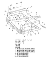
図6はこの種の従来の車体前部構造を示す斜視図で、この図6において、フロントコンパートメント1の左右両側に配設され、車体前後方向に延在する一対のサイドメンバ2と、これらのサイドメンバ2の下側にそれぞれ配置され、図示しないエンジンユニット部品を搭載支持する一対のサブフレーム3とを有している。サイドメンバ2は、車体前後方向の前側に位置する水平部4、およびこの水平部4の後端部から後下がりに傾斜する傾斜部5により一体的に形成されており、この傾斜部5の後端部には、サブフレーム3の後端部が接合されると共に、図示しないダッシュパネルの前面からフロア下面に廻り込んで車体前後方向に延在するエクステンションメンバ6も接合されている。
FIG. 6 is a perspective view showing a conventional vehicle body front structure of this type. In FIG. 6, a pair of
サイドメンバ2の前端部、すなわち水平部4の前端部には、クロージングプレート7を介して図示しないバンパステイが前方へ突出する状態で設けられると共に、左右のサブフレーム3の前端部間に車幅方向に延在するファーストクロスメンバ8が設けられ、水平部4の前端部およびサブフレーム3の前端部の間は連結体9で連結されている。
ところで、上記した従来技術にあっては、車体の前面衝突時に前方からの衝突荷重をサイドメンバ2およびサブフレーム3にほぼ同時に掛けることにより、衝突初期段階からサブフレーム3をサイドメンバ2と共に圧潰変形して衝突エネルギを吸収する。サブフレーム3のみが圧潰変形するものと比べて車体の衝撃吸収効率を向上できるが、過大な衝撃力が掛かった場合に瞬間的にサイドメンバ2の後端部近傍より前方の車体の前部が下がると共に後部が上る挙動、いわゆるノーズダイブおよび尻上り現象が生じるという問題があった。その結果、車体の前部が下がると共に運転室前部のダッシュパネルやダッシュ上部が下がるため、これらのダッシュパネルやダッシュ上部がエンジンユニットと干渉するおそれがあり、これらのダッシュパネルやダッシュ上部を補強する必要があった。
By the way, in the above-described prior art, the collision load from the front is applied to the
また、上記のように車体の前部が下がることに伴って運転室のフロントピラーやシルも下降するが、前輪タイヤは地面に接しており下降動作が規制されるので、前輪タイヤからの荷重が働く高さ位置がシルの位置より上方にずれるおそれがあり、この状態で前輪タイヤがフロントピラーに干渉するという問題もあった。その結果、前輪タイヤからの荷重がシルの軸方向に掛からないのでフロントピラーに比較的大きな荷重が掛かり、このため、フロントピラーの補強が必要であるがシルより断面が小さいため補強効果が少なかった。 In addition, as the front part of the vehicle body is lowered as described above, the front pillar and sill of the cab are also lowered, but the front wheel tire is in contact with the ground and the lowering operation is restricted, so the load from the front wheel tire is There is a possibility that the working height position may be shifted upward from the position of the sill. In this state, there is also a problem that the front wheel tire interferes with the front pillar. As a result, since the load from the front tire is not applied in the axial direction of the sill, a relatively large load is applied to the front pillar. For this reason, the front pillar needs to be reinforced, but the reinforcing effect is small because the cross section is smaller than the sill. .
本発明は、上記のような従来技術を考慮してなされたもので、その目的は、車体の前面衝突時に衝突荷重を確実に吸収できると共に、運転室のダッシュ部分やシルが下がることを防止できる車体前部構造を提供することにある。 The present invention has been made in consideration of the above-described prior art, and the object thereof is to reliably absorb a collision load at the time of a frontal collision of a vehicle body and to prevent a dash portion or a sill of a cab from being lowered. The object is to provide a front body structure.
上記目的を達成するために請求項1に記載の発明は、フロントコンパートメントの左右両側に配設され、車体前後方向に延在するサイドメンバと、これらのサイドメンバの下側にそれぞれ配置されるサブフレームとを有し、前記サイドメンバを、車体前後方向の前側に位置する水平部、およびこの水平部の後端部から後下がりに傾斜する傾斜部により一体的に形成し、前記サイドメンバの水平部に対して前記サブフレームを略平行に配置すると共に、前記サブフレームの前端部を所定長さの連結体を介して前記水平部の前端部と連結し、前記サブフレームの後端部を前記傾斜部と連結した車体前部構造において、
前記サイドメンバの上面の前記連結体の直後に折曲げ助長手段を設けた第1折曲り開始位置と、前記サイドメンバの下面の前記水平部と前記傾斜部との界位置に折曲げ助長手段を設けた第2折曲り開始位置と、前記サブフレームの上面の先端と根元との中間位置に折曲げ助長手段を設けた第3折曲り開始位置とをそれぞれ特定した構成にした。
In order to achieve the above object, a first aspect of the present invention provides a side member disposed on the left and right sides of the front compartment, extending in the longitudinal direction of the vehicle body, and a sub-member disposed below each of the side members. The side member is integrally formed by a horizontal portion located on the front side in the longitudinal direction of the vehicle body and an inclined portion inclined downward from the rear end portion of the horizontal portion. The subframe is disposed substantially parallel to the portion, the front end portion of the subframe is connected to the front end portion of the horizontal portion via a connecting body having a predetermined length, and the rear end portion of the subframe is In the front structure of the vehicle body connected to the inclined part
Bending assisting means is provided at a first bending start position in which bending facilitating means is provided immediately after the coupling body on the upper surface of the side member, and at a boundary position between the horizontal part and the inclined part on the lower surface of the side member. The second bending start position provided and the third bending start position provided with a bending facilitating means at an intermediate position between the tip and root of the upper surface of the subframe are specified.
このように構成した請求項1に記載の発明では、前面衝突時に前方からの衝突荷重をサイドメンバおよびサブフレームで受ける際、サイドメンバ上面の第1折曲り開始位置で折曲りが開始して上向きの曲げモーメントが生じると共に、サイドメンバ下面の第2折曲り開始位置で折曲りが開始して下向きの曲げモーメントが生じ、その結果、サイドメンバが第1折曲り開始位置および第2折曲り開始位置で上下方向に折曲り変形する。同時に、サブフレーム上面の第3折曲り開始位置で折曲りが開始して上向きの曲げモーメントが生じると共に、サブフレーム後端の連結部でも折曲り、その結果、サブフレームも第3折曲り開始位置および後端の連結部で上下方向に折曲り変形する。すなわち、側方からみて平行四辺形で、全体としてエンジンユニットを囲う平行四辺形状を保持して変形する。これにより、車体の前面衝突時にサイドメンバおよびサブフレームの上下方向への折曲り変形で衝突荷重を上方向と下方向の分力に分散して確実に吸収できると共に、前記サイドメンバおよびサブフレームの折曲り変形により運転室より前方のフレームやメンバが部分的に下がるがタイヤ高さは不変であるので、運転室のダッシュ部分やシルが下がらず所望の力の伝達が図られ、エンジンユニットとの干渉等を防ぐことができる。
In the invention according to
また、請求項2に記載の発明は、請求項1に記載の発明において、前記第1折曲り開始位置から第2折曲り開始位置までの寸法と、前記第3折曲り開始位置から前記サブフレームの後端の連結部までの寸法とを同等に設定した構成にした。 According to a second aspect of the present invention, in the first aspect of the present invention, the dimension from the first bend start position to the second bend start position and the third bend start position to the subframe. It was set as the structure which set to the dimension to the connection part of the rear end equally.
このように構成した請求項2に記載の発明では、サイドメンバの水平部に対してサブフレームが略平行に配置されると共に、第1折曲り開始位置から第2折曲り開始位置までの寸法と、第3折曲り開始位置からサブフレームの後端の連結部までの寸法とを等しくしたため、これらの第1折曲り開始位置、第2折曲り開始位置、第3折曲り開始位置およびサブフレーム後端の連結部との4点で平行四辺形が形成される。これによって、前面衝突時に前方からの衝突荷重をサイドメンバおよびサブフレームで受ける際、サイドメンバの水平部に対してサブフレームが略平行な状態を保ったまま、すなわち平行四辺形を保ってサイドメンバおよびサブフレームが折曲がるので、サイドメンバおよびサブフレーム間にエンジンユニット部品の設置スペースを確保することができる。
In the invention according to
また、請求項3に記載の発明は、請求項1に記載の発明において、前記第1折曲げ助長手段は、溝形状である構成にした。
The invention according to
このように構成した請求項3に記載の発明では、折曲げ助長手段を溝形状としたので、製造容易で、かつ折曲げ容易であり、所望の位置での折曲げ変形を得ることができる。
In the invention according to
また、請求項4に記載の発明は、フロントコンパートメントの左右両側に配設され、車体前後方向に延在するサイドメンバと、これらのサイドメンバの下側にそれぞれ配置されるサブフレームとを有し、前記サイドメンバを、車体前後方向の前側に位置する水平部、およびこの水平部の後端部から後下がりに傾斜する傾斜部により一体的に形成し、前記サイドメンバの水平部に対して前記サブフレームを略平行に配置すると共に、前記サブフレームの前端部を所定長さの連結体を介して前記水平部の前端部と連結し、前記サブフレームの後端部を前記傾斜部と連結した車体前部構造において、
前記サイドメンバの下面の前記連結体との接合位置に第1補強部を設けることにより、前記第1補強部の反対側の前記サイドメンバの上面に前記第4折曲り開始位置を形成し、前記サイドメンバの上面の前記水平部と前記傾斜部との界位置に第2補強部を設けることにより、前記第2補強部の反対側の前記サイドメンバの下面に前記第5折曲り開始位置を形成し、前記サブフレームの下面先端と根元との中間位置に第3補強部を設けることにより、前記第3補強部の反対側の前記サブフレームの上面に前記第6折曲り開始位置を形成するように構成した。
According to a fourth aspect of the present invention, there is provided a side member disposed on the left and right sides of the front compartment and extending in the longitudinal direction of the vehicle body, and a sub-frame disposed below each of the side members. The side member is integrally formed by a horizontal portion located on the front side in the longitudinal direction of the vehicle body and an inclined portion inclined downward from the rear end portion of the horizontal portion, and the side member is formed with respect to the horizontal portion of the side member. The sub-frame is arranged substantially in parallel, the front end of the sub-frame is connected to the front end of the horizontal portion via a connecting body having a predetermined length, and the rear end of the sub-frame is connected to the inclined portion. In the body front structure,
By providing a first reinforcing portion at a position where the lower surface of the side member is joined to the connector, the fourth bending start position is formed on the upper surface of the side member on the opposite side of the first reinforcing portion, The fifth bending start position is formed on the lower surface of the side member opposite to the second reinforcing portion by providing a second reinforcing portion at a boundary position between the horizontal portion and the inclined portion on the upper surface of the side member. The sixth bending start position is formed on the upper surface of the subframe opposite to the third reinforcing portion by providing the third reinforcing portion at an intermediate position between the lower surface tip and the base of the subframe. Configured.
このように構成した請求項4に記載の発明では、サイドメンバ下面の所定位置が第1補強部により補強され、この部分の剛性が比較的大きいので、前方からの衝突荷重を受ける際に前記サイドメンバ下面の所定位置の圧縮応力とこれに対向する上面の圧縮応力との差が生じて上向きの曲げモーメントが生じる結果、第4折曲り開始位置でサイドメンバの上面の折曲りが開始する。同様に、サイドメンバの上面の所定位置が第2補強部により補強されているので、第5折曲り開始位置でサイドメンバの下面の折曲りが開始し、さらにサブフレームの下面の所定位置が第3補強部で補強されているので、第6折曲り開始位置でもサブフレームの上面の折曲りが開始する。これによって、前方からの衝突荷重によりサイドメンバを第4折曲り開始位置および第5折曲り開始位置で上下方向に折曲り変形させることができると共に、サブフレームも第6折曲り開始位置および後端の連結部で上下方向に折曲り変形させることができる。
In the invention according to
以上説明したように本発明では、車体の前面衝突時に衝突荷重をサイドメンバおよびサブフレームの上下方向への折曲り変形で上方向と下方向の分力に分散して確実に吸収できると共に、前記サイドメンバおよびサブフレームの折曲り変形により運転室より前方のみが部分的に下がるので、運転室のダッシュ部分やシルが下がることを防止できる。 As described above, in the present invention, the collision load can be reliably absorbed by being distributed to the upward and downward component forces by bending the side member and the subframe in the vertical direction at the time of a frontal collision of the vehicle body. Since only the front part of the cab is partially lowered due to the bending deformation of the side member and the subframe, it is possible to prevent the dash part and the sill of the cab from being lowered.
以下、本発明の車体前部構造の実施形態を図に基づいて説明する。 Hereinafter, an embodiment of a vehicle body front structure according to the present invention will be described with reference to the drawings.
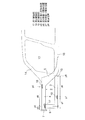
図1は本発明の第1実施形態に係わる車体前部構造を示す図、図2は図1の車体前部構造に設けられる各折曲り溝を拡大して示す斜視図、図3は本実施形態に設けられるサイドメンバおよびサブフレームを模式的に示す図、図4は本実施形態に設けられるサイドメンバおよびサブフレームが折曲り変形した状態を示す図である。なお、図1〜図4において前述した図6に示すものと同等のものには同一符号を付してある。 FIG. 1 is a diagram showing a vehicle body front structure according to the first embodiment of the present invention, FIG. 2 is an enlarged perspective view showing each bending groove provided in the vehicle body front structure of FIG. 1, and FIG. FIG. 4 is a diagram schematically illustrating a side member and a sub frame provided in the embodiment, and FIG. 4 is a diagram illustrating a state in which the side member and the sub frame provided in the present embodiment are bent and deformed. In FIG. 1 to FIG. 4, the same components as those shown in FIG.
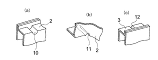
図1に示す本実施形態の車体前部構造は、前述した図6に示すものと比べて、サイドメンバ2の水平部4に対してサブフレーム3を略平行に配置し、第1折曲り開始位置p1でサイドメンバ2の上面に折曲げ助長手段である第1折曲り溝10を形成し、第2折曲り開始位置p2でサイドメンバ2の下面に折曲げ助長手段である第2折曲り溝11を形成し、第3折曲り開始位置P3でサブフレーム3の上面に折曲げ助長手段である第3折曲り溝12を形成したことが異なっており、その他の構成は基本的に同様である。
The vehicle body front part structure of the present embodiment shown in FIG. 1 has the
図2の(a)に示すように第1折曲り溝10は、車体幅方向に延在する、断面半円、U字、V字等凹状の成型ビードからなり、サイドメンバ2の上面の第1折曲り開始位置p1を構成し、図2の(b)に示すように第2折曲り溝11は、車体幅方向に延在する前述のような凹状の成型ビードからなり、サイドメンバ2の下面の第2折曲り開始位置p2を構成する。同様に図2の(c)に示すように第3折曲り溝12は、車体幅方向に延在する前述のような凹状の成型ビードからなり、サブフレーム3の上面の第3折曲り開始位置p3を構成している。
As shown in FIG. 2 (a), the first
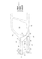
また、第1折曲り開始位置p1は、サイドメンバ2の前端部(すなわち水平部4の前端部)の連結体9の直後に配置され、該前端部から比較的少ない所定寸法d1離間している。図3に示すように第2折曲り開始位置p2は、運転室13のフロントピラー14の直前の水平部4と傾斜部5との界に配置され、第1折曲り開始位置p1より所定寸法d2後方に離間している。第3折曲り開始位置p3は、サブフレーム3の中間位置で前端部から所定寸法d3離間し、第1折曲り開始位置p1より後方で、かつ第2折曲り開始位置p2より前方に位置している。そして、第1折曲り開始位置p1から第2折曲り開始位置p2までの寸法d2と、第3折曲り開始位置p3からサブフレーム3の後端位置p4までの寸法d4とが同等に設定されている。上記のように寸法d2と寸法d4とが同等であり、しかもサイドメンバ2の水平部4に対してサブフレーム3が略平行に配置されているため、第1折曲り開始位置p1、第2折曲り開始位置p2、第3折曲り開始位置p3およびサブフレーム3後端の連結部15との4点で平行四辺形が形成されている。
The first bending start position p1 is disposed immediately after the connecting
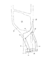
この実施形態にあっては、図4の2点鎖線で示す通常状態で車体の前面衝突時に前方からの衝突荷重をサイドメンバ2およびサブフレーム3で受ける際、第1折曲り溝10でサイドメンバ2の上面の折曲りを開始すると共に、第2折曲り溝11でサイドメンバ2の下面の折曲りを開始する。同時に、第3折曲り溝12でサブフレーム3の上面の折曲りを開始すると共に、サブフレーム3の後端の連結部15でも折曲りを開始する。その結果、図4の実線で示すようにサイドメンバ2が第1折曲り開始位置p1および第2折曲り開始位置p2で上下方向に折曲り変形し、サブフレーム3も第3折曲り開始位置p3および後端位置p4で上下方向に折曲り変形する。このとき、前記折曲り開始位置p1〜p3およびサブフレーム3後端の連結部15との4点で平行四辺形が形成されているため、サイドメンバ2の水平部4に対してサブフレーム3が略平行な状態に保たれる。
In this embodiment, when a collision load from the front is received by the
このように構成した本実施形態では、車体の前面衝突時にサイドメンバ2およびサブフレーム3の上下方向への折曲り変形で衝突荷重を上方向と下方向の分力に分散して確実に吸収できると共に、サイドメンバ2およびサブフレーム3の折曲り変形により運転室13より前方のみ部分的に下がるので、運転室13の図示しないダッシュ部分やシル16が下がることを防止できる。当然ながら、タイヤ高さは変わらないので、タイヤとシル16とは所望の高さで突き当たり、シル16はタイヤの力を効率的に受ける。
In the present embodiment configured as described above, the collision load can be reliably absorbed by the upward and downward component forces by the bending deformation of the
また、本実施形態では、サイドメンバ2の前端部の直後とフロントピラー14の直前とでサイドメンバ4を折曲げるようにしたので、これらの折曲り開始位置p1、p2の間隔を比較的大きく設定でき、さらに、サイドメンバ2の水平部4に対してサブフレーム3が略平行な状態を保ったままサイドメンバ2およびサブフレーム3が上下方向へ折曲がるので、サイドメンバ2の折曲り開始位置p1、p2間およびサブフレーム3間の折曲り開始位置p3,p4間に図示しないエンジンユニット部品を収納するスペースを確保することができる。
In this embodiment, since the
なお、上記実施形態にあっては、略直線状に形成したサブフレーム3を図示したが、折曲り開始位置p1〜p3およびサブフレーム3後端の連結部15の4点で平行四辺形が形成されるならば、その他の形状、例えば曲線状のものであってもよい。
In addition, in the said embodiment, although the
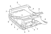
図5は本発明の第2実施形態に係わる車体前部構造のサイドメンバおよびサブフレームを模式的に示す図である。なお、図5において前述した図1〜図4および図6に示すものと同等のものには同一符号を付してある。 FIG. 5 is a view schematically showing a side member and a subframe of the vehicle body front structure according to the second embodiment of the present invention. In FIG. 5, the same components as those shown in FIGS. 1 to 4 and FIG.
図5に示す本実施形態の車体前部構造は、前述した図1〜図4に示すものと比べて、折曲げ助長手段である第1折曲り溝10〜第3折曲り溝12を形成する代わりに、それぞれの反対面側に補強をし、補強をしない反対側を折曲げさせるものである。すなわちサイドメンバ2の連結体9との接合位置に第1補強部17を設け、サイドメンバ2の下面の水平部4と傾斜部5との界位置の反対側に第2補強部18を設け、サブフレーム3の下面の先端と根元の中間位置に第3補強部19を設けたことが異なっており、その他の構成は基本的に同様である。
The vehicle body front part structure of the present embodiment shown in FIG. 5 forms the
この実施形態の車体前部構造にあっては、サイドメンバ2下面の所定位置が第1補強部17により補強され、この部分の剛性が比較的大きいので、前方からの衝突荷重を受ける際にサイドメンバ2下面の所定位置の圧縮応力とこれに対向する上面の圧縮応力との差が生じて上向きの曲げモーメントが生じる結果、第4折曲り開始位置p5でサイドメンバ2の上面の折曲りが開始する。同様に、サイドメンバ2の上面の所定位置が第2補強部18により補強されているので、第5折曲り開始位置p6でサイドメンバ2の下面の折曲りが開始し、さらにサブフレーム3の下面の所定位置が第3補強部19で補強されているので、第6折曲り開始位置p7でもサブフレーム3の上面の折曲りが開始する。その結果、前方からの衝突荷重によりサイドメンバ2が第4折曲り開始位置p5および第5折曲り開始位置p6で上下方向に折曲り変形すると共に、サブフレーム3も第6折曲り開始位置p7および後端の連結部15で上下方向に折曲り変形する。
In the vehicle body front structure of this embodiment, a predetermined position on the lower surface of the
第3補強部19は、サイドメンバ2の下面に密着するように該下面の下側に設けてもよく、また、サイドメンバ2の下面の側部や下面の内側(上側)に設けることもできる。第2補強部18はサイドメンバ2の上面に設けられ、第1補強部17は 、連結部9の上端を上方へ延ばしてサブフレーム4の下面の側部に密着させることにより一体的に形成されている。しかしながら、連結部9の上端側部およびサブフレーム3の下面の側部に密着するパッチ板によりサブフレーム3の下面を補強することもできる。あるいはサブフレーム3の下面に密着するように該下面の下側に設けたり、下面の側部や下面の内側(上側)に設けてもよい。ここでの補強は、パッチを溶接で当てたり、L型、U型のレインフォース等を溶接で当ててもよい。
The third reinforcing
また、第4折曲り開始位置p5は、サイドメンバ2の前端部(すなわち水平部4の前端部)の近傍に配置され、該前端部から比較的小さな寸法d5だけ離間している。第5折曲り開始位置p6は運転室13のフロントピラー14の直前に配置され、第4折曲り開始位置p5より寸法d6後方に離間している。第6折曲り開始位置p7は、サブフレーム3の前端部のから寸法d7離間し、第4曲り開始位置p5より後方で、かつ第5折曲り開始位置p6より前方に位置している。そして、第4折曲り開始位置p5から第5折曲り開始位置p6までの寸法d6と、第6折曲り開始位置p7からサブフレーム3の後端位置p8までの寸法d8とが等しく設定されている。
The fourth bending start position p5 is disposed in the vicinity of the front end portion of the side member 2 (that is, the front end portion of the horizontal portion 4), and is separated from the front end portion by a relatively small dimension d5. The fifth bending start position p6 is disposed immediately before the
このように構成した本実施形態でも、前述した図1、図2に示すものと同様の効果が得られる。 Even in the present embodiment configured as described above, the same effects as those shown in FIGS. 1 and 2 can be obtained.
なお、上記実施形態にあっては、第1補強部17および第2補強部18をサイドメンバ2に設け、第3補強部19をサブフレーム3に設けたので、これらのサイドメンバ2およびサブフレーム3の強度が全体的にみて一般部が相対的に弱くなっており、前方からの衝突荷重を受けた際にサイドメンバ2およびサブフレーム3が円滑に上下方向へ折曲り所望の変形が可能である。
In the above embodiment, since the first reinforcing
1 フロントコンパートメント
2 サイドメンバ
3 サブフレーム
4 水平部
5 傾斜部
9 連結体
10 第1折曲り溝(折曲り助長手段)
11 第2折曲り溝(折曲り助長手段)
12 第3折曲り溝(折曲り助長手段)
13 運転室
15 連結部
17 第1補強部
18 第2補強部
19 第3補強部
p1 第1折曲り開始位置
p2 第2折曲り開始位置
p3 第3折曲り開始位置
p4 後端位置
p5 第4折曲り開始位置
p6 第5折曲り開始位置
p7 第6折曲り開始位置
p8 後端位置
DESCRIPTION OF
11 Second bend groove (bending aid)
12 3rd bending groove (bending aid)
13
Claims (4)
前記サイドメンバの上面の前記連結体の直後に折曲げ助長手段を設けた第1折曲り開始位置と、前記サイドメンバの下面の前記水平部と前記傾斜部との界位置に折曲げ助長手段を設けた第2折曲り開始位置と、前記サブフレームの上面の、先端と根元との中間位置に折曲げ助長手段を設けた第3折曲り開始位置とをそれぞれ特定したことを特徴とする車体前部構造。 It has side members arranged on the left and right sides of the front compartment and extending in the longitudinal direction of the vehicle body, and sub-frames arranged on the lower sides of these side members, and the side members are connected to the front side in the longitudinal direction of the vehicle body. And a horizontal portion positioned at the rear portion of the horizontal portion, and an inclined portion inclined downwardly from the rear end portion of the horizontal portion, and the subframe is disposed substantially parallel to the horizontal portion of the side member, and In the vehicle body front structure in which the front end portion of the subframe is connected to the front end portion of the horizontal portion via a connecting body having a predetermined length, and the rear end portion of the subframe is connected to the inclined portion.
Bending assisting means is provided at a first bending start position in which bending facilitating means is provided immediately after the coupling body on the upper surface of the side member, and at a boundary position between the horizontal part and the inclined part on the lower surface of the side member. A vehicle body front characterized by specifying a second bending start position provided and a third bending start position provided with a bending promoting means at an intermediate position between the tip and the base of the upper surface of the subframe. Part structure.
前記サイドメンバの下面の前記連結体との接合位置に第1補強部を設けることにより、前記第1補強部の反対側の前記サイドメンバの上面に前記第4折曲り開始位置を形成し、前記サイドメンバの上面の前記水平部と前記傾斜部との界位置に第2補強部を設けることにより、前記第2補強部の反対側の前記サイドメンバの下面に前記第5折曲り開始位置を形成し、前記サブフレームの下面先端と根元との中間位置に第3補強部を設けることにより、前記第3補強部の反対側の前記サブフレームの上面に前記第6折曲り開始位置を形成するようにしたことを特徴とする車体前部構造。 It has side members arranged on the left and right sides of the front compartment and extending in the longitudinal direction of the vehicle body, and sub-frames arranged on the lower sides of these side members, and the side members are connected to the front side in the longitudinal direction of the vehicle body. And a horizontal portion located at the rear portion of the horizontal portion, and an inclined portion inclined downward from the rear end portion of the horizontal portion, and the subframe is disposed substantially parallel to the horizontal portion of the side member, and In the vehicle body front structure in which the front end portion of the subframe is connected to the front end portion of the horizontal portion via a connecting body having a predetermined length, and the rear end portion of the subframe is connected to the inclined portion.
By providing a first reinforcing portion at a position where the lower surface of the side member is joined to the connector, the fourth bending start position is formed on the upper surface of the side member on the opposite side of the first reinforcing portion, By providing a second reinforcing portion at a boundary position between the horizontal portion and the inclined portion on the upper surface of the side member, the fifth bending start position is formed on the lower surface of the side member opposite to the second reinforcing portion. The sixth bending start position is formed on the upper surface of the subframe opposite to the third reinforcing portion by providing the third reinforcing portion at an intermediate position between the tip and the bottom of the lower surface of the subframe. A vehicle body front structure characterized by the fact that
Priority Applications (1)
| Application Number | Priority Date | Filing Date | Title |
|---|---|---|---|
| JP2004118531A JP4379186B2 (en) | 2004-04-14 | 2004-04-14 | Body front structure |
Applications Claiming Priority (1)
| Application Number | Priority Date | Filing Date | Title |
|---|---|---|---|
| JP2004118531A JP4379186B2 (en) | 2004-04-14 | 2004-04-14 | Body front structure |
Publications (2)
| Publication Number | Publication Date |
|---|---|
| JP2005297830A true JP2005297830A (en) | 2005-10-27 |
| JP4379186B2 JP4379186B2 (en) | 2009-12-09 |
Family
ID=35329892
Family Applications (1)
| Application Number | Title | Priority Date | Filing Date |
|---|---|---|---|
| JP2004118531A Expired - Lifetime JP4379186B2 (en) | 2004-04-14 | 2004-04-14 | Body front structure |
Country Status (1)
| Country | Link |
|---|---|
| JP (1) | JP4379186B2 (en) |
Cited By (8)
| Publication number | Priority date | Publication date | Assignee | Title |
|---|---|---|---|---|
| JP2010089731A (en) * | 2008-10-10 | 2010-04-22 | Toyota Motor Corp | Vehicular suspension member structure |
| JP2010221991A (en) * | 2009-02-26 | 2010-10-07 | Toyota Motor Corp | Vehicle front structure |
| JP2011207241A (en) * | 2010-03-26 | 2011-10-20 | Toyota Motor Corp | Vehicle body front part structure |
| JP2017170998A (en) * | 2016-03-22 | 2017-09-28 | 株式会社Subaru | Shock cushioning mechanism for vehicle |
| JP2018095011A (en) * | 2016-12-09 | 2018-06-21 | 株式会社豊田中央研究所 | Body structure |
| CN109927782A (en) * | 2019-03-12 | 2019-06-25 | 达奥(芜湖)汽车制品有限公司 | A subframe body mounting bracket |
| CN114013514A (en) * | 2021-10-26 | 2022-02-08 | 东风越野车有限公司 | Front cabin longitudinal beam structure of off-road vehicle body |
| CN119705637A (en) * | 2023-09-28 | 2025-03-28 | 长城汽车股份有限公司 | Vehicle body front part force transmission structure and vehicle |
Families Citing this family (1)
| Publication number | Priority date | Publication date | Assignee | Title |
|---|---|---|---|---|
| KR101655559B1 (en) | 2014-11-05 | 2016-09-22 | 현대자동차주식회사 | Sub frame of suspension system for vehicle |
-
2004
- 2004-04-14 JP JP2004118531A patent/JP4379186B2/en not_active Expired - Lifetime
Cited By (11)
| Publication number | Priority date | Publication date | Assignee | Title |
|---|---|---|---|---|
| JP2010089731A (en) * | 2008-10-10 | 2010-04-22 | Toyota Motor Corp | Vehicular suspension member structure |
| JP2010221991A (en) * | 2009-02-26 | 2010-10-07 | Toyota Motor Corp | Vehicle front structure |
| US8585129B2 (en) | 2009-02-26 | 2013-11-19 | Toyota Jidosha Kabushiki Kaisha | Vehicle front structure |
| JP2011207241A (en) * | 2010-03-26 | 2011-10-20 | Toyota Motor Corp | Vehicle body front part structure |
| JP2017170998A (en) * | 2016-03-22 | 2017-09-28 | 株式会社Subaru | Shock cushioning mechanism for vehicle |
| JP2018095011A (en) * | 2016-12-09 | 2018-06-21 | 株式会社豊田中央研究所 | Body structure |
| CN109927782A (en) * | 2019-03-12 | 2019-06-25 | 达奥(芜湖)汽车制品有限公司 | A subframe body mounting bracket |
| CN109927782B (en) * | 2019-03-12 | 2024-02-09 | 达奥(芜湖)汽车制品有限公司 | Auxiliary frame automobile body installing support |
| CN114013514A (en) * | 2021-10-26 | 2022-02-08 | 东风越野车有限公司 | Front cabin longitudinal beam structure of off-road vehicle body |
| CN114013514B (en) * | 2021-10-26 | 2022-08-23 | 东风越野车有限公司 | Front engine room longitudinal beam structure of off-road vehicle body |
| CN119705637A (en) * | 2023-09-28 | 2025-03-28 | 长城汽车股份有限公司 | Vehicle body front part force transmission structure and vehicle |
Also Published As
| Publication number | Publication date |
|---|---|
| JP4379186B2 (en) | 2009-12-09 |
Similar Documents
| Publication | Publication Date | Title |
|---|---|---|
| JP5504820B2 (en) | Front body structure of the vehicle | |
| JP3941563B2 (en) | Vehicle front structure | |
| JP5597682B2 (en) | Body frame structure | |
| CN107428380A (en) | body structure | |
| JP5075949B2 (en) | Body front structure | |
| US9446797B2 (en) | Front vehicle-body structure of vehicle | |
| JP5417463B2 (en) | Auto body front structure | |
| JP4379186B2 (en) | Body front structure | |
| JP6136873B2 (en) | Rear body structure of automobile | |
| JP5896827B2 (en) | Auto body frame structure | |
| JP3873979B2 (en) | Body front structure | |
| JP2006315440A (en) | Vehicle floor structure | |
| JP2009137523A (en) | Front body structure of automobile | |
| JP2008132816A (en) | Front structure of cab-over type vehicle | |
| JP5228014B2 (en) | Body front structure | |
| JP4133723B2 (en) | Front body structure of automobile | |
| JP2007145129A (en) | Vehicle front body structure | |
| JP3632654B2 (en) | Body front structure | |
| JP2006193023A (en) | Body front structure | |
| JP2025114333A (en) | Front body structure | |
| JP5062157B2 (en) | Vehicle pedal retraction control structure | |
| JP3705025B2 (en) | Auto body front structure | |
| JP5364761B2 (en) | Vehicle front body | |
| JP5557867B2 (en) | Body front structure | |
| JP2009137522A (en) | Front body structure of automobile |
Legal Events
| Date | Code | Title | Description |
|---|---|---|---|
| A621 | Written request for application examination |
Free format text: JAPANESE INTERMEDIATE CODE: A621 Effective date: 20070402 |
|
| A977 | Report on retrieval |
Free format text: JAPANESE INTERMEDIATE CODE: A971007 Effective date: 20090813 |
|
| TRDD | Decision of grant or rejection written | ||
| A01 | Written decision to grant a patent or to grant a registration (utility model) |
Free format text: JAPANESE INTERMEDIATE CODE: A01 Effective date: 20090825 |
|
| A01 | Written decision to grant a patent or to grant a registration (utility model) |
Free format text: JAPANESE INTERMEDIATE CODE: A01 |
|
| A61 | First payment of annual fees (during grant procedure) |
Free format text: JAPANESE INTERMEDIATE CODE: A61 Effective date: 20090907 |
|
| FPAY | Renewal fee payment (event date is renewal date of database) |
Free format text: PAYMENT UNTIL: 20121002 Year of fee payment: 3 |
|
| R150 | Certificate of patent or registration of utility model |
Ref document number: 4379186 Country of ref document: JP Free format text: JAPANESE INTERMEDIATE CODE: R150 Free format text: JAPANESE INTERMEDIATE CODE: R150 |
|
| FPAY | Renewal fee payment (event date is renewal date of database) |
Free format text: PAYMENT UNTIL: 20121002 Year of fee payment: 3 |
|
| FPAY | Renewal fee payment (event date is renewal date of database) |
Free format text: PAYMENT UNTIL: 20131002 Year of fee payment: 4 |
|
| EXPY | Cancellation because of completion of term |