JP2005297826A - Console box - Google Patents

Console box Download PDF

Info

Publication number
JP2005297826A
JP2005297826A JP2004118312A JP2004118312A JP2005297826A JP 2005297826 A JP2005297826 A JP 2005297826A JP 2004118312 A JP2004118312 A JP 2004118312A JP 2004118312 A JP2004118312 A JP 2004118312A JP 2005297826 A JP2005297826 A JP 2005297826A
Authority
JP
Japan
Prior art keywords
console box
seat
console
support
rear seat
Prior art date
Legal status (The legal status is an assumption and is not a legal conclusion. Google has not performed a legal analysis and makes no representation as to the accuracy of the status listed.)
Pending
Application number
JP2004118312A
Other languages
Japanese (ja)
Inventor
Yoshihiro Yokota
佳弘 横田
Current Assignee (The listed assignees may be inaccurate. Google has not performed a legal analysis and makes no representation or warranty as to the accuracy of the list.)
Inoac Corp
Original Assignee
Inoue MTP KK
Inoac Corp
Priority date (The priority date is an assumption and is not a legal conclusion. Google has not performed a legal analysis and makes no representation as to the accuracy of the date listed.)
Filing date
Publication date
Application filed by Inoue MTP KK, Inoac Corp filed Critical Inoue MTP KK
Priority to JP2004118312A priority Critical patent/JP2005297826A/en
Publication of JP2005297826A publication Critical patent/JP2005297826A/en
Pending legal-status Critical Current

Links

Images

Landscapes

  • Vehicle Step Arrangements And Article Storage (AREA)

Abstract

<P>PROBLEM TO BE SOLVED: To be preferably used by an occupant of a rear part seat while making walk-through between a front part seat and the rear part seat possible. <P>SOLUTION: The console box 10 is pivotally supported on a support member 34 pivotally mounted to a support base 32 installed on a floor FL1 between the front part seats FS1 (FS2) and can be swinging-moved between a first position at the front part seat FS1 (FS2) side and a second position at the rear part seat RS side based on displacement of attitude of the support member 34. Then, the console box 10 is fixed/retained to each of the first position and the second position by a lock mechanism 50 arranged on the support base 32. Operation of the lock mechanism 50 is performed by an operation pedal 54 operable from the rear part seat RS side or an operation lever 56 operable from the front part seat FS1 (FS2) side. <P>COPYRIGHT: (C)2006,JPO&NCIPI

Description

本発明は、コンソールボックスに関し、更に詳細には、前部座席および後部座席を有する車両の乗員室内において、常には前記前部座席の間のフロアに設置されるコンソールボックスに関するものである。   The present invention relates to a console box, and more particularly, to a console box that is always installed on a floor between the front seats in a passenger compartment of a vehicle having a front seat and a rear seat.

例えば、ミニバンやワンボックス等の多人数乗車を可能にした乗用車では、該車両の乗員室の室内高を大きく設定して、この乗員室内での乗員の移動を容易に行ない得るようになっている。また、左右に離間した前部座席(運転席、助手席)と、この前部座席の後方に設置した後部座席との間でも乗員の移動を可能とするため(一般的に「ウォークスルー」と称する)、従前では、前部座席の間のフロアに設置されていたコンソールボックスを非装備とするタイプが一般的となっていた。しかしながらコンソールボックスには、前部座席を利用する乗員の所持品や種々小間物を収容し得る収納室が画成されていたため、このコンソールボックスを装備しない乗用車の場合は前部座席周辺の収納スペース不足が発生する問題が生じていた。   For example, in a passenger car that allows a large number of passengers such as a minivan and a one-box, the passenger compartment of the vehicle is set to a large height so that the passenger can easily move in the passenger compartment. . In addition, in order to enable occupants to move between the front seats (driver's seat, passenger seat) separated from the left and right and the rear seats installed behind this front seat (generally referred to as `` walk-through '') In the past, a type in which the console box installed on the floor between the front seats was not equipped was common. However, the console box has a storage room that can hold the belongings of the passengers who use the front seats and various haberdashery items. For passenger cars that do not have this console box, there is not enough storage space around the front seats. There was a problem that occurred.

そこで、前述した収納スペース不足を解消するため、可動タイプのコンソールボックスを前部座席間のフロアへ設置するようにして、乗員のウォークスルーに際して該コンソールボックスを前部座席間から退避させ得るようにした提案がなされている。このような可動タイプのコンソールボックスに関しては、例えば特許文献1および特許文献2等に開示されている。特許文献1に開示のコンソールボックスは、前部座席間と後部座席との間に乗員室の前後方向へ敷設したガイドレールに沿って移動可能となっており、後部座席の座面中央部を上方へ回動させることで画成される座席空間へ該コンソールボックスを収容させることで、前部座席と後部座席との間のウォークスルーを可能としたものである。一方、特許文献2に開示のコンソールボックスは、前後へのスライド変位および側方への回動変位が可能となっており、このコンソールボックスを前部座席と後部座席との間へ退避させることで、前部座席と後部座席との間のウォークスルーを可能としたものである。
特開平11−321465号公報 特開平11−157391号公報
Therefore, in order to solve the shortage of the storage space described above, a movable type console box is installed on the floor between the front seats so that the console box can be retracted from between the front seats when the occupant walks through. Proposals have been made. Such movable type console boxes are disclosed in, for example, Patent Document 1 and Patent Document 2. The console box disclosed in Patent Document 1 is movable along a guide rail laid in the front-rear direction of the passenger compartment between the front seats and the rear seats, with the center portion of the seat surface of the rear seats upward By allowing the console box to be accommodated in a seat space defined by pivoting to the right, a walk-through between the front seat and the rear seat is possible. On the other hand, the console box disclosed in Patent Document 2 can slide forward and backward and rotate laterally, and the console box can be retracted between the front seat and the rear seat. The walk-through between the front seat and the rear seat is possible.
Japanese Patent Laid-Open No. 11-32465 JP-A-11-157391

ところで、特許文献1に開示のコンソールボックスでは、後部座席の座面中央部を回動させた状態でなければ、該コンソールボックスを後方側へ移動させることが困難である。従って、例えば前部座席の乗員が後部座席へ移動しようとする場合、この前部座席から該後部座席の座面中央部を回動させることが殆ど不可能であるから、後部座席に乗員がいない場合にはウォークスルーに充分な位置までコンソールボックスを後方へ移動させることが困難となり、ウォークスルーが困難または行ない難い欠点を内在している。また、後部座席の座面中央部を回動可能な構造とする必要があるから、該後部座席の構造が複雑となってコストアップを招来する問題もある。更には、乗員が移動するフロア上にガイドレールが敷設されているため、このガイドレール内へ塵埃、ゴミ、土または砂等が入り込み易く、コンソールボックスのスライド不良を招来する欠点等も指摘される。   By the way, in the console box disclosed in Patent Document 1, it is difficult to move the console box to the rear side unless the center portion of the seat surface of the rear seat is rotated. Therefore, for example, when an occupant in the front seat is going to move to the rear seat, it is almost impossible to rotate the central portion of the seat surface of the rear seat from the front seat, so there is no occupant in the rear seat. In some cases, it is difficult to move the console box backward to a position sufficient for the walk-through, which has the disadvantage that the walk-through is difficult or difficult to perform. Moreover, since it is necessary to make the center part of the seat surface of a rear seat into a rotatable structure, the structure of the rear seat becomes complicated, leading to a problem of increasing costs. Furthermore, since a guide rail is laid on the floor on which the occupant moves, dust, dirt, dirt, sand, or the like easily enters the guide rail, leading to a drawback such as a console box sliding failure. .

一方、特許文献2に開示のコンソールボックスでは、後部座席の運転席後方に乗員が着座している場合にはコンソールボックスの側方への回動変位が不可能となり、後部座席の乗員の有無によってはウォークスルーが実施できない欠点を内在している。また、前部座席(運転席)と後部座席との間に退避させてある場合、前部座席のシートバックのリクライニング機能が使用できない問題もある。更には、後部座席の助手席後方に着座している乗員は、当該のコンソールボックスを殆ど使用できない不便等も指摘される。   On the other hand, in the console box disclosed in Patent Document 2, when the occupant is seated behind the driver seat of the rear seat, the lateral displacement of the console box is impossible, and depending on the presence or absence of the occupant of the rear seat Inherently has the disadvantage that walkthrough is not possible. Further, when the seat is retracted between the front seat (driver's seat) and the rear seat, there is a problem that the seat seat reclining function of the front seat cannot be used. Furthermore, it is pointed out that the passenger sitting in the rear of the rear passenger seat cannot use the console box.

そこで本発明では、後部座席側へ変位させた際に、前部座席と後部座席間でのウォークスルーを可能とする一方、後部座席の乗員が好適に使用し得るようにしたコンソールボックスを提供することを目的とする。   Therefore, the present invention provides a console box that enables walk-through between the front seat and the rear seat when displaced to the rear seat side, and is preferably used by a passenger in the rear seat. For the purpose.

前記課題を解決し、所期の目的を達成するため本発明は、
前部座席および後部座席を有する車両の乗員室内において、常には前記前部座席の間のフロアに設置されるコンソールボックスであって、
前記コンソールボックスは、
一端が前記フロア側に枢着されると共に、他端が該コンソールボックスに枢支される支持部材で支持され、
前記支持部材の姿勢変位のもとに、前記前部座席側の第1位置と前記後部座席側の第2位置との間を移動し得るよう構成したことを特徴とする。
In order to solve the above-mentioned problems and achieve the intended purpose, the present invention provides:
In a passenger compartment of a vehicle having a front seat and a rear seat, a console box that is always installed on the floor between the front seats,
The console box is
One end is pivotally attached to the floor side, and the other end is supported by a support member pivotally supported by the console box,
The support member may be configured to move between a first position on the front seat side and a second position on the rear seat side based on a posture displacement of the support member.

本発明に係るコンソールボックスによれば、後部座席の乗員がコンソールボックスを第2位置へ移動させ得ることは勿論、前部座席の乗員が該コンソールボックスを第2位置に移動させることも可能であるから、後部座席の乗員が前部座席へ移動したり前部座席の乗員が後部座席へ移動することが可能となる利点がある。そして、第2位置へ固定保持されたコンソールボックスは、後部座席の座面の左右中央に位置するため、この後部座席の左右両側に着座した乗員が好適に使用可能となる利点もある。またコンソールボックスは、第1位置および第2位置の何れに位置していてもロック機構により好適な固定保持が図られるため、急発進または急ブレーキにより移動することが防止される。更にコンソールボックスは、後部座席の構造を変更する必要がないため、この後部座席の構造変更に伴うコストアップを招来することがない等の有益な効果を奏する。   According to the console box of the present invention, the passenger in the rear seat can move the console box to the second position, as well as the passenger in the front seat can move the console box to the second position. Therefore, there is an advantage that the passenger in the rear seat can move to the front seat and the passenger in the front seat can move to the rear seat. Since the console box fixedly held at the second position is located at the center of the right and left of the seat surface of the rear seat, there is an advantage that passengers seated on both the left and right sides of the rear seat can be suitably used. In addition, the console box is suitably fixed and held by the lock mechanism regardless of whether the console box is located at the first position or the second position, so that the console box is prevented from moving by sudden start or sudden brake. Further, since the console box does not need to change the structure of the rear seat, it has a beneficial effect such as not incurring an increase in cost due to the structure change of the rear seat.

次に、本発明に係るコンソールボックスにつき、最適な実施例を挙げて、添付図面を参照しながら以下説明する。本願のコンソールボックスは、前部座席および後部座席を有する車両の乗員室内において、常には相互に離間して設置された前記前部座席(運転席、助手席)の間のフロアに設置され、必要に応じて後部座席側へ変位可能としたものである。   Next, the console box according to the present invention will be described below with reference to the accompanying drawings, taking an optimal example. The console box of the present application is installed on the floor between the front seats (driver's seat and front passenger seat) that are always spaced apart from each other in the passenger compartment of a vehicle having a front seat and a rear seat. It is possible to displace to the rear seat side according to the above.

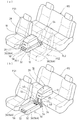
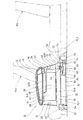
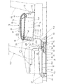
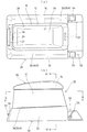
図1は、好適実施例に係るコンソールボックスの使用状態を例示した説明斜視図であって、(a)は前部座席間のフロアに設置した第1位置での使用状態を示し、(b)は後部座席の座面上に保持した第2位置での使用状態を示している。また図2は、前部座席間のフロアに設置した第1位置での使用状態で示したコンソールボックスの概略断面図であり、図3は、後部座席の座面上に保持した第2位置での使用状態で示したコンソールボックスの概略断面図である。更に図4(a)は、本実施例のコンソールボックスの外観を概略的に示した平面図であり、図4(b)は、その側面図である。なお本実施例では、横長タイプ(ベンチタイプ)の後部座席を装備した車両に実施した場合を例示し、よって該後部座席の座面上における左右中央部が第2位置に設定されている。   FIG. 1 is an explanatory perspective view illustrating a use state of a console box according to a preferred embodiment, wherein (a) shows a use state at a first position installed on a floor between front seats; These show the use state in the 2nd position hold | maintained on the seat surface of the rear seat. FIG. 2 is a schematic cross-sectional view of the console box shown in use in the first position installed on the floor between the front seats, and FIG. 3 is a second position held on the seat surface of the rear seats. It is a schematic sectional drawing of the console box shown by the use condition. Further, FIG. 4A is a plan view schematically showing the appearance of the console box of the present embodiment, and FIG. 4B is a side view thereof. In this embodiment, the case where the vehicle is equipped with a horizontally long type (bench type) rear seat is illustrated, and therefore the left and right central portions on the seating surface of the rear seat are set to the second position.

本実施例のコンソールボックス10は、図1に例示したように、後述のボックス支持機構30に支持された状態で前部座席FS1,FS2間のフロアFL1へ設置され、常にはこのボックス支持機構30に支持されたもとで、前部座席FS1,FS2側の第1位置および後部座席RS側の第2位置との間を移動し得るようになっている。すなわちコンソールボックス10は、図2および図3に例示したように、一端が前部座席FS1,FS2の間のフロアFL1側に枢支されると共に、他端が該コンソールボックス10に枢着される前述のボックス支持機構30を構成する支持部材34で支持され、この支持部材34の姿勢変位(回動変位)のもとに、前部座席FS1,FS2側の第1位置と後部座席RS側の第2位置との間をスウィング移動し得るよう構成されている。これにより、コンソールボックス10を第2位置へ変位させることで、フロアFL1,FL2を介して乗員が前部座席FS1,FS2と後部座席RSとの間を移動(ウォークスルー)し得るようにすると共に、後部座席RSの両側に着座している乗員が当該コンソールボックス10を使用し得るように構成したものである。   As illustrated in FIG. 1, the console box 10 of this embodiment is installed on the floor FL1 between the front seats FS1 and FS2 while being supported by a box support mechanism 30 described later. It is possible to move between the first position on the front seat FS1, FS2 side and the second position on the rear seat RS side. That is, as illustrated in FIGS. 2 and 3, one end of the console box 10 is pivotally supported on the floor FL1 side between the front seats FS1 and FS2, and the other end is pivotally attached to the console box 10. It is supported by the support member 34 that constitutes the box support mechanism 30 described above, and the first position on the front seats FS1 and FS2 side and the rear seat RS side on the basis of the attitude displacement (rotation displacement) of the support member 34 It is configured to be able to swing between the second position. Thus, by displacing the console box 10 to the second position, the occupant can move (walk through) between the front seats FS1, FS2 and the rear seat RS via the floors FL1, FL2. The occupant seated on both sides of the rear seat RS can use the console box 10.

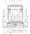
ここで、前述したコンソールボックス10は、図4〜図6に例示するように、例えばポリプロピレン(PP)等の合成樹脂素材からインジェクション成形されたコンソール本体12と、同じくポリプロピレン等の合成樹脂素材から有底矩形状に成形され、コンソール本体12に対して上方から嵌合装着される収容箱体14と、コンソール本体12の上部後方にヒンジ部材18を介して枢支され、収容箱体14により画成された収容部14Aを開放可能に閉成するコンソールリッド16とから基本的に構成されている。コンソール本体12は、その前面および後面に指先を掛けるための取手部20,22が形成されている一方、必要に応じて外面の全体または部分的に、シボ模様を形成したり別途の表皮材を貼込んで質感向上が図られることもある。またコンソールリッド16は、その上面に発泡体24および表皮材26が配設されていて、アームレスト28として機能するようになっている。なおコンソールボックス10自体は、従来のものと大きな差異はないため、詳細な説明は省略する。   Here, as illustrated in FIGS. 4 to 6, the console box 10 described above includes, for example, a console body 12 that is injection-molded from a synthetic resin material such as polypropylene (PP), and a synthetic resin material such as polypropylene. A storage box 14 that is molded into a bottom rectangular shape and is fitted and mounted on the console main body 12 from above, and is pivotally supported via a hinge member 18 at the upper rear of the console main body 12, and is defined by the storage box 14. The console lid 16 is configured basically so as to be able to open the housing portion 14A. The console body 12 is formed with handle portions 20 and 22 for placing fingertips on the front and rear surfaces of the console main body 12, while forming a texture pattern or a separate skin material on the whole or a part of the outer surface as required. The texture may be improved by pasting. The console lid 16 is provided with a foam 24 and a skin material 26 on its upper surface, and functions as an armrest 28. Since the console box 10 itself is not significantly different from the conventional one, detailed description thereof is omitted.

ボックス支持機構30は、前部座席FS1,FS2の間のフロアFL1に設置された支持台32と、この支持台32に枢支された前述の支持部材34とから構成されている。支持台32は、その平面視での形状・サイズがコンソールボックス10のコンソール本体12より一回り大きく設定された逆バケット形状を呈しており、その上面における左右両側に、第1位置へ到来した当該のコンソールボックス10を当て受ける載置面36Aを形成した載置部36,36が突設されている。そして、支持台32の後部には後述するロック機構50が配設されていると共に、当該支持台32の後部および前部には後述する操作部材54,56が配設されている。   The box support mechanism 30 includes a support base 32 installed on the floor FL1 between the front seats FS1 and FS2, and the above-described support member 34 pivotally supported by the support base 32. The support base 32 has an inverted bucket shape in which the shape and size in plan view is set to be slightly larger than the console body 12 of the console box 10, and the support base 32 arrives at the first position on both the left and right sides of the upper surface. The mounting portions 36 and 36 having a mounting surface 36A for receiving the console box 10 are projected. A lock mechanism 50 described later is disposed at the rear portion of the support base 32, and operation members 54 and 56 described later are disposed at the rear portion and the front portion of the support base 32.

支持部材34は、図5および図6等に例示したように、第1支持杆部40Aおよび第2支持杆部40Bが略直角に連設された側面略L字形を呈する2本の支持体40,40と、これら支持体40,40を所要幅に連結する連結杆42,42とから構成されている。そして、各々の支持体40,40の一端、すなわち第1支持杆部40Aの端部が、第1ヒンジ部材44を利用して前述の支持台32の上面に枢着されており、これにより支持部材34は、乗員室の前後方向(図2における左右方向)への回動が可能となっている。また、各々の支持体40,40の他端、すなわち第2支持杆部40Bの端部が、第2ヒンジ部材46を利用してコンソール本体12における天面裏側に枢支されている。なお、コンソール本体12と収容箱体14との間には所要幅の空間48が画成されており、各支持体40,40の第2支持杆部40Bが、この空間48を介して対応の第2ヒンジ部材46,46へ臨むようになる。   As illustrated in FIGS. 5 and 6 and the like, the support member 34 includes two support bodies 40 having a substantially L-shaped side surface in which a first support collar part 40A and a second support collar part 40B are connected substantially at right angles. , 40 and connecting rods 42, 42 for connecting these supports 40, 40 to the required width. One end of each support body 40, that is, the end portion of the first support collar 40A is pivotally attached to the upper surface of the support base 32 using the first hinge member 44. The member 34 can be rotated in the front-rear direction (left-right direction in FIG. 2) of the passenger compartment. Further, the other end of each support 40, 40, that is, the end of the second support collar 40 </ b> B is pivotally supported on the back side of the console main body 12 using the second hinge member 46. A space 48 having a required width is defined between the console main body 12 and the housing box 14, and the second support flanges 40 </ b> B of the respective support bodies 40 and 40 correspond to each other via the space 48. The second hinge members 46 and 46 are faced.

また、前述した各々の第2ヒンジ部材46,46は、コンソール本体12の天面裏側において該コンソール本体12の前後方向へ延在するよう配設した所要長のレール部材38,38にスライド可能に配設されている。従ってコンソールボックス10は、前述した支持部材34に対して回動変位およびスライド変位が可能となっており、この支持部材34の姿勢変位に伴って前述した第1位置および第2位置の間でのスウィング変位が可能となっている。なお図2および図3に例示したように、コンソールボックス10が支持台32の載置面36A,36Aに保持されて第1位置に到来している場合の支持部材34の姿勢は、第1支持杆部40Aが略垂直状態で第2支持杆部40Bが略水平状態となっており、また当該のコンソールボックス10が後部座席RSの座面上に保持された第2位置に到来している場合の支持部材34の姿勢は、第1支持杆部40Aが略水平状態で第2支持杆部40Bが略垂直状態となっており、該支持部材34は約90度回動するようになる。   Each of the second hinge members 46, 46 described above is slidable on a rail member 38, 38 of a required length disposed so as to extend in the front-rear direction of the console body 12 on the back side of the top surface of the console body 12. It is arranged. Accordingly, the console box 10 can be rotated and slid relative to the support member 34 described above, and the position of the support member 34 is changed between the first position and the second position described above. Swing displacement is possible. As illustrated in FIGS. 2 and 3, the attitude of the support member 34 when the console box 10 is held by the mounting surfaces 36 </ b> A and 36 </ b> A of the support base 32 and arrives at the first position is the first support. When the collar portion 40A is substantially vertical and the second support collar portion 40B is substantially horizontal, and the console box 10 has arrived at the second position held on the seat surface of the rear seat RS. The posture of the support member 34 is such that the first support collar portion 40A is substantially horizontal and the second support collar portion 40B is substantially vertical, and the support member 34 rotates about 90 degrees.

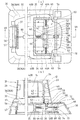
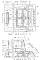
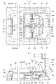
前述したロック機構50は、第1位置および第2位置に到来したコンソールボックス10を、支持部材34の回動変位を規制することで固定保持させるためのものであって、図6および図7に例示するように、コンソールボックス10が第1位置または第2位置に停止した夫々の状態において、支持部材34における各支持体40,40の第1支持杆部40Aへ係合する一対の規制部材52,52と、支持台32の所要位置に配設されて各規制部材52,52に連繋され、所要の操作により各支持体40,40に対する該規制部材52,52の係合を解除する操作部材54,56とから構成されている。ここで、一方の操作部材54は、後部座席RS側からの操作が可能なように支持台32の後側に配設されたペダル形態の操作ペダルであり、他方の操作部材56は、前部座席FS1,FS2側からの操作が可能なように支持台32の前側に配設されたレバー形態の操作レバーである。これによりコンソールボックス10は、第1位置または第2位置に到来すると、支持部材34に係合した規制部材52,52により安定的に固定保持されると共に、操作ペダル54または操作レバー56を操作して支持部材34に対する規制部材52,52の係合を解除することで、第1位置から第2位置への変位および第2位置から第1位置への変位が許容される。   The lock mechanism 50 described above is for fixing and holding the console box 10 that has arrived at the first position and the second position by restricting the rotational displacement of the support member 34, and is shown in FIGS. As illustrated, in a state where the console box 10 is stopped at the first position or the second position, the pair of regulating members 52 that engage with the first support flanges 40A of the support bodies 40, 40 in the support member 34. , 52 and an operation member which is disposed at a required position of the support base 32 and is connected to the respective restriction members 52, 52, and releases the engagement of the restriction members 52, 52 with respect to the respective support bodies 40, 40 by a required operation. 54, 56. Here, one operation member 54 is a pedal-type operation pedal disposed on the rear side of the support base 32 so that an operation from the rear seat RS side is possible, and the other operation member 56 is a front portion. It is an operation lever in the form of a lever arranged on the front side of the support base 32 so that the operation from the seat FS1, FS2 side is possible. As a result, when the console box 10 arrives at the first position or the second position, the console box 10 is stably fixed and held by the restriction members 52 and 52 engaged with the support member 34, and the operation pedal 54 or the operation lever 56 is operated. By releasing the engagement of the restriction members 52 and 52 with respect to the support member 34, displacement from the first position to the second position and displacement from the second position to the first position are allowed.

各々の規制部材52は、支持台32に形成した案内孔33,33に沿って該支持台32の幅方向(図6の左右方向)へスライド可能に支持された作動部材58,58に取着され、これら作動部材58,58の移動に伴って支持部材34の支持体40,40に対する係脱が図られるようになっている。各作動部材58は、案内孔33,33を挿通して支持台32の上面へ延出し前述の規制部材52を支持する本体部58Aと、本体部58Aの端縁部に延設されて後述のスライド部材62に係止される係止部58Bとを有しており、支持台32の内部に形成された支持壁35の壁面に連結されたコイルスプリング60,60に連結されている。これにより、常には相互に離間する方向へ引張り付勢され、支持部材34における各支持体40,40の第1支持杆部40Aに規制部材52を係合した状態に保持される(図6、図7)。   Each regulating member 52 is attached to operating members 58 and 58 supported so as to be slidable in the width direction of the support base 32 (left and right direction in FIG. 6) along guide holes 33 and 33 formed in the support base 32. As the operation members 58 and 58 are moved, the support member 34 is engaged with and disengaged from the support bodies 40 and 40. Each actuating member 58 is inserted into the guide holes 33, 33 and extends to the upper surface of the support base 32. The main body portion 58A supports the restriction member 52 described above, and extends to the edge of the main body portion 58A. It has a locking portion 58B that is locked to the slide member 62, and is connected to coil springs 60, 60 connected to the wall surface of the support wall 35 formed inside the support base 32. As a result, they are always pulled and biased in directions away from each other, and are held in a state in which the restricting member 52 is engaged with the first support flanges 40A of the supports 40, 40 in the support member 34 (FIG. 6, FIG. 6). Fig. 7).

台形枠形状を呈するスライド部材62は、図7(a),(b)に例示したように、各図の左側が幅狭、右側が幅広となる向きで支持台32の内側に配設されて、前述した支持壁35の壁面に連結されたコイルスプリング64に連結されており、常には図7(a)の左方向へ引張り付勢されている。そして、スライド部材62がコイルスプリング64の引張り付勢により図7(a),(b)に図示した第1停止位置に停止した状態において、前述した各作動部材58,58の係止部58Bが、当該スライド部材62の最大幅部に係止するようになっている。また、スライド部材62が前述した第1停止位置から図の右方向へ移動すると、係止部58Bが該スライド部材62の傾斜部に沿って摺動することで各作動部材58,58は相互に近接する方向へスライド移動するようになり、図8(a),(b)に図示した第2停止位置まで移動した際には係止部58Bが該スライド部材62の最小幅部に到来するので、支持部材34における各支持体40,40の第1支持杆部40Aに対する規制部材52の係合が解除された状態となる。   As illustrated in FIGS. 7A and 7B, the slide member 62 having a trapezoidal frame shape is disposed inside the support base 32 in such a direction that the left side of each figure is narrow and the right side is wide. The coil spring 64 is connected to the wall surface of the support wall 35 described above, and is always urged to the left in FIG. When the slide member 62 is stopped at the first stop position illustrated in FIGS. 7A and 7B by the tension bias of the coil spring 64, the locking portions 58B of the operation members 58 and 58 described above are The slide member 62 is locked to the maximum width portion. Further, when the slide member 62 moves from the first stop position described above to the right in the drawing, the locking portion 58B slides along the inclined portion of the slide member 62, so that the respective operation members 58, 58 are mutually connected. Since the sliding portion 62B comes to slide in the approaching direction and moves to the second stop position shown in FIGS. 8A and 8B, the locking portion 58B arrives at the minimum width portion of the sliding member 62. Then, the engagement of the regulating member 52 to the first support collar portion 40A of each support body 40, 40 in the support member 34 is released.

前述した操作ペダル54は、支持台32の後部において幅方向へ延在するよう配設された回動支軸70の両端に取着されており、この回動支軸70に設けた第1係止片72が前述したスライド部材62に連設された係止片部66に設けた係止孔68へ係合していることで、これら回動支軸70、スライド部材62および作動部材58,58を介して前述した各規制部材52,52に連繋している。そして、前述したスプリング64の引張り付勢力により、スライド部材62が第1停止位置に停止している際には、図7(a),(b)に例示したように、各々の操作ペダル54,54は略起立姿勢に保持されている。従って、左右何れかの操作ペダル54を足等で上方から押圧すると、図8(a),(b)に例示したように、回動支軸70が図の時計方向へ回動すると共に、これに連動してスライド部材62が第2停止位置へ変位するようになるため、前述したように各作動部材58,58が相互に近接するようスライド移動して、支持部材34に対する規制部材52,52の係合が解除されるようになる。   The operation pedal 54 described above is attached to both ends of a rotation support shaft 70 disposed so as to extend in the width direction at the rear portion of the support base 32, and a first engagement provided on the rotation support shaft 70. The stop piece 72 is engaged with a locking hole 68 provided in the locking piece portion 66 connected to the slide member 62 described above, so that the rotation support shaft 70, the slide member 62, and the operating member 58, It is connected to the above-described regulating members 52 and 52 through 58. When the slide member 62 is stopped at the first stop position by the tension biasing force of the spring 64 described above, as illustrated in FIGS. 7A and 7B, the operation pedals 54, 54 is held in a substantially upright posture. Therefore, when one of the left and right operation pedals 54 is pressed from above with a foot or the like, as illustrated in FIGS. 8 (a) and 8 (b), the rotation support shaft 70 rotates in the clockwise direction in the figure. Since the slide member 62 is displaced to the second stop position in conjunction with this, the operation members 58 and 58 are slid so as to be close to each other as described above, and the restriction members 52 and 52 with respect to the support member 34 are moved. Is disengaged.

前述した操作レバー56は、支持台32の前部において該支持台32の設置部37へ回動可能に取付けられており、この操作レバー56に連繋された長尺の連結杆80に設けた係止孔82へ前述した回動支軸70に設けた第2係止片74が係合していることで、これら連結杆80、回動支軸70、スライド部材62および作動部材58,58を介して前述した各規制部材52,52に連繋している。そして、前述したスプリング64の引張り付勢力により、スライド部材62が第1停止位置に停止している際には、図7(a),(b)に例示したように、操作レバー56は指先掛止部57が略水平となった姿勢に保持されている。従って、操作レバー56の指先掛止部57を指先等で上方へ引き上げると、図11(a),(b)に例示するように、連結杆80が移動して回動支軸70が図の時計方向へ回転すると共に、これに連動してスライド部材62が第2停止位置へ変位するようになるため、前述したように各作動部材58,58が相互に近接するようスライド移動して、支持部材34に対する規制部材52,52の係合が解除されるようになる。   The operation lever 56 described above is rotatably attached to the installation portion 37 of the support base 32 at the front portion of the support base 32, and the engagement lever provided on a long connecting rod 80 connected to the operation lever 56. Since the second locking piece 74 provided on the rotation support shaft 70 is engaged with the stop hole 82, the connecting rod 80, the rotation support shaft 70, the slide member 62, and the operation members 58 and 58 are connected. Via the control members 52 and 52 described above. Then, when the slide member 62 is stopped at the first stop position by the tension biasing force of the spring 64 described above, as illustrated in FIGS. 7A and 7B, the operation lever 56 is engaged with the fingertip. The stop portion 57 is held in a substantially horizontal posture. Therefore, when the fingertip latching portion 57 of the operation lever 56 is pulled upward with a fingertip or the like, the connecting rod 80 is moved and the rotation support shaft 70 is moved as shown in FIGS. 11 (a) and 11 (b). As the slide member 62 rotates in the clockwise direction and the slide member 62 is displaced to the second stop position in conjunction with the rotation, the operation members 58 and 58 are slid and supported so as to be close to each other as described above. The engagement of the restricting members 52 and 52 with respect to the member 34 is released.

なお本実施例に例示の構造では、操作レバー56を指先等で操作した場合には、各操作ペダル54,54も連動して揺動するようになっている(回動支軸70が回動するため)。また、操作レバー56と連結杆80とは一方向にのみ係止されるようになっており、操作ペダル54を足等で操作した場合には、該操作レバー56は揺動しないようになっている。但し、ロック機構50の構造を変更することで、操作レバー56と操作ペダル54,54とを、連動するようにしたり或いは非連動とすることも可能である。   In the structure illustrated in this embodiment, when the operation lever 56 is operated with a fingertip or the like, the operation pedals 54 and 54 are also rocked in conjunction with each other (the rotation support shaft 70 is rotated). To do). Further, the operation lever 56 and the connecting rod 80 are locked only in one direction. When the operation pedal 54 is operated with a foot or the like, the operation lever 56 does not swing. Yes. However, by changing the structure of the lock mechanism 50, the operation lever 56 and the operation pedals 54 and 54 can be interlocked or not interlocked.

(実施例の作用)
次に、前述のように構成された本実施例のコンソールボックスの作用について説明する。
(Operation of Example)
Next, the operation of the console box of the present embodiment configured as described above will be described.

本実施例のコンソールボックス10は、図1(a)、図2および図4に例示したように、通常の使用時には、支持台32の載置部36,36に載置された第1位置に保持させ、前述したロック機構50の規制部材52,52によりスウィング変位が規制された状態で実施に供される。この場合には、前部座席FS1,FS2の間のフロアFL1に位置しているため、これら前部座席FS1,FS2に着座した乗員が好適に使用し得る。すなわち、コンソールリッド16を開閉することで、内部に画成された収容部14Aに対する身辺の小間物等の出し入れをすることができる一方、このコンソールリッド16に設けたアームレスト28も好適に使用することができる。   As illustrated in FIGS. 1A, 2, and 4, the console box 10 of the present embodiment is placed at the first position placed on the placement portions 36 and 36 of the support base 32 during normal use. The swinging displacement is restricted by the restricting members 52 and 52 of the lock mechanism 50 described above, and is put into practice. In this case, since the vehicle is located on the floor FL1 between the front seats FS1 and FS2, passengers seated on the front seats FS1 and FS2 can be preferably used. That is, by opening and closing the console lid 16, it is possible to put in and take out personal belongings etc. with respect to the accommodating portion 14 </ b> A defined inside, while the armrest 28 provided on the console lid 16 can also be preferably used. it can.

後部座席RSの乗員が前部座席FS1,FS2へ移動する必要が生じた場合には、先ず図8(a),(b)に例示したように、左右何れかの操作ペダル54を足で踏んで支持部材34に対する規制部材52,52の係合を解除させたもとで、前述した取手部22を利用してコンソールボックス10を全体的に引き上げる。これによりコンソールボックス10は、図3および図9(a),(b)に例示するように、回動が許容された支持部材34の回動変位に伴って後部座席RSの側へスウィング変位するようになる。更に、後部座席RSの座面上近くまで変位したコンソールボックス10を更に後方側へ引張ることで、該コンソールボックス10は後方へスライド移動するようになり、該後部座席RSの座面上に載置されて第2位置で停止するに至る。これにより、前部座席FS1,FS2の間のフロアFL1および後部座席RS前のフロアFL2が連通状態となり、後部座席RSの乗員が前部座席FS1,FS2へ移動可能となる。なお、コンソールボックス10の移動完了後に操作ペダル54から足を離すと、図10(a),(b)に例示するように、該操作ペダル54は元の状態に回動復帰すると共に、支持部材34に対して規制部材52が係合した状態となり、該コンソールボックス10は第2位置に固定保持される。   When a passenger in the rear seat RS needs to move to the front seats FS1 and FS2, first, as illustrated in FIGS. 8A and 8B, first step on the left or right operation pedal 54 with his / her foot. The console box 10 is pulled up as a whole using the handle portion 22 described above while the engagement of the regulating members 52 and 52 with respect to the support member 34 is released. As a result, as illustrated in FIGS. 3 and 9A and 9B, the console box 10 is swung to the rear seat RS side in accordance with the rotational displacement of the support member 34 that is permitted to rotate. It becomes like this. Further, by pulling the console box 10 that has been displaced to near the seat surface of the rear seat RS further rearward, the console box 10 slides backward and is placed on the seat surface of the rear seat RS. To stop at the second position. As a result, the floor FL1 between the front seats FS1 and FS2 and the floor FL2 in front of the rear seat RS are in communication with each other, and a passenger in the rear seat RS can move to the front seats FS1 and FS2. When the foot is released from the operation pedal 54 after the movement of the console box 10 is completed, the operation pedal 54 returns to its original state as illustrated in FIGS. 10A and 10B, and the support member 34, the restricting member 52 is engaged, and the console box 10 is fixedly held at the second position.

一方、前部座席FS1,FS2の乗員が後部座席RSへ移動する必要が生じた場合には、先ず図11(a),(b)に例示するように、操作レバー56を片方の手で上方へ引き上げて支持部材34に対する規制部材52,52の係合を解除させたもとで、前述した取手部20を利用してコンソールボックス10を全体的に引き上げる。これによりコンソールボックス10は、図3および図9(a),(b)に例示したように、回動が許容された支持部材34の回動変位に伴って後部座席RSの側へスウィング変位するようになる。更に、後部座席RSの座面上近くまで変位したコンソールボックス10を更に後方側へ押すことで、該コンソールボックス10は後方へスライド移動するようになり、該後部座席RSの座面上に載置されて第2位置で停止するに至る。これにより、前部座席FS1,FS2の間のフロアFL1および後部座席RSのフロアFL2が連通状態となり、前部座席FS1,FS2の乗員が後部座席RSへ移動可能となる。なお、コンソールボックス10の移動完了後に操作レバー56から手を離すと、該操作レバー56は元の状態に回動復帰すると共に、支持部材34に対して規制部材52が係合した状態となり、該コンソールボックス10は第2位置に固定保持される。   On the other hand, when the occupants of the front seats FS1 and FS2 need to move to the rear seat RS, first, as illustrated in FIGS. 11A and 11B, the operation lever 56 is moved upward with one hand. The console box 10 is pulled up as a whole by using the handle portion 20 described above while releasing the engagement of the restricting members 52 and 52 with respect to the support member 34 by pulling up. As a result, as illustrated in FIGS. 3 and 9A and 9B, the console box 10 is swung to the rear seat RS side with the rotational displacement of the support member 34 that is permitted to rotate. It becomes like this. Further, by pushing the console box 10 that has been displaced to near the seat surface of the rear seat RS further rearward, the console box 10 slides backward and is placed on the seat surface of the rear seat RS. To stop at the second position. As a result, the floor FL1 between the front seats FS1 and FS2 and the floor FL2 of the rear seat RS are in communication with each other, and passengers in the front seats FS1 and FS2 can move to the rear seat RS. If the hand is released from the operation lever 56 after the movement of the console box 10 is completed, the operation lever 56 returns to its original state and the regulating member 52 is engaged with the support member 34, The console box 10 is fixedly held at the second position.

そして本実施例のコンソールボックス10は、前述した支持台32を設けたことによりコンソール本体12の高さ寸法が小さく設定されているため、図3から明らかなように、第1位置での高さレベルと第2位置での高さレベルに大きな差が生じないようになっている。従って、第2位置に固定保持されている場合には、横長の後部座席RSにおける座面の左右中央に位置しているため、この後部座席RSの両側に着座した何れの乗員も好適に使用し得る。すなわち後部座席RSの乗員は、コンソールリッド16を開閉することで、内部に画成された収容部14Aに対する身辺の小間物等の出し入れをすることができる一方、このコンソールリッド16に設けたアームレスト28も好適に使用することができる。   In the console box 10 of the present embodiment, since the height of the console body 12 is set small by providing the support base 32 described above, the height at the first position is clear from FIG. There is no significant difference between the level and the height level at the second position. Therefore, when it is fixedly held at the second position, it is located at the center of the left and right of the seat surface of the horizontally long rear seat RS, so any passenger seated on both sides of the rear seat RS is preferably used. obtain. That is, the occupant of the rear seat RS can open and close the console lid 16 to put in and take out personal belongings and the like with respect to the accommodating portion 14A defined therein, while the armrest 28 provided on the console lid 16 is also provided. It can be preferably used.

後部座席RSの乗員が第2位置に固定保持されているコンソールボックス10を第1位置へ移動させる場合は、先ず取手部20を利用してコンソールボックス10を前側へ引張って移動させる。次いで、操作ペダル54を足で踏んで支持部材34に対する各規制部材52,52の係合を解除し、このもとで取手部22を利用してコンソールボックス10を更に前側へ移動させる。これによりコンソールボックス10は、回動が許容された支持部材34の回動変位に伴って前部座席FS1,FS2の間へスウィング変位して、支持台32の載置面36Aに載置された第1位置へ変位するようになる。そして、コンソールボックス10が支持台32に載置されたら、操作ペダル54から足を離すことで該操作ペダル54は元の状態に回動復帰すると共に、支持部材34に対して各規制部材52,52が係合した状態となり、コンソールボックス10は第1位置に固定保持される。   When the occupant of the rear seat RS moves the console box 10 fixedly held at the second position to the first position, the console box 10 is first pulled and moved using the handle portion 20. Next, the operation pedal 54 is stepped on with the foot to release the engagement of the restricting members 52 and 52 with respect to the support member 34, and the console box 10 is further moved forward using the handle portion 22. As a result, the console box 10 is swung between the front seats FS1 and FS2 along with the rotational displacement of the support member 34 that is allowed to rotate, and is placed on the placement surface 36A of the support base 32. It will be displaced to the first position. When the console box 10 is placed on the support base 32, the operation pedal 54 is returned to its original state by releasing the foot from the operation pedal 54, and the restricting members 52, 52 is engaged, and the console box 10 is fixedly held at the first position.

また、前部座席FS1,FS2の乗員が第2位置に固定保持されているコンソールボックス10を第1位置へ移動させる場合は、先ず取手部20を利用して一方の手でコンソールボックス10を手前側へ引張って移動させる。次いで、操作レバー56を他方の手で上方へ引き上げて支持部材34に対する各規制部材52,52の係合を解除し、このもとでコンソールボックス10を更に手前側へ引張る。これによりコンソールボックス10は、回動が許容された支持部材34の回動変位に伴って前部座席FS1,FS2の間へスウィング変位して、支持台32の載置面36Aに載置された第1位置へ変位するようになる。そして、コンソールボックス10が支持台32に載置されたら、操作レバー56から手を離すことで該操作レバー56は元の状態に回動復帰すると共に、支持部材34に対して各規制部材52,52が係合した状態となり、コンソールボックス10は第1位置に固定保持される。   When the occupant of the front seats FS1 and FS2 moves the console box 10 fixedly held at the second position to the first position, the console box 10 is first moved forward with one hand using the handle portion 20. Pull and move to the side. Next, the operating lever 56 is lifted upward with the other hand to disengage the restricting members 52, 52 from the support member 34, and the console box 10 is further pulled to the near side. As a result, the console box 10 is swung between the front seats FS1 and FS2 along with the rotational displacement of the support member 34 that is allowed to rotate, and is placed on the placement surface 36A of the support base 32. It will be displaced to the first position. When the console box 10 is placed on the support base 32, the operation lever 56 is returned to its original state by releasing the hand from the operation lever 56, and the restricting members 52, 52 is engaged, and the console box 10 is fixedly held at the first position.

このように本実施例のコンソールボックス10では、後部座席RSの乗員がコンソールボックス10を第2位置へ移動させ得ることは勿論、前部座席FS1,FS2の乗員がコンソールボックス10を第2位置に移動させることも可能であるから、後部座席RSの乗員が前部座席FS1,FS2へウォークスルーしたり、前部座席FS1,FS2の乗員が後部座席RSへウォークスルーすることが可能となる。また、第2位置へ固定保持されたコンソールボックス10は、後部座席RSの座面の左右中央に位置するため、この後部座席RSの左右両側に着座した乗員が好適に使用可能である。しかも、コンソール本体12の高さ寸法が小さく設定されているため、後部座席RSの乗員がコンソールリッド16に設けたアームレスト28を好適に使用することができる。   Thus, in the console box 10 of the present embodiment, the occupant of the rear seat RS can move the console box 10 to the second position, and the occupants of the front seats FS1 and FS2 bring the console box 10 to the second position. Since it is also possible to move, the occupant of the rear seat RS can walk through to the front seats FS1, FS2, and the occupant of the front seat FS1, FS2 can walk through to the rear seat RS. Further, since the console box 10 fixedly held at the second position is located at the left and right center of the seat surface of the rear seat RS, an occupant seated on both the left and right sides of the rear seat RS can be suitably used. And since the height dimension of the console main body 12 is set small, the passenger | crew of the rear seat RS can use the armrest 28 provided in the console lid 16 suitably.

また本実施例のコンソールボックス10は、第1位置および第2位置の何れに位置していてもロック機構50により好適な固定保持が図られるため、第1位置に保持されているコンソールボックス10が急発進により後部座席RS側へ移動することが防止される一方、第2位置に保持されている該コンソールボックス10が急ブレーキにより前部座席FS1,FS2側へ移動することも防止される。   Further, the console box 10 of this embodiment can be suitably fixed and held by the lock mechanism 50 regardless of whether the console box 10 is located at the first position or the second position. While moving to the rear seat RS side by sudden start is prevented, the console box 10 held at the second position is also prevented from moving to the front seats FS1, FS2 side by sudden braking.

そして本実施例のコンソールボックス10は、後部座席RSの構造を変更する必要がないため、この後部座席RSの構造変更に伴うコストアップを招来することはない。更に、後部座席RSの両側に乗員が着座していたとしても、コンソールボックス10を第2位置へスウィング変位させ得るため、乗員の有無によってコンソールボックス10の移動が規制されることはない。更にまた、コンソールボックス10を第2位置へ変位させたとしても、前部座席FS1,FS2のリクライニング機能を阻害することはない。   And since the console box 10 of a present Example does not need to change the structure of the rear seat RS, it does not cause the cost increase accompanying the structure change of this rear seat RS. Furthermore, even if an occupant is seated on both sides of the rear seat RS, the console box 10 can be swung to the second position, and therefore the movement of the console box 10 is not restricted by the presence or absence of the occupant. Furthermore, even if the console box 10 is displaced to the second position, the reclining function of the front seats FS1, FS2 is not hindered.

(変更例)
図12は、変更例に係るコンソールボックス10の使用状態を例示した概略斜視図であって、(a)は前部座席間のフロアに設置した第1位置での使用状態を示し、(b)は左右に離間して設置された後部座席の間のフロア上に保持した第2位置での使用状態を示している。すなわちこの変更例では、キャプテンタイプの後部座席RS1,RS2を装備した乗用車に実施した場合を例示し、これら後部座席RS1,RS2の間のフロアFL3上が第2位置に設定されている。この変更例においても、コンソールボックス10は前述した実施例と同一の構成であり、ボックス支持機構30やロック機構50等も基本的には同一に構成されている。但し、ボックス支持機構30における支持部材34の回動(スウィング)角度が、前述した実施例よりも大きい90度以上に設定されており、支持部材34が完全に回動した際には、コンソール本体12の下縁がフロアFL3に接触するようになる。但し、支持部材34の支持強度が充分である場合には、フロアFL3から適宜浮上した位置において固定保持させるようにしてもよい。
(Example of change)
FIG. 12 is a schematic perspective view illustrating the use state of the console box 10 according to the modified example, in which (a) shows the use state at the first position installed on the floor between the front seats, (b) Shows the use state at the second position held on the floor between the rear seats spaced apart from each other on the left and right. That is, in this modified example, the case where it is applied to a passenger car equipped with captain-type rear seats RS1 and RS2 is illustrated, and the floor FL3 between the rear seats RS1 and RS2 is set at the second position. Also in this modified example, the console box 10 has the same configuration as that of the above-described embodiment, and the box support mechanism 30 and the lock mechanism 50 are basically configured in the same manner. However, the rotation (swing) angle of the support member 34 in the box support mechanism 30 is set to 90 degrees or more, which is larger than that of the above-described embodiment, and when the support member 34 is completely rotated, the console body 12 comes into contact with the floor FL3. However, when the support strength of the support member 34 is sufficient, the support member 34 may be fixedly held at a position appropriately levitated from the floor FL3.

このような変更例に係るコンソールボックス10においても、前述した実施例のコンソールボックス10と同等の作用効果が得られる。すなわち、後部座席RS1,RS2の乗員がコンソールボックス10を第2位置へ移動させ得ることは勿論、前部座席FS1,FS2の乗員がコンソールボックス10を第2位置に移動させることも可能であるから、後部座席RS1,RS2の乗員が前部座席FS1,FS2へウォークスルーしたり、前部座席FS1,FS2の乗員が後部座席RS1,RS2へウォークスルーすることも可能となる。また第2位置へ固定保持されたコンソールボックス10は、後部座席RS1,RS2の間に位置するため、これら後部座席RS1,RS2の夫々に着座した乗員が好適に使用可能である。しかも、後部座席RSの乗員がコンソールリッド16に設けたアームレスト28を使用することもできる。またコンソールボックス10は、第1位置および第2位置の何れに位置していてもロック機構50により好適な固定保持が図られるため、当該乗用車の急発進や急ブレーキに際して移動することが防止される。   Also in the console box 10 according to such a modified example, the same effects as the console box 10 of the above-described embodiment can be obtained. That is, since the passengers in the rear seats RS1 and RS2 can move the console box 10 to the second position, the passengers in the front seats FS1 and FS2 can also move the console box 10 to the second position. The passengers in the rear seats RS1 and RS2 can walk through to the front seats FS1 and FS2, and the passengers in the front seats FS1 and FS2 can walk through to the rear seats RS1 and RS2. Moreover, since the console box 10 fixedly held at the second position is located between the rear seats RS1 and RS2, passengers seated in the rear seats RS1 and RS2 can be preferably used. Moreover, the armrest 28 provided on the console lid 16 by the occupant of the rear seat RS can also be used. In addition, the console box 10 is suitably fixed and held by the lock mechanism 50 regardless of whether the console box 10 is located at the first position or the second position, so that the console box 10 is prevented from moving during sudden start or sudden braking of the passenger car. .

なお前述した実施例のコンソールボックス10では、支持部材34に対して回動変位およびスライド変位が可能な場合を例示したが、後部座席RSの設置位置、支持部材34の形状・サイズ等の設定により、スライド移動しないように構成することもできる。   In the console box 10 according to the above-described embodiment, the case where the rotational displacement and the slide displacement are possible with respect to the support member 34 is illustrated. Also, it can be configured not to slide.

また、ボックス支持構造30を構成する支持台34や支持部材34の形状・形態、操作ペダル54や操作レバー56の操作により規制部材52を移動させるロック機構50の構成等は、前述した実施例のものに限定されるものではなく、同様の作用効果が得られる構成であれば適宜に変更し得る。   Further, the shape and form of the support base 34 and the support member 34 constituting the box support structure 30, the configuration of the lock mechanism 50 that moves the regulating member 52 by the operation of the operation pedal 54 and the operation lever 56, etc. However, the present invention is not limited to this, and can be appropriately changed as long as the same function and effect can be obtained.

本発明に係るコンソールボックスは、前部座席および後部座席を有する車両の乗員室内において、常には前部座席の間のフロアに設置されるコンソールボックスであって、前部座席側と後部座席側との間を変位可能としたもので、コンソールボックスを有する全ての自動車に好適に実施可能である。   A console box according to the present invention is a console box that is always installed on a floor between front seats in a passenger compartment of a vehicle having a front seat and a rear seat, and includes a front seat side and a rear seat side. This is suitable for all automobiles having a console box.

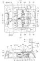
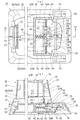
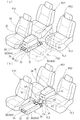
好適実施例に係るコンソールボックスの各使用状態を例示した説明斜視図であって、(a)は前部座席間のフロアに設置した第1位置での使用状態を示し、(b)は後部座席の座面上に保持した第2位置での使用状態を示している。It is explanatory perspective view which illustrated each use condition of the console box concerning a preferred embodiment, (a) shows the use condition in the 1st position installed in the floor between front seats, (b) is a back seat. The use state in the 2nd position hold | maintained on the seat surface of this is shown. 前部座席間のフロアに設置した第1位置での使用状態で示したコンソールボックスの概略断面図である。It is a schematic sectional drawing of the console box shown by the use condition in the 1st position installed in the floor between front seats. 後部座席の座面上に保持した第2位置での使用状態で示したコンソールボックスの概略断面図である。It is a schematic sectional drawing of the console box shown by the use condition in the 2nd position hold | maintained on the seat surface of the rear seat. (a)は、本実施例のコンソールボックスの外観を概略的に示した平面図であり、(b)は、該コンソールボックスの側面図である。(a) is the top view which showed schematically the external appearance of the console box of a present Example, (b) is a side view of this console box. 図4(b)のV−V線断面図である。It is the VV sectional view taken on the line of FIG.4 (b). 図4(b)のVI−VI線断面図である。It is the VI-VI sectional view taken on the line of FIG.4 (b). (a)は、ロック機構の構成を非操作状態で示した説明図であり、(b)は、(a)のVII−VII線断面図である。(a) is explanatory drawing which showed the structure of the locking mechanism in the non-operation state, (b) is the VII-VII sectional view taken on the line of (a). (a)は、操作ペダルを踏むことで支持部材に対する規制部材の係合を解除させた状態を示した説明図であり、(b)は、(a)のVIII−VIII線断面図である。(a) is explanatory drawing which showed the state which released the engagement of the control member with respect to a support member by stepping on an operation pedal, (b) is the VIII-VIII sectional view taken on the line of (a). (a)は、支持部材の回動によりコンソールボックスを第1位置から第2位置へスウィング変位させた状態を示した説明図であり、(b)は、(a)のIX−IX線断面図である。(a) is explanatory drawing which showed the state which carried out the swing displacement of the console box from the 1st position to the 2nd position by rotation of a supporting member, (b) is the IX-IX sectional view taken on the line of (a). It is. (a)は、操作ペダルの踏込みを解除することで支持部材に対して規制部材を係合させた状態を示した説明図であり、(b)は、(a)のX−X線断面図である(a) is explanatory drawing which showed the state which engaged the control member with respect to the support member by cancelling | depressing depression of an operation pedal, (b) is XX sectional drawing of (a). Is (a)は、操作レバーを引き上げることで支持部材に対する規制部材の係合を解除させた状態を示した説明図であり、(b)は、(a)のXI−XI線断面図である。(a) is explanatory drawing which showed the state which released the engagement of the control member with respect to a support member by pulling up an operation lever, (b) is the XI-XI sectional view taken on the line of (a). 変更例に係るコンソールボックスの各使用状態を例示した説明斜視図であって、(a)は前部座席間のフロアに設置した第1位置での使用状態を示し、(b)は後部座席の間のフロア上に保持した第2位置での使用状態を示している。It is explanatory perspective view which illustrated each use condition of the console box which concerns on a modification, Comprising: (a) shows the use condition in the 1st position installed in the floor between front seats, (b) is a rear seat The use state in the 2nd position hold | maintained on the floor between is shown.

符号の説明Explanation of symbols

10 コンソールボックス
16 コンソールリッド
28 アームレスト
30 ボックス支持機構
32 支持台
34 支持部材
50 ロック機構
52 規制部材
54 操作ペダル(操作部材)
56 操作レバー(操作部材)
FL1,FL3 フロア
FS1,FS2 前部座席
RS/RS1,RS2 後部座席
DESCRIPTION OF SYMBOLS 10 Console box 16 Console lid 28 Armrest 30 Box support mechanism 32 Support stand 34 Support member 50 Lock mechanism 52 Control member 54 Operation pedal (operation member)
56 Operation lever (operation member)
FL1, FL3 Floor FS1, FS2 Front seat RS / RS1, RS2 Rear seat

Claims (9)

前部座席(FS1,FS2)および後部座席(RS/RS1,RS2)を有する車両の乗員室内において、常には前記前部座席(FS1,FS2)の間のフロア(FL1)に設置されるコンソールボックス(10)であって、
前記コンソールボックス(10)は、
一端が前記フロア(FL1)側に枢着されると共に、他端が該コンソールボックス(10)に枢支される支持部材(34)で支持され、
前記支持部材(34)の姿勢変位のもとに、前記前部座席(FS1,FS2)側の第1位置と前記後部座席(RS/RS1,RS2)側の第2位置との間を移動し得るよう構成した
ことを特徴とするコンソールボックス。
Console box that is always installed on the floor (FL1) between the front seats (FS1, FS2) in the passenger compartment of a vehicle having front seats (FS1, FS2) and rear seats (RS / RS1, RS2) (10)
The console box (10)
One end is pivotally attached to the floor (FL1) side, and the other end is supported by a support member (34) pivotally supported by the console box (10),
The support member (34) is moved between a first position on the front seat (FS1, FS2) side and a second position on the rear seat (RS / RS1, RS2) side under the displacement of the support member (34). A console box characterized by being configured to obtain.
前記第2位置へ移動したコンソールボックス(10)は、横長に設置された前記後部座席(RS)の座面上に保持される請求項1記載のコンソールボックス。   The console box (10) according to claim 1, wherein the console box (10) moved to the second position is held on a seating surface of the rear seat (RS) installed horizontally. 前記第2位置へ移動したコンソールボックス(10)は、左右に離間して設置された前記後部座席(RS1,RS2)間のフロア(FL3)上に保持される請求項1記載のコンソールボックス。   The console box (10) according to claim 1, wherein the console box (10) moved to the second position is held on a floor (FL3) between the rear seats (RS1, RS2) spaced apart from each other. 前記支持部材(34)は、前記フロア(FL1)に設置されて第1位置に変位した前記コンソールボックス(10)を載置する支持台(32)に枢支され、この支持台(32)と共にボックス支持機構(30)を構成する請求項1〜3の何れかに記載のコンソールボックス。   The support member (34) is pivotally supported by a support base (32) on which the console box (10) placed on the floor (FL1) and displaced to the first position is placed, together with the support base (32). The console box according to any one of claims 1 to 3, constituting a box support mechanism (30). 前記支持台(32)には、前記第1位置および第2位置の夫々に前記コンソールボックス(10)を固定保持するロック機構(50)が配設されている請求項4記載のコンソールボックス。   The console box according to claim 4, wherein the support base (32) is provided with a lock mechanism (50) for fixing and holding the console box (10) at each of the first position and the second position. 前記ロック機構(50)は、前記コンソールボックス(10)が前記第1位置または第2位置に停止した夫々の状態において前記支持部材(34)へ係合する規制部材(52)と、
前記支持台(32)の所要位置に配設されて前記規制部材(52)に連繋し、所要の操作により前記支持部材(34)に対する該規制部材(52)の係合を解除する操作部材(54,56)とからなる請求項5記載のコンソールボックス。
The locking mechanism (50) includes a restricting member (52) that engages with the support member (34) in each state where the console box (10) is stopped at the first position or the second position,
An operation member disposed at a required position of the support base (32) and connected to the restriction member (52) to release the engagement of the restriction member (52) with the support member (34) by a required operation ( 54, 56). The console box according to claim 5.
前記操作部材(54)は、前記支持台(32)において、前記後部座席(RS/RS1,RS2)側からの操作が可能な位置に配設された操作ペダルである請求項6記載のコンソールボックス。   The console box according to claim 6, wherein the operation member (54) is an operation pedal disposed at a position in the support base (32) that can be operated from the rear seat (RS / RS1, RS2) side. . 前記操作部材(56)は、前記支持台(32)において、前記前部座席(FS1,FS2)側からの操作が可能な位置に配設された操作レバーである請求項6または7記載のコンソールボックス。   The console according to claim 6 or 7, wherein the operation member (56) is an operation lever disposed at a position in the support base (32) that can be operated from the front seat (FS1, FS2) side. box. 前記コンソールボックス(10)の上面に、アームレスト(28)を兼用するコンソールリッド(16)が配設されている請求項1〜8の何れかに記載のコンソールボックス。
The console box according to any one of claims 1 to 8, wherein a console lid (16) that also serves as an armrest (28) is disposed on an upper surface of the console box (10).
JP2004118312A 2004-04-13 2004-04-13 Console box Pending JP2005297826A (en)

Priority Applications (1)

Application Number Priority Date Filing Date Title
JP2004118312A JP2005297826A (en) 2004-04-13 2004-04-13 Console box

Applications Claiming Priority (1)

Application Number Priority Date Filing Date Title
JP2004118312A JP2005297826A (en) 2004-04-13 2004-04-13 Console box

Publications (1)

Publication Number Publication Date
JP2005297826A true JP2005297826A (en) 2005-10-27

Family

ID=35329888

Family Applications (1)

Application Number Title Priority Date Filing Date
JP2004118312A Pending JP2005297826A (en) 2004-04-13 2004-04-13 Console box

Country Status (1)

Country Link
JP (1) JP2005297826A (en)

Cited By (3)

* Cited by examiner, † Cited by third party
Publication number Priority date Publication date Assignee Title
DE102007058270A1 (en) * 2007-12-04 2009-06-18 Audi Ag Article i.e. coffee machine, accommodating device for motor vehicle, has housing provided on or between rear seats of vehicle in rear position and provided between front seats of vehicle in front position, by pivoting arrangement
DE102008052734B4 (en) * 2007-10-26 2015-08-06 Toyota Boshoku K.K. Hinterkonsolenbox
WO2020058143A1 (en) * 2018-09-17 2020-03-26 Motherson Innovations Company Ltd. Center console between two vehicle seats and motor vehicle having a center console of this type

Cited By (3)

* Cited by examiner, † Cited by third party
Publication number Priority date Publication date Assignee Title
DE102008052734B4 (en) * 2007-10-26 2015-08-06 Toyota Boshoku K.K. Hinterkonsolenbox
DE102007058270A1 (en) * 2007-12-04 2009-06-18 Audi Ag Article i.e. coffee machine, accommodating device for motor vehicle, has housing provided on or between rear seats of vehicle in rear position and provided between front seats of vehicle in front position, by pivoting arrangement
WO2020058143A1 (en) * 2018-09-17 2020-03-26 Motherson Innovations Company Ltd. Center console between two vehicle seats and motor vehicle having a center console of this type

Similar Documents

Publication Publication Date Title
US7562931B2 (en) Vehicle seat assembly
JP3990364B2 (en) Folding seats and vehicles including such seats
JP4305675B2 (en) Vehicle seat
JP4432674B2 (en) Vehicle seat device
JP5573363B2 (en) Center console device for vehicle
EP1449710A2 (en) Seat device including a stowable auxiliary seat
CN110053525B (en) Vehicle seat
CN105263747A (en) Vehicular seat
JP2005297826A (en) Console box
JP5308191B2 (en) Lid member
JP4551348B2 (en) Armrest
JP5690369B2 (en) Sheet device
JP4331082B2 (en) Vehicle seat structure
JP7819029B2 (en) Vehicle seats
JP5347364B2 (en) Car seat equipment
JP2003246232A (en) Vehicle seat structure
JP7381854B2 (en) vehicle seat
JP3410300B2 (en) Tilt lock mechanism for automotive seat cushion
JP4023425B2 (en) Car
JP2020059353A (en) Vehicular seat
JP6691308B2 (en) Vehicle seat
JPH078060U (en) Vehicle seat structure
JP7385101B2 (en) Vehicle seats and vehicle seat units
JP2000177495A (en) Console Box
JPH07204057A (en) Folding armrest