JP2005297792A - Air-conditioning unit for vehicle - Google Patents
Air-conditioning unit for vehicle Download PDFInfo
- Publication number
- JP2005297792A JP2005297792A JP2004117558A JP2004117558A JP2005297792A JP 2005297792 A JP2005297792 A JP 2005297792A JP 2004117558 A JP2004117558 A JP 2004117558A JP 2004117558 A JP2004117558 A JP 2004117558A JP 2005297792 A JP2005297792 A JP 2005297792A
- Authority
- JP
- Japan
- Prior art keywords
- filter
- air
- vehicle
- intake
- conditioning unit
- Prior art date
- Legal status (The legal status is an assumption and is not a legal conclusion. Google has not performed a legal analysis and makes no representation as to the accuracy of the status listed.)
- Pending
Links
- 238000004378 air conditioning Methods 0.000 title claims abstract description 44
- 230000002093 peripheral effect Effects 0.000 claims abstract description 20
- 238000005192 partition Methods 0.000 claims description 7
- 238000009423 ventilation Methods 0.000 claims description 7
- 238000001816 cooling Methods 0.000 abstract description 15
- 230000015572 biosynthetic process Effects 0.000 abstract 1
- 230000010354 integration Effects 0.000 abstract 1
- 239000002699 waste material Substances 0.000 abstract 1
- 238000007664 blowing Methods 0.000 description 9
- 230000009977 dual effect Effects 0.000 description 8
- 238000010438 heat treatment Methods 0.000 description 6
- 239000000428 dust Substances 0.000 description 3
- 238000012423 maintenance Methods 0.000 description 3
- 230000000694 effects Effects 0.000 description 2
- 238000003780 insertion Methods 0.000 description 2
- 230000037431 insertion Effects 0.000 description 2
- 238000004519 manufacturing process Methods 0.000 description 2
- 235000004347 Perilla Nutrition 0.000 description 1
- 244000124853 Perilla frutescens Species 0.000 description 1
- 238000010586 diagram Methods 0.000 description 1
- XLYOFNOQVPJJNP-UHFFFAOYSA-N water Substances O XLYOFNOQVPJJNP-UHFFFAOYSA-N 0.000 description 1
Images



Landscapes
- Air-Conditioning For Vehicles (AREA)
Abstract
Description
この発明は、例えば車両のセンターコンソール部に搭載される縦置形式の空調ユニットの特にインテークボックスに関するものである。 The present invention relates to, for example, an intake box of a vertically installed air conditioning unit mounted on a center console portion of a vehicle, for example.
車両用空調ユニットを構成するインテークボックスに対し、内外気導入口から侵入する塵芥や水等を排除するために内外気導入口と送風機との間にフィルタを配置することは既に公知である(例えば、特許文献1から5を参照。)。そして、インテ−クボックスのケーシングにフィルタ挿入孔を開口させ、フィルタをこのフィルタ挿入孔から着脱可能とすることも公知である(例えば、特許文献2を参照。)。
It is already known that a filter is disposed between the inside / outside air introduction port and the blower in order to eliminate dust, water, and the like entering from the inside / outside air introduction port with respect to the intake box constituting the vehicle air conditioning unit (for example, , See
また、内外気導入口に対し内外気の導入割合を調節するためのインテークドアとして、円弧状のガイド溝、ラックを有し前記ガイド部に沿って摺動する円弧状のスライドドア、及び前記ラックと噛み合う駆動ギア(ピニオン)を有する駆動軸から構成されるスライドドア装置を用いることも公知である(例えば、特許文献3を参照。)。 In addition, as an intake door for adjusting the introduction ratio of the inside / outside air with respect to the inside / outside air introduction port, an arcuate guide groove, an arcuate slide door having a rack and sliding along the guide part, and the rack It is also known to use a slide door device that includes a drive shaft having a drive gear (pinion) that meshes with the drive gear (see, for example, Patent Document 3).
更に、フィルタを一体の円筒状又は複数の円弧部からなる円筒状に形成し、このフィルタをブロアのケースの空気取入口の周りを囲むように配置することも公知である(例えば、特許文献4を参照。)。 Furthermore, it is also known that the filter is formed into an integral cylindrical shape or a cylindrical shape composed of a plurality of arc portions, and this filter is disposed so as to surround the air inlet of the blower case (for example, Patent Document 4). See).
更にまた、インテークドアとしてスライドドアを採用すると共にフィルタをこのスライドドアの摺動方向に沿った形状として当該スライドドアに並設し、その結果として、スライドとフィルタとの間に不要な空間が生ずるのを防止している構造も公知である(例えは、特許文献5を参照。)。
これに対し、特許文献1及び2のように、内外気導入口と送風機との間に単にフィルタを配置するのみでは、インテークボックスがフィルタ収納容積の確保のために大型化し、近年における車両用空調ユニットの小型化の要請に沿わない。
On the other hand, as in
これを受けて、特許文献3ではインテークドアを、回転軸とドア本体とよりなる形式からスライドドアに変更する着想は示されているが、特許文献3に示す構成では、スライドドアとフィルタとの間に大きな空間が形成されてしまっており、この空間の存在からインテークボックスの小型化には充分に貢献することができない。しかも、この特許文献3は、ブロワユニットとクーリングユニットとが水平方向に連続して配置され、内外気導入口が両方とも上側に開口した車両用空調ユニットを前提としており、近年における送風機の下方にエバポレータが配されるような縦置き形式の一体型の車両用空調ユニットの構造ではそのまま応用させることができない。
In response to this, in
また、特許文献4では、インテークボックス内において、送風機の空気取入口に対し軸方向となる位置にフィルタを配し、このフィルタは空気取入口の周りを囲むように配置したものとする着想は示されているが、これも内外気導入口とフィルタとの間に配置されるドアについて、一方を支点として揺動するドアであるため、その揺動領域を確保するための空間が必要であることから、この空間の存在によりインテークボックスの小型化には充分に貢献することができない。しかも、この特許文献4は、内気導入口と外気導入口とが車両の上下に分かれて開口しているタイプの車両用空調ユニットを前提としており、近年における内気導入口及び外気導入口が車両前方にしかも上下に並列して配置された構成の縦置き形式の一体型の車両用空調ユニットの構造ではそのまま応用させることができない。
Further,
更に、特許文献5では、フィルタと空気取入口との間に大きな空間が形成されてしまっており、この空間の存在からインテークボックスの小型化には充分に貢献することができない。しかも、内気導入口と外気導入口とが車両の真上とやや斜め上方に開口しているタイプの車両用空調ユニットを前提としており、近年における内気導入口及び外気導入口が車両前方を向いて開口し、しかも上下に並列して配置された構成の縦置き形式の一体型の車両用空調ユニットではそのまま応用させることができない。
Further, in
そこで、本発明は、送風機と冷却用熱交換器とが車両上下方向に位置し、内外気導入口が車両進行方向を向いて且つ上下に並設されて開口する縦置き形式一体型の車両用空調ユニットのインテークボックスにフィルタを収納する場合でも、インテークボックス内の空間を削減して、インテークボックスの小型化を図ることを目的とするものである。 Therefore, the present invention is for a vertically installed vehicle in which the blower and the heat exchanger for cooling are positioned in the vertical direction of the vehicle, and the inside / outside air introduction ports face the vehicle traveling direction and are arranged side by side vertically. Even when a filter is housed in an intake box of an air conditioning unit, it is an object to reduce the space in the intake box and reduce the size of the intake box.
本発明に係る車両用空調ユニットは、モータとファンとから成る送風機を少なくともケーシングに収納して構成されたユニット本体を有し、前記ユニット本体は、前記送風機に対しモータの軸方向の外側にインテークボックスを有し、このインテークボックスにスライドドア及びフィルタが収納されていると共に、前記インテークボックスは、外気導入口と内気導入口とが、前記外気導入口が前記内気導入口に対し車両上方に配置されるように、車両進行方向の前方側に開口しており、前記スライドドアは、車両上下方向に沿って移動することで前記外気導入口及び内気導入口の開度割合を調節し、前記フィルタは、前記ケーシングに形成された空気取入口の周縁に対しその軸方向から見て近接していると共に前記スライドドアに沿って配置されていることを特徴としている(請求項1)。尚、前記ユニット本体内には前記送風機に対し車両の下側に冷却用熱交換器が配置されている。 An air conditioning unit for a vehicle according to the present invention has a unit main body configured by housing a blower including a motor and a fan in at least a casing, and the unit main body has an intake outside the axial direction of the motor with respect to the blower. The intake box contains a slide door and a filter, and the intake box has an outside air introduction port and an inside air introduction port, and the outside air introduction port is disposed above the vehicle with respect to the inside air introduction port. As described above, the opening is made forward in the vehicle traveling direction, and the sliding door adjusts the opening ratio of the outside air introduction port and the inside air introduction port by moving along the vehicle vertical direction, and the filter Is located close to the peripheral edge of the air inlet formed in the casing as viewed from the axial direction and along the sliding door It is characterized by being (claim 1). In the unit body, a cooling heat exchanger is disposed below the vehicle with respect to the blower.
本発明に係る車両用空調ユニットは、送風機としてデュアルファンを用いたタイプにあっては、1つのモータと2つのファンとから成る送風機を少なくともケーシングに収納して構成されたユニット本体部を有し、前記ユニット本体は、前記送風機に対しモータの軸方向の両外側に各々インテークボックスを有し、各インテークボックスにスライドドア及びフィルタが収納されていると共に、各インテークボックスは、外気導入口と内気導入口とが、前記外気導入口が前記内気導入口に対し車両上方に配置されるように、車両進行方向の前方側に開口しており、前記スライドドアは、車両上下方向に沿って移動することで前記外気導入口及び内気導入口の開度割合を調節し、前記フィルタは、前記ケーシングに形成された空気取入口の周縁に対しその軸方向から見て近接していると共に前記内外気導入口との間に前記スライドドアに沿って配置されていることを特徴としている(請求項2)。尚、前記ユニット本体内には前記送風機に対し車両の下側に冷却用熱交換器が配置されている。 The vehicle air-conditioning unit according to the present invention has a unit main body configured by housing at least a blower including one motor and two fans in a type using a dual fan as a blower. The unit main body has intake boxes on both outer sides in the axial direction of the motor with respect to the blower. Each intake box houses a slide door and a filter, and each intake box has an outside air inlet and an inside air. The introduction port opens to the front side in the vehicle traveling direction so that the outside air introduction port is arranged above the vehicle with respect to the inside air introduction port, and the slide door moves along the vehicle vertical direction. Thus, the opening ratio of the outside air inlet and the inside air inlet is adjusted, and the filter is disposed at the periphery of the air intake formed in the casing. It is characterized in being arranged along said sliding door between the inner air introduction port with are close when viewed from the axial direction of perilla (Claim 2). In the unit body, a cooling heat exchanger is disposed below the vehicle with respect to the blower.
双方の車両用空調ユニットにおいて、前記スライドドアは、その長手方向に沿った形状が曲板状であってもよい(請求項3)。この場合、前記フィルタは、前記ケーシングに形成された空気取入口に対し前記モータの軸方向に沿った位置に配置され、前記空気取入口の全周を囲むと共に前記スライドドアと同方向に膨らむ円筒状の外形状である(請求項4)。また、前記フィルタは、前記ケーシングに形成された空気取入口に対し前記モータの軸方向に沿った位置に配置され、前記空気取入口のうち空気が回り込まない部位を残して囲むと共に前記スライドドアと同方向に膨らむ曲板状の外形状である(請求項5)。 In both vehicle air-conditioning units, the slide door may have a curved plate shape along the longitudinal direction. In this case, the filter is disposed at a position along the axial direction of the motor with respect to the air intake formed in the casing, and surrounds the entire circumference of the air intake and is a cylinder that expands in the same direction as the slide door. It is an outer shape (claim 4). The filter is disposed at a position along the axial direction of the motor with respect to an air intake formed in the casing, and surrounds the air intake leaving a portion where the air does not go around and the slide door. It is a curved plate-like outer shape that swells in the same direction (Claim 5).
これに対し、双方の車両用空調ユニットにおいて、前記スライドドアは、その長手方向に沿った形状が平板状であてもよい(請求項6)。この場合、前記フィルタは、その長手方向に沿った形状が平板状であり、前記スライドドアの通風方向と対峙する面に沿っていると共に前記空気取入口の周縁に対しその軸方向から見て接している(請求項7)。尚、スライドドアを駆動するための駆動軸は、スライドドアに対し開口部に近接して外側に配置されても、当該スライドドアとフィルタとの間に配置されても良いものである。 On the other hand, in both the vehicle air conditioning units, the shape of the slide door along the longitudinal direction may be flat. In this case, the filter has a flat plate shape along the longitudinal direction, is along a surface facing the ventilation direction of the slide door, and is in contact with the peripheral edge of the air intake port when viewed from the axial direction. (Claim 7). Note that the drive shaft for driving the slide door may be disposed outside the slide door in the vicinity of the opening, or may be disposed between the slide door and the filter.
一方、デュアルファンを用いない車両用空調ユニットにおいて、前記ケーシングに対し、前記送風機とは反対側の面に前記フィルタの着脱可能な開口部が設けられているようにしてもよい(請求項8)。 On the other hand, in a vehicle air-conditioning unit that does not use a dual fan, a detachable opening of the filter may be provided on the surface opposite to the blower with respect to the casing. .
また、送風機としてデュアルファンを用いたタイプの車両用空調ユニットにおいて、前記送風機の2つのファン間を仕切る仕切り壁は前記ファンの挿通可能な開口部が形成されていると共に、前記モータは、前記ケーシングの空気取入口の一方の周縁部分と一体に形成されて、当該空気取入口の周縁部分と共に着脱可能であり、更に、前記ケーシングの双方のインテークボックスに対し、前記空気取入口周縁部分と一体に形成されたモータ及び前記フィルタの挿通可能な開口部が形成されてもよい(請求項9)。 Further, in a vehicle air conditioning unit of a type using a dual fan as a blower, an opening through which the fan can be inserted is formed in a partition wall that partitions between the two fans of the blower, and the motor includes the casing Formed integrally with one peripheral portion of the air intake port, and is detachable together with the peripheral portion of the air intake port, and is further integrated with the peripheral portion of the air intake port with respect to both intake boxes of the casing. An opening through which the formed motor and the filter can be inserted may be formed (claim 9).
更に、送風機としてデュアルファンを用いるタイプの車両用空調ユニットにおいて、前記2つのインテークボックス内に収納される各スライドドアは、同一の駆動軸により駆動するようにしてもよい(請求項10)。 Furthermore, in the vehicle air conditioning unit of the type using a dual fan as a blower, the slide doors housed in the two intake boxes may be driven by the same drive shaft.
この発明によれば、インテークドアとしてスライドドアを採用するため、一方を支点として揺動するドアと異なり揺動領域を確保する必要がない。しかも、スライドドアとフィルタとは、スライドドアが曲板状の場合にはフィルタもスライドドアと同方向に膨らむ円筒状又は曲板状となし、且つフィルタと空気取入口の周縁とを当該空気取入口に対し軸方向から見た場合に、殆ど間が空いていない。また、スライドドアが平板状である場合にはフィルタも平板状となし、且つフィルタと空気取入口の周縁とを当該空気取入口に対し軸方向から見た場合にフィルタは空気取入口の周縁に接して配置されている。このため、インテークボックスにフィルタを収納する場合でも、スライドドアとフィルタと空気取入口との配置が極めてコンパクトに集約されているので、インテークボックスが大型化することがなく、むしろスライドドアとフィルタと空気取入口の間に無駄な空間を形成しないことから、従来例に比べてインテークボックスの小型化を図ることができる。 According to the present invention, since the slide door is adopted as the intake door, it is not necessary to secure a swinging area unlike a door swinging with one side as a fulcrum. In addition, when the sliding door is a curved plate, the sliding door and the filter are also formed in a cylindrical shape or a curved plate that swells in the same direction as the sliding door, and the filter and the peripheral edge of the air intake are connected to the air intake. When viewed from the axial direction with respect to the inlet, there is almost no gap. In addition, when the sliding door is flat, the filter is also flat, and when the filter and the peripheral edge of the air intake are viewed from the axial direction with respect to the air intake, the filter is aligned with the peripheral edge of the air intake. It is arranged in contact. For this reason, even when the filter is stored in the intake box, the arrangement of the slide door, the filter, and the air intake is integrated in a very compact manner. Since no useless space is formed between the air intake ports, the intake box can be downsized as compared with the conventional example.
特に、請求項8に記載の発明によれば、フィルタをスライドドアと同方向に膨らむ円筒又は曲板状の外形状としても、送風機とは反対側となるインテークボックスの側面に設けられた開口部からフィルタを着脱することが可能であるので、フィルタの交換作業を容易にすることができる。
In particular, according to the invention described in
特に、請求項9に記載の発明によれば、フィルタをスライドドアと同方向に膨らむ円筒又は曲板状の外形状とし、更に送風機としてデュアルファンを用いたものとしても、インテークボックスの双方の側面に開口部を設けることで、一方の開口部からはフィルタを、他方の開口部からはフィルタと空気取入口を周囲に有する送風機を同方向にて着脱することが可能であるので、フィルタ及び送風機の交換、メンテナンス作業を容易にすることができる。
In particular, according to the invention described in
特に、請求項10に記載の発明によれば、2つのスライドドアを1つの駆動軸を用いて揺動させることができるので、駆動軸の駆動手段も統合することが可能であり、別々の駆動軸でスライドドアを揺動させる場合に比し、部品点数の削減を図ることが可能であるから、製造コストの低減を図れる。
In particular, according to the invention described in
以下、この発明の実施形態を図面により説明する。 Embodiments of the present invention will be described below with reference to the drawings.
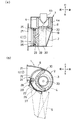
図1及び図2に示される空調ユニット1は、例えば車両のインストルメントパネルの下部のセンターに配置される縦型フルセンター置きタイプのもので、インテークボックス2とユニット本体3とで基本的に構成されている。
The
このうち、ユニット本体3は、インテークボックス2から空気を下流側に送るための送風機4、送風機4により送られてきた空気を冷却するエバポレータ等の冷却用熱交換器5、この冷却用熱交換器5で冷却された空気を再加熱するヒータコア等の加熱用熱交換器6、及び冷却用熱交換器5と加熱用熱交換器6との間に配置されて加熱用熱交換器6に送られる空気とバイパスする空気との割合を調整するエアミックスドア7をケーシング8内に収納している。尚、送風機4は、図2に示されるように、この実施形態では、1つのファン4aと1つのモータ4bとから構成されている。
Among them, the unit
また、ユニット本体3は、ケーシング8内に、加熱用熱交換器6に対し下流側となる車両進行方向前方側にて、前記加熱用熱交換器6で再加熱された空気が通過する温風通路9が形成されていると共に、冷却用熱交換器5の下流側からエアミックスドア7の回転軸に対しやや斜め上方にかけて冷風通路10が形成されている。
The unit
そして、ユニット本体3の温風通路9と冷風通路10とが合流するエアミックスチャンバ11よりも下流側において、ベント吹出用開口部12、13、デフ吹出用開口部(ベント吹出用開口部12と重なって隠れている。)、フット吹出用開口部14が、ケーシング8に適宜開口している。また、これらの実施形態では、加熱用熱交換器6の下流側からフット吹出用開口部14まで空気を案内するエアガイド壁15が形成されている。
Then, on the downstream side of the
前記吹出用開口部12、13は、その開口部周縁に当該開口部12、13を適宜開閉する吹出モード切換ドア16、17が揺動可能に配置されている。また、エアガイド壁15とケーシング8の外壁との間の流路上に吹出モード切換ドア18が揺動可能に配置されて、フット吹出用開口部14の開閉を可能にしている。
The blowing
これに対し、インテークボックス2は、ユニット本体3に対し車両幅方向に沿って左右のいずれか一方(この実施形態では右側)に配置されているもので、図2に示されるように、ケーシング8に形成された空気取入口20を介して前記ユニット本体3と連通しており、この空気取入口20は、送風機4のファン4aの空気取入口19と対峙している。
On the other hand, the
また、インテークボックス2は、特に図2(b)に示されるように、外気導入口21と内気導入口22とを有している。このうち、外気導入口21は、車両進行方向の前方に対し略対峙した状態で開口し、内気導入口22は、車両進行方向の前方に対し若干下方に向いて開口していると共に、外気導入口21が内気導入口22に対し車両の上側に並設されている。
Further, the
更に、内外気導入口21、22を適宜選択するためのインテークドアとしてスライドドア装置24が用いられている。このスライドドア装置24は、この実施形態では、ケーシング8の側面に対し一方端を外気導入口21から続く通風路の上面近傍部位とし他方端を内気導入口22の下方側端近傍部位とする略半円状に形成されたガイド部25と、このガイド部25に対し摺動可能に装着された略4分の1円の曲板状のスライドドア26と、スライドドア26の内側面に形成されたラック27と、インテークボックス2内に配置された駆動軸28の駆動ギア(ピニオン)29とで構成されている。
Further, a
このような構成により、外気導入モード時においては、図2(b)に示されるように駆動ギア29の回転をラック27に伝達させて、スライドドア26をガイド部25に沿ってガイド部25の下端まで摺動させ、外気導入口21を全開の状態にする。また、内気循環モード時においては、図示しないが、駆動ギア29を逆回転してその回転をラック27に伝達させて、スライドドア26をガイド部25に沿ってガイド部25の上端まで摺動させ、内気導入口22を全開の状態にする。
With such a configuration, in the outside air introduction mode, the rotation of the
そして、図2に示されるように、ケーシング8に形成された空気取入口20の全周を囲むようにして円筒状のフィルタ30もインテークボックス2内に収納されている。このフィルタ30は、内外気導入口21、22から侵入してきた水分や塵芥等を取り除くためのもので、その厚みは駆動軸28の駆動ギア29に接しない程度であると共にその軸方向に沿った長さはインテークボックス2の車両進行方向に沿った左右の内幅と略同じである。これにより、内外気導入口21、22から取入れられた空気は、ケーシング8の空気取入口20に到達するまでにフィルタ30を必ず通過するので、水分や塵芥等が送風機4内にまで侵入することを回避できる。
As shown in FIG. 2, a
以上の構成によれば、インテークドアとしてスライドドア24を採用するためドアを揺動するための揺動領域を確保する必要がないので、内外気導入口21、22とスライドドア24の摺動軌道(ガイド部25)との間にはほとんど余分な空間がない。また、スライドドア24の摺動軌道とフィルタ30との間も、フィルタ30の外形状に略沿う形でスライドドア24の摺動軌道が採られているので、ほとんど余分な空間がない。更に、フィルタ30とケーシング8の空気取入口20との間も、フィルタ30が空気取入口20の周縁に沿ってその全周を囲んで配置されているので余分な空間がない。よって、インテークボックス2内の余分な空間を従来例に比し大幅に削減することができるので、フィルタ30を収納する場合でもインテークボックス2の大型化を招かず、むしろフィルタ30を収納しないインテークボックス2よりも小型化を図ることも可能である。
According to the above configuration, since the sliding
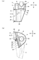
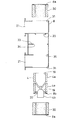
もっとも、フィルタ30は、図2に示す円筒状のものに限定されず、図3に示されるように、スライドドア24の円弧と同方向に膨らむ面を有する曲板状とし、その両端がケーシング8の内面に接するものとしても良い。これにより、フィルタ30は、空気取入口20の周縁のうちスライドドア24とは反対側の空気が回り込まない部位を残して囲むものとなり、当該空気が回り込まない部位を図3(a)の想像線に示すように切り欠くことが可能となるので、インテークボックス2のより一層の小型化を図ることができる。尚、図2に示す実施形態と同一の構成は同一の符号を付してその説明を省略した。
However, the
また、スライドドア装置24及びフィルタ30の形状、配置もインテークボックス2の小型化を図ることができればこれまでの実施形態と異なるものであっても良い。その一例を図4及び図5を用いて説明する。但し、送風機4や内外気導入口21、22等のこれまでの実施形態と同様の構成については同一の符号を付してその説明を省略した。
Further, the shape and arrangement of the sliding
このうち、スライドドア装置24は、ガイド部25、ラック27を有するスライドドア26、及び駆動ギア29を有する駆動軸28から構成される点では先の実施形態と同様であるが、このうち、ガイド部25は、ケーシング8の側面に対し一方端を外気導入口21から続く通風路の上面近傍部位とし、内気導入口22の開口端に略沿って延び、その他方端を内気導入口22の下方側端近傍部位として、斜め後方に向って延びる略直線状に形成されている。これに伴い、スライドドア26は、このガイド部25を上下に摺動可能とするために例えばガイド部25の長手方向寸法の略半分の長手方向寸法の平板状に形成されている。そして、駆動軸28は、図4の実施形態では、外気導入口21と内気導入口22との境界部分近傍において、スライドドア26に対し開口部22に近接するように外側に配置されている。これに伴い、スライドドア26のラック27も駆動軸28の駆動ギア29と噛み合うように外側に形成されている。但し、図5の実施形態に示されるように、駆動軸28は、外気導入口21と内気導入口22との境界部分近傍において、スライドドア26と下記するフィルタ30との間に配置されていても良い。この場合には、スライドドア26のラック27も駆動軸28の駆動ギア29と噛み合うようにフィルタ30側に形成されることとなる。
Among these, the
また、フィルタ30は、スライドドア26の摺動軌道に沿って内外気導入口21、22から続く通風路を塞ぐことが可能なように、斜め後方に向って延びる平板状をなしている一方で、その厚みは、空気取入口20を塞がないようにその周縁までの幅となっている。
In addition, the
以上の構成によっても、インテークドアとしてスライドドア24を採用するためドアを揺動するための揺動領域を確保する必要がないので、内外気導入口21、22とスライドドア24の摺動軌道(ガイド部25)との間にはほとんど余分な空間がない。また、スライドドア24の摺動軌道とフィルタ30との間も、スライドドア26とフィルタ30とが殆ど接した状態で並設されているので、余分な空間がない。更に、フィルタ30とケーシング8の空気取入口20との間も、フィルタ30が空気取入口20に対しその周縁に接しながら斜め下方に延びて配置されているので、ほとんど余分な空間がない。よって、インテークボックス2内の余分な空間を従来例に比し大幅に削減することができるので、フィルタ30を収納する場合でもインテークボックス2の大型化を招かず、むしろフィルタ30を収納しないインテークボックス2よりも小型化を図ることも可能である。
Even with the above configuration, since the sliding
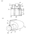
尚、フィルタ30が円筒状をなしている場合等に、図6に示されるように、このフィルタ30と接するケーシング8の部分をフィルタ30と略同形の円板状に切り欠いて蓋板8aとし、前記フィルタ30と一体にしたものとする。もっとも、フィルタ30と蓋板8とは連結されているのみでフィルタ30から取り外し可能としても良い。これにより、図6(b)に示すように、蓋板8aをケーシング8から外してフィルタ30の軸方向に沿って引っ張ることで、ケーシング8の送風機4とは反対側の外壁面にフィルタ30の挿通可能な開口部31が形成されて、この開口部31からフィルタ30がインテークボックス2内から引き出されるので、フィルタ30の交換作業を簡易に行うことができる。
When the
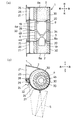
図7から図9において、これまでの実施形態とは異なる実施形態の車両用空調ユニット1が示されている。この空調ユニット1は、1のユニット本体3と2つのインテークボックス2とで構成されたものである。
7 to 9 show a vehicle
このうち、各インテークボックス2は、それぞれケーシング8に形成された空気取入口20を介して前記ユニット本体3と連通しており、この空気取入口20は、送風機4のファン4aの空気取入口19と対峙している。
Among these, each
また、各インテークボックス2は、特に図7(b)に示されるように、外気導入口21と内気導入口22とを1つずつ有している。このうち、外気導入口21は、車両進行方向の前方に対し略対峙した状態で開口し、内気導入口22は、車両進行方向の前方に対し若干下方に向いて開口していると共に、外気導入口21が内気導入口22に対し車両の上側に並設されている。
Each
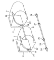
更に、各インテークボックス2は、内外気導入口21、22を適宜選択するためのインテークドアとしてスライドドア装置24を用いている。このスライドドア装置24は、図7及び図9では、ケーシング8の側面に対し一方端を外気導入口21から続く通風路の上面近傍部位とし他方端を内気導入口22の下方側端近傍部位とする略半円状に形成されたガイド部25と、このガイド部25に対し摺動可能に装着された略4分の1円の曲板状のスライドドア26と、スライドドア26の外側面に形成されたラック27と、インテークボックス2の外側のうち外気導入口21と内気導入口22との境界部位に配置された駆動軸28の駆動ギア(ピニオン)29とで構成されている。
Further, each
ここで、駆動軸28は、図9に示されるように、その長手方向の寸法を一方のインテークボックス2の外側面から他方のインテークボックス2の外側面までの長さと略同じとし、各スライドドア26のラック27と噛み合うための駆動ギア29が一対ずつ合計4個形成されたものとしても良い。これにより、2つのスライドドア26を一の駆動源(モータ)で摺動させることが可能となるので、各スライドドア26を別個の駆動源で駆動させる場合に比し構造が簡易化して部品点数が削減され、製造コストの削減を図ることができる。
Here, as shown in FIG. 9, the
以上の構成によれば、図7等に示される空調ユニット1にあっても、インテークドアとしてスライドドア24を採用するためドアを揺動するための揺動領域を確保する必要がないので、内外気導入口21、22とスライドドア24の摺動軌道(ガイド部25)との間にはほとんど余分な空間がない。また、スライドドア24の摺動軌道とフィルタ30との間も、フィルタ30の外形状に略沿う形でスライドドア24の摺動軌道が採られているので、ほとんど余分な空間がない。更に、フィルタ30とケーシング8の空気取入口20との間も、フィルタ30が空気取入口20の周縁に沿ってその全周を囲んで配置されているので余分な空間がない。よって、インテークボックス2内の余分な空間を従来例に比し大幅に削減することができるので、フィルタ30を収納する場合でもインテークボックス2の大型化を招かず、むしろフィルタ30を収納しないインテークボックス2よりも小型化を図ることも可能である。
According to the above configuration, even in the
尚、スライドドア装置24の構成は図7に示されるものに限定されず、図3に示されるように、フィルタ30を、スライドドア24と同方向に膨らむ面を有する曲板状とし、その両端がケーシング8の内面に接するものとすることで、当該フィルタ30について、空気取入口20の周縁のうちスライドドア24とは反対側の空気が回り込まない部位を残して囲むものとしても良い。また、図4や図5に示されるように、ガイド部25について、ケーシング8の側面に対し一方端を外気導入口21から続く通風路の上面近傍部位とし、内気導入口22の開口端に略沿って延び、その他方端を内気導入口22の下方側端近傍部位として、斜め後方に向って延びる略直線状に形成し、これに対応させて、スライドドア26について、このガイド部25を上下に摺動可能とするために例えばガイド部25の長手方向寸法の略半分の長手方向寸法の平板状に形成したものとしても良い。このような構成としても、上記の作用効果と同様の、クーリングユニットの小型化を図ることができるという作用効果を奏することができる。
The configuration of the
これに対し、ユニット本体2は、送風機4や冷却用熱交換器5等を収納し、送風機4と冷却用熱交換器5とは、図7(b)に示すように送風機4が冷却用熱交換器5に対し車両の上方となるように配置されている。送風機4は、2つのファン4aが車両幅方向に沿って左右に、当該ファン4aが相互に回転の妨げとならないように、配置されていると共に、この2つのファン4aを1つのモータ4bで駆動させるデュアルファン型を用いている。すなわち、送風機4は、この実施形態では、車両幅方向の左側のファン4aは中央側が窪み、車両幅方向の右側のファン4aは中央側が突出して、各々1つのモータ4bの回転軸に軸支されるようになっている。モータ4bは、この実施形態では、空気取入口20からインテークボックス2内で且つ円筒状のフィルタ30にあってはその筒内にまで突出している。
On the other hand, the unit
そして、ケーシング8に対し車両左右方向の略中央部位において、2つのファン4aの境界部分に向って延びて、ユニット本体2内を略車両左右方向に仕切る仕切り壁33が形成されている。この仕切り壁33の突出度は、ファン4aの外周側までであり、ファン4aの外形と略同じ形状の開口部34が形成されている。このようなユニット本体2の構成により、2つのインテークボックス2に開口した別個の内外気導入口21、22から空気を取り込むことを、2つのファン4aを回転させることで可能としている。
A
ところで、空調ユニット1は、この実施形態では、特に図9に示されるように、各インテークボックス2内に収納されるフィルタ30が円筒状の場合には、このフィルタ30と接するケーシング8の部分をフィルタ30と略同形の円板状に切り欠いて蓋板8aとし、前記フィルタ30と一体にしたものとしている。また、モータ4bが挿通する側の空気取入口20の周縁についてファン4aの外形状と略同じ外形状にてケーシング8から分離して空気取入口周縁部分8bとし、この空気取入口周縁部分8bはモータ4bと連結等して一体化されている。
By the way, in this embodiment, especially in this embodiment, as shown in FIG. 9, when the
これにより、2つのフィルタ30は、蓋板8aをケーシング8から外してフィルタ30の軸方向に沿って引っ張ることで、ケーシング8の送風機4とは反対側の外壁面にフィルタ30の挿通可能な開口部31が形成されるので、この開口部31からインテークボックス2外に引き出すことが可能である。このため、フィルタ30の交換作業を簡易に行うことができる。しかも、送風機4も、2つのファン4aがケーシング8の開口部34、35を通過することが可能であるので、フィルタ30を引き出した後に、同じ開口部31の一方から引き出すことが可能である。このため、送風機4のメンテナンス作業を空調ユニット1外で行うことができ、且つ送風機4全体での交換も可能であるので、空調ユニット1の保守点検が容易となる。
As a result, the two
1 車両用空調ユニット
2 インテークボックス
3 ユニット本体
4 送風機
4a ファン
4b モータ
5 冷却用熱交換器
8 ケーシング
8b 空気取入口周縁部分
19 送風機の空気取入口
20 ケーシングの空気取入口
21 外気導入口
22 内気導入口
24 スライドドア装置
25 ガイド部
26 スライドドア
27 ラック
28 駆動軸
29 駆動ギア
30 フィルタ
31 開口部
33 仕切り壁
34 開口部
35 開口部
DESCRIPTION OF
Claims (10)
前記ユニット本体は、前記送風機に対しモータの軸方向の外側にインテークボックスを有し、このインテークボックスにスライドドア及びフィルタが収納されていると共に、前記インテークボックスは、外気導入口と内気導入口とが、前記外気導入口が前記内気導入口に対し車両上方に配置されるように、車両進行方向の前方側に開口しており、
前記スライドドアは、車両上下方向に沿って移動することで前記外気導入口及び内気導入口の開度割合を調節し、
前記フィルタは、前記ケーシングに形成された空気取入口の周縁に対しその軸方向から見て近接していると共に前記スライドドアに沿って配置されていることを特徴とする車両用空調ユニット。 It has a unit body configured by housing a blower composed of a motor and a fan in at least a casing,
The unit body has an intake box on the outside of the motor in the axial direction with respect to the blower. A slide door and a filter are accommodated in the intake box, and the intake box includes an outside air introduction port, an inside air introduction port, However, the outside air introduction port is opened to the front side in the vehicle traveling direction so that the outside air introduction port is disposed above the vehicle with respect to the inside air introduction port
The sliding door adjusts the opening ratio of the outside air inlet and the inside air inlet by moving along the vehicle vertical direction,
The vehicle air-conditioning unit is characterized in that the filter is disposed close to the peripheral edge of the air intake port formed in the casing as viewed in the axial direction and along the slide door.
前記ユニット本体は、前記送風機に対しモータの軸方向の両外側に各々インテークボックスを有し、各インテークボックスにスライドドア及びフィルタが収納されていると共に、各インテークボックスは、外気導入口と内気導入口とが、前記外気導入口が前記内気導入口に対し車両上方に配置されるように、車両進行方向の前方側に開口しており、
前記スライドドアは、車両上下方向に沿って移動することで前記外気導入口及び内気導入口の開度割合を調節し、
前記フィルタは、前記ケーシングに形成された空気取入口の周縁に対しその軸方向から見て近接していると共に前記スライドドアに沿って配置されていることを特徴とする車両用空調ユニット。 A unit main body configured to accommodate at least a blower composed of one motor and two fans in a casing;
The unit main body has intake boxes on both outer sides in the axial direction of the motor with respect to the blower. Each intake box houses a slide door and a filter, and each intake box has an outside air inlet and an inside air introduction. And the opening is open to the front side in the vehicle traveling direction so that the outside air introduction port is disposed above the vehicle with respect to the inside air introduction port,
The sliding door adjusts the opening ratio of the outside air inlet and the inside air inlet by moving along the vehicle vertical direction,
The vehicle air-conditioning unit is characterized in that the filter is disposed close to the peripheral edge of the air intake port formed in the casing as viewed in the axial direction and along the slide door.
前記モータは、前記ケーシングの空気取入口の一方の周縁部分と一体に形成されて、当該空気取入口の周縁部分と共に着脱可能であり、
更に、前記ケーシングの双方のインテークボックスに対し、前記空気取入口周縁部分と一体に形成されたモータ及び前記フィルタの挿通可能な開口部が形成されていることを特徴とする請求項2、3、又は4に記載の車両用空調ユニット。 The partition wall that partitions the two fans of the blower has an opening through which the fan can be inserted,
The motor is formed integrally with one peripheral portion of the air intake port of the casing and is detachable together with the peripheral portion of the air intake port.
Furthermore, the opening part which can insert the motor and the said filter which were formed integrally with the said air inlet peripheral part with respect to the both intake boxes of the said casing is formed, Or the vehicle air-conditioning unit of 4.
Priority Applications (1)
| Application Number | Priority Date | Filing Date | Title |
|---|---|---|---|
| JP2004117558A JP2005297792A (en) | 2004-04-13 | 2004-04-13 | Air-conditioning unit for vehicle |
Applications Claiming Priority (1)
| Application Number | Priority Date | Filing Date | Title |
|---|---|---|---|
| JP2004117558A JP2005297792A (en) | 2004-04-13 | 2004-04-13 | Air-conditioning unit for vehicle |
Publications (1)
| Publication Number | Publication Date |
|---|---|
| JP2005297792A true JP2005297792A (en) | 2005-10-27 |
Family
ID=35329861
Family Applications (1)
| Application Number | Title | Priority Date | Filing Date |
|---|---|---|---|
| JP2004117558A Pending JP2005297792A (en) | 2004-04-13 | 2004-04-13 | Air-conditioning unit for vehicle |
Country Status (1)
| Country | Link |
|---|---|
| JP (1) | JP2005297792A (en) |
Cited By (8)
| Publication number | Priority date | Publication date | Assignee | Title |
|---|---|---|---|---|
| JP2007210526A (en) * | 2006-02-10 | 2007-08-23 | Calsonic Kansei Corp | Blower unit |
| JP2009023591A (en) * | 2007-07-23 | 2009-02-05 | Denso Corp | Air conditioner |
| JP2009515753A (en) * | 2005-11-14 | 2009-04-16 | スカニア シーブイ アクチボラグ(パブル) | Assembly for ventilating automotive driving compartment |
| WO2011114410A1 (en) | 2010-03-15 | 2011-09-22 | 株式会社ヴァレオジャパン | Vehicle air conditioning unit |
| JP2014240252A (en) * | 2013-06-12 | 2014-12-25 | 株式会社ケーヒン | Vehicular air conditioner |
| JP2014240251A (en) * | 2013-06-12 | 2014-12-25 | 株式会社ケーヒン | Vehicular air conditioner |
| KR101817748B1 (en) * | 2016-07-11 | 2018-01-11 | 임성구 | Air conditioner for vehicle |
| CN115635828A (en) * | 2022-10-24 | 2023-01-24 | 江铃汽车股份有限公司 | An economical and efficient air-conditioning box structure |
-
2004
- 2004-04-13 JP JP2004117558A patent/JP2005297792A/en active Pending
Cited By (8)
| Publication number | Priority date | Publication date | Assignee | Title |
|---|---|---|---|---|
| JP2009515753A (en) * | 2005-11-14 | 2009-04-16 | スカニア シーブイ アクチボラグ(パブル) | Assembly for ventilating automotive driving compartment |
| JP2007210526A (en) * | 2006-02-10 | 2007-08-23 | Calsonic Kansei Corp | Blower unit |
| JP2009023591A (en) * | 2007-07-23 | 2009-02-05 | Denso Corp | Air conditioner |
| WO2011114410A1 (en) | 2010-03-15 | 2011-09-22 | 株式会社ヴァレオジャパン | Vehicle air conditioning unit |
| JP2014240252A (en) * | 2013-06-12 | 2014-12-25 | 株式会社ケーヒン | Vehicular air conditioner |
| JP2014240251A (en) * | 2013-06-12 | 2014-12-25 | 株式会社ケーヒン | Vehicular air conditioner |
| KR101817748B1 (en) * | 2016-07-11 | 2018-01-11 | 임성구 | Air conditioner for vehicle |
| CN115635828A (en) * | 2022-10-24 | 2023-01-24 | 江铃汽车股份有限公司 | An economical and efficient air-conditioning box structure |
Similar Documents
| Publication | Publication Date | Title |
|---|---|---|
| JP5627922B2 (en) | Seal and discharge structure for front-rear integrated HVAC system | |
| CN102781692B (en) | Air Conditioning Units for Vehicles | |
| JP2018058472A (en) | Air conditioning unit for vehicle | |
| JP6604792B2 (en) | Blower | |
| JP7077989B2 (en) | Vehicle air conditioning unit | |
| KR100531087B1 (en) | Air Purifier Having Ventilating Function | |
| JP6234747B2 (en) | Air conditioner for vehicles | |
| KR102615039B1 (en) | Air conditioner and home appliance | |
| JP2008254643A (en) | Air conditioner for vehicle | |
| CN104228518A (en) | Automobile air conditioner | |
| JP2001158217A (en) | Automobile air conditioner | |
| JP6058522B2 (en) | Indoor unit | |
| JP5825182B2 (en) | Air conditioner | |
| JP4882318B2 (en) | Air conditioner | |
| CN101344288A (en) | Air conditioner | |
| JP5527302B2 (en) | Blower | |
| JP2006256427A (en) | Blower | |
| KR20100053100A (en) | Air conditioner | |
| JP4913460B2 (en) | Air conditioner for vehicles | |
| WO2023203945A1 (en) | Vehicle air-conditioning device | |
| JP6928999B2 (en) | Vehicle air conditioner | |
| JP2007090922A (en) | Air conditioning unit for vehicle | |
| JP2005104353A (en) | Air conditioning unit | |
| JP6504860B2 (en) | Vehicle air conditioner | |
| JP2006240599A (en) | Blowing device for vehicle |
Legal Events
| Date | Code | Title | Description |
|---|---|---|---|
| A621 | Written request for application examination |
Free format text: JAPANESE INTERMEDIATE CODE: A621 Effective date: 20070404 |
|
| A977 | Report on retrieval |
Free format text: JAPANESE INTERMEDIATE CODE: A971007 Effective date: 20090828 |
|
| A131 | Notification of reasons for refusal |
Effective date: 20090908 Free format text: JAPANESE INTERMEDIATE CODE: A131 |
|
| A02 | Decision of refusal |
Effective date: 20100126 Free format text: JAPANESE INTERMEDIATE CODE: A02 |