JP2005297775A - Integrated type stabilizer device for vessel - Google Patents
Integrated type stabilizer device for vessel Download PDFInfo
- Publication number
- JP2005297775A JP2005297775A JP2004116985A JP2004116985A JP2005297775A JP 2005297775 A JP2005297775 A JP 2005297775A JP 2004116985 A JP2004116985 A JP 2004116985A JP 2004116985 A JP2004116985 A JP 2004116985A JP 2005297775 A JP2005297775 A JP 2005297775A
- Authority
- JP
- Japan
- Prior art keywords
- stabilizer
- hull
- stabilizer element
- housing
- ship
- Prior art date
- Legal status (The legal status is an assumption and is not a legal conclusion. Google has not performed a legal analysis and makes no representation as to the accuracy of the status listed.)
- Pending
Links
- 239000003381 stabilizer Substances 0.000 title claims abstract description 63
- 238000005096 rolling process Methods 0.000 claims abstract description 18
- 230000000694 effects Effects 0.000 claims description 9
- XLYOFNOQVPJJNP-UHFFFAOYSA-N water Substances O XLYOFNOQVPJJNP-UHFFFAOYSA-N 0.000 claims description 5
- 230000008878 coupling Effects 0.000 claims description 3
- 238000010168 coupling process Methods 0.000 claims description 3
- 238000005859 coupling reaction Methods 0.000 claims description 3
- 230000000717 retained effect Effects 0.000 claims 1
- 238000013016 damping Methods 0.000 description 4
- 238000009434 installation Methods 0.000 description 3
- 208000031872 Body Remains Diseases 0.000 description 1
- 238000010586 diagram Methods 0.000 description 1
- 238000005339 levitation Methods 0.000 description 1
- 239000007788 liquid Substances 0.000 description 1
- 239000002184 metal Substances 0.000 description 1
- 238000000034 method Methods 0.000 description 1
- 238000005457 optimization Methods 0.000 description 1
- 230000002265 prevention Effects 0.000 description 1
- 238000007789 sealing Methods 0.000 description 1
Images

Landscapes
- Vehicle Body Suspensions (AREA)
- Vibration Prevention Devices (AREA)
Abstract
Description
本発明は、静止しているか、または低速で航行している船舶の運動、主としてはローリングを減衰するスタビライザー装置に関し、特に、非動作の場合に船舶船体表面の連続性を妨げないこの種のシステムに関する。 The present invention relates to a stabilizer device that damps the motion of a vessel that is stationary or traveling at low speed, mainly rolling, and in particular, such a system that does not impede the continuity of the vessel hull surface when not in operation. About.
静止しているか、または低速で航行している船舶においては、海の横成分によって発生するローリング運動が、客船および娯楽船の場合には、船舶の乗員を非常に不快にし、且つ投錨領域を制限する。漁船、海洋調査船、病院船および軍艦等の作業船の場合には、著しいローリング運動は多くの場合に作業性および安全性を低下させる。 On ships that are stationary or sailing at low speeds, the rolling motion generated by the transverse component of the sea makes ship occupants very uncomfortable and limits the throwing area in the case of passenger and recreational ships To do. In the case of work vessels such as fishing vessels, oceanographic survey vessels, hospital vessels and warships, significant rolling movements often reduce workability and safety.
これらの問題点を防止するため、スタビライザー装置が、主としてローリングの影響を極小化することを目的として、船舶に対して開発されてきた。この種の装置としては、本出願人によれば、以下のようなものが公知である。 In order to prevent these problems, stabilizer devices have been developed for ships mainly for the purpose of minimizing the effects of rolling. According to the present applicant, the following devices are known as this type of device.
ビルジキール(横揺れ防止棒): これは、最も基本的かつ最も単純なシステムを構成しており、通常喫水線と整合し、かつその長さ方向を横断する方向での船舶の揺動運動に抵抗を与えることによりローリング運動を制限する、船底に固定された2つの表面からなる。これらは、経済的ではあるが、効果はさほどでない解決法でしかなく、傾斜の増加を形成することにより船舶の前進運動に対する抵抗を増加させる。 Bilge keel (roll prevention bar): This constitutes the most basic and simplest system, which is normally aligned with the water line and resists the rocking motion of the ship in a direction transverse to its length. It consists of two surfaces fixed to the bottom of the ship that limit rolling motion by giving. These are economical, but less effective solutions, and increase resistance to forward movement of the ship by creating an increase in slope.
動的スタビライザー: 「固定された」と称することのできるこれらは、喫水線の下で船舶の側面から突出し、一般に、流体力学的断面を有するフィンで形される。これらは、船体の表面に垂直な幾何学的軸の周囲の回転運動を発生するために、通常電気油圧手段により駆動され、船舶のローリング運動を検出する装置により発せられる信号により制御される。前記フィンの流体力学的揚力により発生するトルクの方向は、船舶のローリング運動の方向とは反対であり、したがって後者が減衰される。動的スタビライザー装置は、スタビライザーフィンの急激な回転運動に基づいて、低速または静止した船舶のために開発されてきた。前進運動に対する抵抗となるのに加えて、この方法は、フィンの減衰効果が小さいことに起因する制限を有しており、また船舶の航行の通常状態下における抵抗の増加を構成する。 Dynamic stabilizers: These, which can be referred to as “fixed”, protrude from the side of the ship under the waterline and are generally shaped with fins having a hydrodynamic cross section. They are usually driven by electrohydraulic means and are controlled by signals emitted by a device for detecting the rolling motion of the ship in order to generate a rotational movement around a geometric axis perpendicular to the surface of the hull. The direction of the torque generated by the hydrodynamic lift of the fins is opposite to the direction of the vessel's rolling motion, so that the latter is damped. Dynamic stabilizer devices have been developed for low speed or stationary vessels based on the rapid rotational movement of the stabilizer fins. In addition to being resistant to forward motion, this method has limitations due to the small damping effect of the fins and constitutes an increase in resistance under normal conditions of vessel navigation.
フィンがその安定機能を発揮するためには、水が所定の速度で輪郭にぶつかる必要があるので、この種の動的スタビライザーは、船舶が移動している場合にのみ有効であり、船体上でのその構成および配置は、波が小さな状況での巡航速度において効果が最大となるように、通常計算される。 This kind of dynamic stabilizer is effective only when the ship is moving, because the fins need to hit the contours at a certain speed in order to perform its stable function, and on the hull Its configuration and arrangement are usually calculated so that the effect is maximized at cruising speed in small wave conditions.
これは効果的な装置ではあるが、技術的に複雑であるので、財政的費用の増大を招く。さらに、ビルジキールの場合と同様に、これを取り付けることは傾斜の増加を意味し、したがってあらゆる条件において前進運動に対する抵抗を与える。 While this is an effective device, it is technically complex and results in increased financial costs. Furthermore, as with the bilge keel, this means an increase in tilt and thus provides resistance to forward movement in all conditions.
動的スタビライザーのこの欠点を克服するため、使用していない場合には船舶の船体内に格納される格納式動的スタビライザーが開発されたが、この格納は船体内部の空間を減じることが明白である。その他の点については、これらのスタビライザーの操作は、前記した固定式動的スタビライザーの操作と同一である。 To overcome this shortcoming of dynamic stabilizers, retractable dynamic stabilizers have been developed that are stored inside the ship's hull when not in use, but this storage clearly reduces the space inside the hull. is there. In other respects, the operation of these stabilizers is the same as the operation of the fixed dynamic stabilizer described above.
減揺タンク: これらは、「水チャンバ」としても知られ、通常船舶の両側に配置されおり、かつ管と弁とからなるシステムを介して相互に連通している。これらの機能は、船舶の一方の側から他方に液体を移動し、船舶のローリング運動に抗する復元トルクを発生することによって、あらゆる条件下でローリングを減衰することにある。これは、用途が限られるものの効果的なシステムであるが、その取付けには高度な複雑性を伴い、船体内の容積を奪い、かつ或る状況では安定性の喪失を招くことになる。 Anti-vibration tanks: These are also known as “water chambers” and are usually located on both sides of the ship and communicate with each other via a system of pipes and valves. Their function is to damp rolling under all conditions by moving liquid from one side of the ship to the other and generating a restoring torque that resists the rolling motion of the ship. While this is an effective system with limited application, its installation involves a high degree of complexity, takes up the volume in the hull, and in some situations results in a loss of stability.
フィン付き円錐体: この装置は、実質的に円錐または円錐台形状であり、その小さい方の基部によって閉成されており、通常金属からなり、かつ表面にヒンジ連結されたフィンを備える本体、およびその下部から懸吊された重りを船舶の一方または両方の側部から吊り下げている。装置が懸吊されている側に向かって船舶が傾いた場合には、フィンが開き、重りの作用によって本体が沈んだままになる。傾きが反対側になると、円錐の表面上の水の抵抗が動きに抗する。これは、船舶が静止している場合にのみ使用可能な、単純で効果的な装置である。しかしながら、その取り付けおよび操作は複雑であり、クレーンまたは補助ダビット(吊り柱)の使用を必要とする。 Finned cone: The device is substantially conical or frustoconical, closed by its smaller base, usually made of metal and with fins hinged to the surface, and A weight suspended from the lower part is suspended from one or both sides of the ship. When the ship is tilted towards the side where the device is suspended, the fins open and the body remains submerged by the action of the weight. When the tilt is on the opposite side, the water resistance on the surface of the cone resists movement. This is a simple and effective device that can only be used when the ship is stationary. However, its installation and operation is complex and requires the use of cranes or auxiliary davits.
本発明の目的は、請求項1の特徴部分により、装置が非動作の場合に前進運動に抵抗を加えることなく、すなわち船舶の速度に影響を与えることなく、静止しているか、または低速で航行している船舶のローリングを効果的に減衰することが可能な、操作が単純かつ確実なスタビライザー装置を提供することである。 The object of the present invention is that, according to the features of claim 1, when the device is inactive, it does not resist forward movement, i.e. it does not affect the speed of the ship, it is stationary or sailing at low speed It is an object of the present invention to provide a stabilizer device that can effectively attenuate the rolling of a marine vessel that is simple and reliable in operation.
本発明の目的は、船舶が静止しているか、または低速で航行している場合の船舶のローリングを適当な程度まで十分に減衰させることのできる表面を有する第1の動作位置または展開位置と、船体と一体のヒンジを用いて動くことにより位置することができ且つ連続性を妨げられることなく船舶とともに表面を形成する第2の非動作位置または非展開位置とを選択することが可能な実質的にフィン形状の要素を、船の両側に取り付けることによって達成される。 The object of the present invention is to provide a first operating or deployed position having a surface that can sufficiently damp the rolling of the ship when the ship is stationary or navigating at low speed to a suitable extent; Substantially capable of selecting a second non-operating or non-deploying position that can be positioned by moving with a hinge integral with the hull and that forms a surface with the vessel without disturbing continuity This is accomplished by attaching fin-shaped elements to the sides of the ship.
前記第1の動作または展開条件において、ローリングの減衰効果は、その表面領域に垂直な流れの成分に対して前記要素の流体力学的抵抗が高いことによって直接的に達成される。 In the first operating or deployment condition, the rolling damping effect is achieved directly by the high hydrodynamic resistance of the element to the flow component normal to its surface area.
スタビライザー要素が、前記第2の非展開位置にあり、その外面が船体の同一平面上にある場合に、前進運動に対するその抵抗は事実上ゼロである。 When the stabilizer element is in the second undeployed position and its outer surface is in the same plane of the hull, its resistance to forward movement is virtually zero.
スタビライザー要素の動作表面およびその船体上の位置の両者、および各側に設置されたスタビライザー要素の数は、船体の形状に適合するものとし、また、船舶の横方向の安定性パラメータを考慮するものとする。 Both the working surface of the stabilizer element and its position on the hull, and the number of stabilizer elements installed on each side shall be adapted to the shape of the hull and shall take into account the lateral stability parameters of the ship And
本発明によるスタビライザー装置の導入により、以下の利点が達成される。
(1)船舶が静止しているか、または低速で航行している場合の減衰効果の最適化。他のシステムと比較して最大限の効率が達成される。
(1)単純な操作。
(2)前進運動に対する抵抗には影響がない。
(3)スタビライザー要素の動的機能を必要としない(本発明は、この形式のものも可能ではあるが)。
(4)船体への取り付けが内部空間にごく僅かな影響しか与えず、これにより新造船舶および既存船舶の両者への容易な設置を可能にする。
(5)船舶の速度に影響するような要素を構成しないため、特定の場合において、ローリング運動、ヒービング(heaving:上下揺れ)運動、ピッチング運動を制限するために、船体の種々の領域に多数の一体型スタビライザーを設置することの可能性を与える。
(6)船舶が危険な角度の傾きに達するのに要するエネルギー量が顕著に増加する必要があり、このことによって海上の状態が思わしくない場合の安全性が向上する。
With the introduction of the stabilizer device according to the invention, the following advantages are achieved.
(1) Optimization of the damping effect when the ship is stationary or navigating at low speed. Maximum efficiency is achieved compared to other systems.
(1) Simple operation.
(2) There is no effect on resistance to forward movement.
(3) Does not require the dynamic function of the stabilizer element (although this invention is also possible in this form).
(4) The attachment to the hull has a very slight effect on the internal space, thereby enabling easy installation on both new ships and existing ships.
(5) Since there are no elements that affect the speed of the ship, in certain cases there are a number of different areas of the hull to limit rolling, heaving, and pitching movements. Gives the possibility of installing an integrated stabilizer.
(6) The amount of energy required for the ship to reach a dangerous angle of tilt needs to increase significantly, which improves safety in situations where marine conditions are unintentional.
本発明の前記特徴、およびその他の特徴と利点は、添付の図面とともに本発明の実施例に関する以下の説明を読むことにより、当業者には明確となるであろう。 These and other features and advantages of the present invention will become apparent to those of ordinary skill in the art by reading the following description of embodiments of the invention in conjunction with the accompanying drawings.
以下において、添付図面を見ながら、実施例の説明を行なう。 Hereinafter, embodiments will be described with reference to the accompanying drawings.
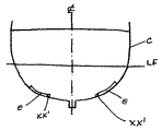
図1a、図1bから判るように、各スタビライザー要素は、喫水線の下で、船体Cの各側部に位置する少なくとも1つのフィンEから本質的になり、その構成は、それが船舶の前記船体Cに設けた凹部内に格納される、非動作、非展開(図1a参照)状態においては、その外面が船体の外面と同一平面上にあり、かつ連続性を中断することなく、前記船体Cと同一の輪郭で船体の外面と1つの面を形成する。この非動作位置において、図から判るように、スタビライザーフィンEは、船舶の航行に抵抗を与えない。 As can be seen from FIGS. 1a and 1b, each stabilizer element consists essentially of at least one fin E located on each side of the hull C below the waterline, the configuration of which is the said hull of the ship In a non-operating, non-expanded (see FIG. 1a) state stored in a recess provided in C, the outer surface of the hull C is flush with the outer surface of the hull and without interrupting continuity. The outer surface of the hull and one surface are formed with the same contour. In this inoperative position, as can be seen from the figure, the stabilizer fin E does not give resistance to the navigation of the ship.
スタビライザーフィンEはそれぞれ、軸線XX´(図1aおよび1bでは、図の平面に垂直となる)上にヒンジ連結されているので、図1aに示す非展開位置から図1bに示す少なくとも1つの動作、展開位置まで、軸線XX´の周りを回転することができる。軸線XX´は、浮揚水平面と実質的に平行または小さな角度を形成する。 Each stabilizer fin E is hinged on an axis XX ′ (in FIGS. 1a and 1b, perpendicular to the plane of the drawing), so that at least one movement shown in FIG. 1b from the undeployed position shown in FIG. 1a, It can be rotated about the axis XX ′ to the deployed position. The axis XX ′ forms a substantially parallel or small angle with the levitation water plane.
この図において、破線によって、図1に示す非動作状態のフィンEを受容するために、船体の各側部で船体C内部に設けられた密閉ハウジングAの輪郭を読み取ることができる。 In this figure, the outline of the sealed housing A provided inside the hull C can be read on each side of the hull to receive the non-operating fin E shown in FIG.
幾何学軸線XX´が、船体Cの事実上長手方向に配置されたヒンジ結合部は、ハウジングAの外部に設けられた支持部内に端部を回転支持されたシャフト(図示せず)を備えており、これによってフィンEが一体となる。前記ハウジングAの気密性は、従来の、慣例的な密封装置により保証され。 The hinge coupling portion in which the geometric axis XX ′ is arranged in the longitudinal direction of the hull C includes a shaft (not shown) whose end is rotatably supported in a support portion provided outside the housing A. Thus, the fin E is integrated. The hermeticity of the housing A is ensured by a conventional, conventional sealing device.
第1の、非展開または非動作位置から第2の、展開または動作位置への、およびそれとは逆へのフィンEの移動は、駆動力が対応するギアを介して各フィンEと一体のシャフトに伝達される電気モーター等の各種手段により、または、前記シャフトの少なくとも一端にシャフトを接続され、シャフトを回転させる油圧シリンダから少なくともなる手段により、達成することができる。油圧シリンダの数および前記シャフトに沿ったそれらの配置は、スタビライザーフィンEの大きさにより決まる。 The movement of the fin E from the first, non-deployed or non-operating position to the second, deployed or working position and vice versa is a shaft integral with each fin E via a gear to which the driving force corresponds. This can be achieved by various means such as an electric motor transmitted to the motor, or by means of at least a hydraulic cylinder having a shaft connected to at least one end of the shaft and rotating the shaft. The number of hydraulic cylinders and their arrangement along the shaft depends on the size of the stabilizer fin E.
同様に、各スタビライザーフィンEを、非展開位置および展開位置にしっかりと固定することを可能にする、航行の開始および終了時のための公知の種類のクランプ手段(図示せず)を設ける。 Similarly, a known type of clamping means (not shown) is provided for the start and end of the navigation that allows each stabilizer fin E to be securely fixed in the undeployed and deployed positions.
所望により、例えば非展開位置から、非展開位置と各フィンEの完全展開位置との間にある少なくとも1つの展開位置まで各フィンを回転させるために、各フィンEを駆動する手段を設ける。 Optionally, means for driving each fin E is provided to rotate each fin, for example, from a non-deployed position to at least one deployed position between the non-deployed position and the fully deployed position of each fin E.
また、本発明は、ハウジングA内の前記駆動手段の配置にも及ぶものであり、したがって、回転シャフトならびに対応する駆動および固定手段を有するフィンEの各アセンブリは、船体の外部、フィンEを収容する場合には前記のスタビライザーユニット全部を収容するような大きさを有するハウジングの内部に完全に適合することのできるスタビライザーユニットを構成する。 The invention also extends to the arrangement of the drive means in the housing A, so that each assembly of fins E having a rotating shaft and corresponding drive and fixing means accommodates the fin E outside the hull. In this case, a stabilizer unit that can be completely fitted into the inside of a housing having such a size as to accommodate the entire stabilizer unit is configured.
図1bに示す、スタビライザーフィンEの動作状態において、前記展開したフィンは、海の状態と船舶の状態によって決まる特定の角度にあり、フィンEは、ローリング運動に抗する復元モーメントを起こす流体力学的抵抗力F、F´を発生するであろう。 In the operating state of the stabilizer fin E shown in FIG. 1b, the unfolded fin is at a specific angle determined by the state of the sea and the state of the ship, and the fin E is a hydrodynamic that causes a restoring moment against rolling motion. Resistance forces F, F ′ will be generated.
図示しない代替例において、フィンEのそれぞれが少なくとも2つのフィン部分からなり、これらフィン部分は、非動作位置において、展開されておらず、かつハウジングA内に収容できるように、ヒンジ連結されている。フィンが第1の非動作状態から、第2の動作状態にまで移動する場合に、フィンEの前記展開されていない部分は展開され、船体Cから突出する。このようにして、各スタビライザー要素は、動作状態においては、船体C内に設けられた所定の大きさのハウジングAに比して増大した長さを有する。 In an alternative not shown, each of the fins E comprises at least two fin portions that are hinged so that they are not deployed and can be accommodated in the housing A in a non-operating position. . When the fin moves from the first non-operating state to the second operating state, the undeployed portion of the fin E is unfolded and protrudes from the hull C. In this way, each stabilizer element has an increased length compared to the housing A of a predetermined size provided in the hull C in the operating state.
最後に、本発明は、スタビライザー上での流体力学的流れの速度を増加させ、その結果、力がその上のローリングに抗するように、ローリング運動とは反対に、軸線の周りにスタビライザー要素を移動させることによる、スタビライザー要素の減衰効果を増大させる可能性にも及ぶ。 Finally, the present invention increases the speed of the hydrodynamic flow over the stabilizer so that the stabilizer element is placed around the axis as opposed to rolling motion so that the force resists rolling over it. It also extends to the possibility of increasing the damping effect of the stabilizer element by moving it.
A ハウジング
C 船体
E スタビライザー要素
F 流体力学的抵抗力
F´ 流体力学的抵抗力
XX´ ヒンジ結合部
A Housing C Hull E Stabilizer element F Hydrodynamic resistance F 'Hydrodynamic resistance XX' Hinge joint
Claims (9)
ヒンジ結合部(XX´)のみで船体(C)に結合された状態になる少なくとも1つの展開動作位置と、前記船体に設けたハウジング(A)中に受容され、かつ連続性を妨げられることなく外面が前記船体の残部内に組み込まれた状態になる非展開位置との間で、船体(C)に対して回転するように取り付けられた少なくとも1つのフィン状スタビライザー要素(E)と、
少なくとも1つの前記スタビライザー要素を、前記第1の非動作非展開位置と前記第2の動作展開位置との間で動かすための作動手段と、
前記少なくとも1つのスタビライザー要素を、前記第1および第2位置の各位置で動かないようにするクランプ手段とを含むことを特徴とする船舶用スタビライザー装置。 In a ship stabilizer device having a stabilizer element projecting from both sides of a hull,
At least one unfolding operation position that is coupled to the hull (C) only by the hinge coupling portion (XX ′), and is received in the housing (A) provided on the hull, and without continuity being hindered. At least one fin-like stabilizer element (E) mounted for rotation relative to the hull (C) between a non-deployed position where the outer surface is incorporated into the remainder of the hull;
Actuating means for moving at least one of the stabilizer elements between the first non-operating non-deployed position and the second working deployed position;
Clamp means for preventing the at least one stabilizer element from moving at each of the first and second positions.
前記スタビライザー要素が前記船体から突出する前記第2の動作位置にある場合に、前記スタビライザー要素の長さを増すために、前記少なくとも2つの部分を展開することが可能であることを特徴とする請求項1から請求項7までのいずれか一項に記載されたスタビライザー装置。 Each stabilizer element includes at least two interconnected portions in an undeployed state housed within the housing (A) of the hull (C) when the stabilizer element is in the non-operating position. Consists of
The at least two portions can be deployed to increase the length of the stabilizer element when the stabilizer element is in the second operating position protruding from the hull. The stabilizer apparatus as described in any one of Claim 1- Claim 7.
Priority Applications (1)
| Application Number | Priority Date | Filing Date | Title |
|---|---|---|---|
| JP2004116985A JP2005297775A (en) | 2004-04-12 | 2004-04-12 | Integrated type stabilizer device for vessel |
Applications Claiming Priority (1)
| Application Number | Priority Date | Filing Date | Title |
|---|---|---|---|
| JP2004116985A JP2005297775A (en) | 2004-04-12 | 2004-04-12 | Integrated type stabilizer device for vessel |
Publications (1)
| Publication Number | Publication Date |
|---|---|
| JP2005297775A true JP2005297775A (en) | 2005-10-27 |
Family
ID=35329846
Family Applications (1)
| Application Number | Title | Priority Date | Filing Date |
|---|---|---|---|
| JP2004116985A Pending JP2005297775A (en) | 2004-04-12 | 2004-04-12 | Integrated type stabilizer device for vessel |
Country Status (1)
| Country | Link |
|---|---|
| JP (1) | JP2005297775A (en) |
Cited By (1)
| Publication number | Priority date | Publication date | Assignee | Title |
|---|---|---|---|---|
| JP2018516797A (en) * | 2015-05-22 | 2018-06-28 | ハンフリー アクチエボラグHumphree Ab | Boat with adjustable device and stabilization device |
-
2004
- 2004-04-12 JP JP2004116985A patent/JP2005297775A/en active Pending
Cited By (1)
| Publication number | Priority date | Publication date | Assignee | Title |
|---|---|---|---|---|
| JP2018516797A (en) * | 2015-05-22 | 2018-06-28 | ハンフリー アクチエボラグHumphree Ab | Boat with adjustable device and stabilization device |
Similar Documents
| Publication | Publication Date | Title |
|---|---|---|
| KR101483507B1 (en) | Outboard motor | |
| JP5563103B2 (en) | Device for reducing flow resistance in moon pools | |
| US9266595B2 (en) | Retractable thruster unit for a marine vessel | |
| JP7486969B2 (en) | Active stabilization device and method | |
| KR100506429B1 (en) | High-velocity rudder | |
| CN110395365B (en) | Rotor type full-navigational-speed vector ship stabilizer | |
| US20040011269A1 (en) | Integral stabilizer system for vessels | |
| CN102333693A (en) | Ice-breaking system for floating bodies | |
| JP2004182096A (en) | Vessel, navigation device of vessel, rudder angle control device of vessel, and rudder angle control method for vessel | |
| JP4078421B2 (en) | Amphibious ship | |
| JP2010013087A (en) | Marine vessel | |
| JP2005297775A (en) | Integrated type stabilizer device for vessel | |
| US20050011427A1 (en) | Two degree of freedom rudder/stabilizer for waterborne vessels | |
| CN108891550A (en) | A kind of double floating body semi-submerged ships subtracting swing mechanism and the application mechanism | |
| KR102677951B1 (en) | Thruster with foldable wing and vessel including the same | |
| KR101468227B1 (en) | Control of Rolling Motion using Variable Bilge Kill of Ship and Offshore Structures | |
| KR20170047302A (en) | A vessel comprising a propulsion unit | |
| JP7148329B2 (en) | Rudder blades and ships | |
| CN116605395A (en) | A propulsion device for an engineering ship | |
| KR20130055875A (en) | Controllerable area rudder for vessel | |
| GR20210100165A (en) | DEVICE FOR DAMPING VESSEL OSCILLATIONS | |
| JP2008068796A (en) | Propulsion method and device for marine vessel | |
| JP3089898B2 (en) | Offshore structure rocking device | |
| KR102095417B1 (en) | Active type anti-rolling equipment | |
| NO320143B1 (en) | Integrated stabilization system for vessels |