JP2005297718A - Power steering device - Google Patents
Power steering device Download PDFInfo
- Publication number
- JP2005297718A JP2005297718A JP2004115729A JP2004115729A JP2005297718A JP 2005297718 A JP2005297718 A JP 2005297718A JP 2004115729 A JP2004115729 A JP 2004115729A JP 2004115729 A JP2004115729 A JP 2004115729A JP 2005297718 A JP2005297718 A JP 2005297718A
- Authority
- JP
- Japan
- Prior art keywords
- steering
- electric motor
- electric
- power steering
- electric power
- Prior art date
- Legal status (The legal status is an assumption and is not a legal conclusion. Google has not performed a legal analysis and makes no representation as to the accuracy of the status listed.)
- Pending
Links
Images


Landscapes
- Steering Control In Accordance With Driving Conditions (AREA)
- Power Steering Mechanism (AREA)
Abstract
【課題】
ステアリング系を操舵補助するための複数の電動モータを備え、該複数の電動モータのうち少なくとも一つの電動モータの駆動軸にクラッチ機構を採用することによって、同期制御を容易化し、高出力化を可能にするとともに、総合的なエネルギコストの低減を図り、操舵性の向上を図った電動パワーステアリングを提供する。
【解決手段】
ステアリング系を操舵補助するための複数の電動モータと、該電動モータの動作を負荷状態に応じて個別に制御するための制御手段とを備え、少なくとも一つの電動モータは、逆作動のトルク伝達が空転するクラッチ機構を備えた。
【選択図】図1【Task】
Equipped with a plurality of electric motors to assist the steering system, and adopting a clutch mechanism on the drive shaft of at least one of the plurality of electric motors facilitates synchronous control and enables higher output In addition, an electric power steering system is provided in which overall energy costs are reduced and steering performance is improved.
[Solution]
A plurality of electric motors for assisting steering of the steering system, and control means for individually controlling the operation of the electric motors according to the load state. Equipped with an idle clutch mechanism.
[Selection] Figure 1
Description
本発明は、自動車もしくは産業車両に用いられる電動パワーステアリング装置の改良に関する。 The present invention relates to an improvement in an electric power steering device used for an automobile or an industrial vehicle.
一般に、電動パワーステアリング装置には、操舵補助用の電動モータをコラム部に設けたコラム操舵補助式、ピニオン部に設けたピニオン操舵補助式、ラック部に設けたラック操舵補助式、およびボールスクリュー部に設けたボールスクリュー式の4種類が存在している。 Generally, in an electric power steering apparatus, a column steering assist type in which an electric motor for assisting steering is provided in a column portion, a pinion steering assist type provided in a pinion portion, a rack steering assist type provided in a rack portion, and a ball screw portion There are four types of ball screw type provided in.
このような電動パワーステアリング装置は、油圧式のものに較べ、走行条件に応じた細かい制御が可能であるという利点から、近年、自動車に広く用いられている。 Such an electric power steering device has been widely used in automobiles in recent years because of the advantage that fine control according to traveling conditions is possible as compared with a hydraulic type.
しかし、電動パワーステアリング装置は、油圧式のものに較べ、出力が小さいという欠点から、中型、大型自動車への適用が困難であった。仮に、電動モータを大きくすれば、高出力を得ることはできるが、電動モータを大型化することは、設置スペースの面で限界があり、組立工程における作業面、コスト面においても得策ではなかった。 However, the electric power steering device has been difficult to apply to medium-sized and large-sized automobiles due to the disadvantage that the output is smaller than that of the hydraulic type. If the electric motor is made larger, high output can be obtained, but increasing the size of the electric motor is limited in terms of installation space, and it was not a good solution in terms of work and cost in the assembly process. .
そのため、電動パワーステアリング装置で、電動モータの出力を高める技術として、小型電動モータを2基併設したものが、例えば特許文献1、特許文献2、および特許文献3に開示される。
Therefore, as a technology for increasing the output of the electric motor in the electric power steering device, two small electric motors are disclosed in Patent Document 1,
特許文献1では、ステアリングコラムに、2台の操舵補助用電動モータを取付け、この2台の電動モータ回転力を、ステアリングシャフトに負荷して操舵機構に伝達するようになっているコラム操舵補助式の電動パワーステアリング装置が開示されている。 In Patent Document 1, two steering assisting electric motors are attached to a steering column, and the torque of the two electric motors is loaded on a steering shaft and transmitted to a steering mechanism. An electric power steering apparatus is disclosed.
また、特許文献2では、上記コラム操舵補助式の電動パワーステアリング装置の他に、ラック・ピニオン部に2台の操舵補助用電動モータを取り付けたラック・ピニオン式の電動パワーステアリング装置が開示されている。
Further,
さらに、特許文献3では、図14に示すように、操舵補助用の電動モータ101は、出力軸101aの途中に電磁クラッチ102を介在させて第1の減速機構103を構成するウォームギア104が装着され、また操舵補助用の電動モータ105は、出力軸105aの途中に同じく電磁クラッチ106を介在させるとともに、第2の減速機構107を介在させて第1の減速機構103を構成するウォームギア108が装着されている。そして、電磁クラッチ102,106は、車速が零から所定値の範囲内で常に継位置に設定され、車速が所定値を超えると、電磁クラッチ102は継状態のままに保持される一方、電磁クラッチ106は制御部によって断状態に切りかえられるようになっている。
Further, in
ところが、特許文献1および特許文献2では、いずれの電動モータも路面側からの逆作動が入力される構成になっていた。電動モータを制御する際には、逆作動の入力は1つあれば十分であるが、上記従来の電動パワーステアリング装置では、いずれの電動モータも逆作動を入力してしまうため、電動モータへの負荷が大きく、消費電力が大きかった。
However, in Patent Document 1 and
また、特許文献3では、低速時には、電磁クラッチ102,106は共に継状態であるので、電動モータ101,105は共に路面側からの逆作動力を入力してしまい、電動モータの消費電力を低減することはできなかった。また、電磁クラッチ102,106の継,断操作を制御するための制御装置等を設ける必要があり、これらを取り付けるための労力およびコストが嵩んでしまうという問題があった。さらに、電動モータ101,105と電磁クラッチ102,106との連結部に対する設計の不的確化を招く虞れがあった。
Further, in
そこで、本発明は、上記事情に鑑みてなされたものであり、本発明の目的は、ステアリング系を操舵補助するための複数の電動モータを備え、該複数の電動モータのうち少なくとも一つの電動モータの駆動軸にクラッチ機構を採用することによって、同期制御を容易化し、高出力化を可能にするとともに、総合的なエネルギコストの低減を図り、操舵性の向上を図った電動パワーステアリングを提供することにある。 Accordingly, the present invention has been made in view of the above circumstances, and an object of the present invention includes a plurality of electric motors for assisting steering of a steering system, and at least one of the plurality of electric motors. By adopting a clutch mechanism on the drive shaft of the motor, it is possible to facilitate the synchronous control, enable higher output, reduce the overall energy cost, and provide an electric power steering system that improves the steering performance There is.
本発明の上記目的は、ステアリング系を減速機構を介して操舵補助するための複数の電動モータと、該電動モータの動作を負荷状態に応じて個別に制御するための制御手段とを備え、少なくとも一つの前記電動モータは、逆作動のトルク伝達が空転するクラッチ機構を備えたことにより、達成される。 The above object of the present invention includes a plurality of electric motors for assisting steering through a speed reduction mechanism, and a control means for individually controlling the operation of the electric motors according to the load state. One electric motor is achieved by including a clutch mechanism in which reverse torque transmission is idle.
また、上記目的は、前記制御手段は、負荷状態に起因するモータ特性変動を補償するようにしたことにより、効果的に達成される。 Further, the above object is effectively achieved by the control means compensating for the motor characteristic fluctuation caused by the load state.
また、上記目的は、前記モータ特性変動は、前記電動モータのトルク変動であることにより、効果的に達成される。 Further, the above object is effectively achieved by the motor characteristic fluctuation being torque fluctuation of the electric motor.
また、上記目的は、前記モータ特性変動は、車両特性により前記ステアリング系に発生する振動であることにより、効果的に達成される。 Further, the object is effectively achieved by the motor characteristic fluctuation being vibration generated in the steering system due to vehicle characteristics.
また、上記目的は、前記電動モータは、ステアリングコラムに配されたことにより、効果的に達成される。 Further, the above object is effectively achieved by arranging the electric motor on the steering column.
また、上記目的は、前記電動モータは、ステアリングコラムと、ステアリングピニオン部とに配されたことにより、効果的に達成される。 Further, the above object is effectively achieved by arranging the electric motor in the steering column and the steering pinion portion.
また、上記目的は、前記電動モータは、ステアリングピニオン部に配されたことにより、効果的に達成される。 Moreover, the said objective is effectively achieved because the said electric motor was distribute | arranged to the steering pinion part.
また、上記目的は、前記電動モータは、ステアリングピニオン部と、ラック部とに配されたことにより、効果的に達成される。 Moreover, the said objective is effectively achieved by the said electric motor being distribute | arranged to the steering pinion part and the rack part.
また、上記目的は、前記クラッチ機構を備えた前記電動モータは、ステアリングピニオン部に配されるとともに、前記クラッチ機構を備えていない前記電動モータは、ボールスクリュー部に配されたことにより、効果的に達成される。 In addition, the above object is effective because the electric motor having the clutch mechanism is arranged in a steering pinion portion, and the electric motor not having the clutch mechanism is arranged in a ball screw portion. To be achieved.
また、上記目的は、前記電動モータは、ステアリングコラムと、ボールスクリュー部とに配されたことにより、効果的に達成される。 Moreover, the said objective is effectively achieved by having arrange | positioned the said electric motor to a steering column and a ball screw part.
さらに、上記目的は、前記クラッチ機構を備えた前記電動モータは、ステアリングコラムに配されるとともに、前記クラッチ機構を備えていない前記電動モータは、ボールスクリュー部に配されたことにより、効果的に達成される。 Further, the object is that the electric motor provided with the clutch mechanism is arranged in a steering column, and the electric motor not provided with the clutch mechanism is arranged in a ball screw portion, thereby effectively Achieved.
以上のように、本発明に係る電動パワーステアリング装置によると、ステアリング系を減速機構を介して操舵補助するための複数の電動モータと、該電動モータの動作を負荷状態に応じて個別に制御するための制御手段とを備えた。これにより、ステアリング系に作用する負荷を分散することができ、高出力化が可能になり、且つ電動モータの小型化を図り、電動モータを配する設置スペースを軽減することができる。この結果、小型車両のみならず、大型車両に対しても電動パワーステアリング装置を適用することができる。 As described above, according to the electric power steering device of the present invention, the plurality of electric motors for assisting the steering of the steering system via the speed reduction mechanism, and the operation of the electric motors are individually controlled according to the load state. Control means. As a result, the load acting on the steering system can be distributed, the output can be increased, the electric motor can be reduced in size, and the installation space for arranging the electric motor can be reduced. As a result, the electric power steering apparatus can be applied not only to small vehicles but also to large vehicles.
また、電動モータのうち少なくとも一つの電動モータの駆動軸に、逆作動が伝達されないように構成されたクラッチ機構を採用し、路面側からの逆作動力が入力されないようにした。これにより、一方の電動モータには逆作動力が入力されないため、総合的なエネルギコストの低減を図ることができ、且つ電動モータの小型化および損傷防止を図ることができる。 In addition, a clutch mechanism configured to prevent reverse operation from being transmitted to the drive shaft of at least one of the electric motors is employed so that reverse operation force from the road surface side is not input. Thereby, since no reverse operating force is input to one electric motor, the overall energy cost can be reduced, and the electric motor can be reduced in size and prevented from being damaged.
また、複数の電動モータを個別に制御することにより、細かな制御が可能になり、車両の走行状態に応じて操舵補助力を簡単に制御することができるとともに、走行時のモータ慣性も小さくなり、操舵性を向上させることができる。 In addition, by individually controlling a plurality of electric motors, fine control is possible, and the steering assist force can be easily controlled according to the traveling state of the vehicle, and the motor inertia during traveling is also reduced. Steerability can be improved.
さらに、エンジンや車体サイズの変更の際に、一方の電動モータを共通にして、他方の電動モータのサイズを変更してステアリング系に配することで対応することにより、製造コストを低減できるとともに、取付けに要する労力を軽減できる。 Furthermore, when changing the size of the engine and the vehicle body, by making one electric motor in common and changing the size of the other electric motor and arranging it in the steering system, it is possible to reduce the manufacturing cost, Labor required for installation can be reduced.
以下、図面を参照にしながら、本発明の実施形態を説明する。 Hereinafter, embodiments of the present invention will be described with reference to the drawings.
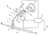
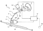
図1は、本発明の実施例1に係る電動パワーステアリング装置1aを示す概略構成図である。同図において、電動パワーステアリング装置1aは、ステアリングシャフト2をステアリングコラム3内で回転自在に支持しており、ステアリングホイール4の操舵力を、ユニバーサルジョイント5を介してインタミシャフト6に伝動するようになっている。
FIG. 1 is a schematic configuration diagram illustrating an electric power steering apparatus 1a according to a first embodiment of the present invention. In the figure, an electric power steering apparatus 1 a supports a
また、インタミシャフト6は、ユニバーサルジョイント7を介してピニオン軸8に連結され、ステアリングギア部9によって車両幅方向に延びるラック軸10に連結されている。このステアリングギア部9では、ピニオン軸8のピニオン歯(ピニオン)とラック軸10のラック歯(ラック)との噛合によって、ピニオン軸8の回転運動をラック軸10の直線運動に変換するようになっている。
The intermediate shaft 6 is connected to a
また、ステアリングコラム3の下端側(図1左方)には、電動モータ11Aが設けられ、図2に示すように、後端側(図2左側)に、減速機構12Aが一対の玉軸受13,13によって回転自在に支持されている。この減速機構12Aは、ステアリングシャフト2に圧入固定されたウォームホイール14と、該ウォームホイール14に噛合するウォームギア15とから構成される。これにより、電動モータ11Aが駆動すると、その駆動軸16に連結されたウォームギア15およびウォームホイール14を介してステアリングシャフト2を操舵補助するようになっている。
Further, an
また、ステアリングコラム3の上端側(図1右方)には、電動モータ11Bが設けられ、上述したものと同様の減速機構12Bを介してステアリングシャフト2を操舵補助するようになっている。
Further, an
また、各電動モータ11A,11Bの駆動を制御する制御手段(ECU)17には、ステアリングシャフト2に取り付けられたトルクセンサ18から、ステアリングホイール4の操作で与えられた操舵トルクに基づく信号が入力される。また、ECU17には、車速センサ19から、車速信号が入力される。
A control unit (ECU) 17 that controls the driving of each of the
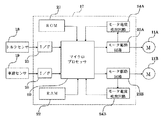
ECU17は、図3に示すように、所定のプログラムにより電動モータ11A,11Bの駆動制御を司るマイクロプロセッサ20と、プログラムや予め決められた定数などを記憶したROM21と、マイクロプロセッサ20のワークエリアや一時記憶として使用されるRAM22と、各電動モータ11A,11Bごとの駆動を制御するためのモータ駆動回路23A,23Bと、各電動モータ11A,11Bの供給電流を検出するモータ電流検出回路24A,24Bと、トルクセンサ18および車速センサ19からの信号を受信するI/Oインターフェイス(I/F)25,25とから構成されている。
As shown in FIG. 3, the
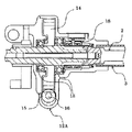
この電動パワーステアリング装置1aにおいては、図4に示すように、電動モータ11Aに連結している駆動側軸16aと減速機構12Aに連結している被駆動側軸16bとの間にクラッチ機構26が設けられている。このクラッチ機構26は、電動モータ11Aによる駆動側軸16aの正逆回転トルクを被駆動側軸16bに伝達する一方、被駆動側軸16bの正逆回転トルクを、駆動側軸16aと被駆動側軸16bとを空転させることによって伝達しない構造になっている。
In this electric power steering apparatus 1a, as shown in FIG. 4, a
図4において、駆動側軸16aおよび被駆動側軸16bは、軸受27および軸受28を介してケース29に回転自在に支持されている。このクラッチ機構26は、駆動側軸16aに一体に形成された駆動側部材30と、被駆動側軸16bに一体に形成された被駆動側部材(外輪)31と、駆動側部材30の外周面30aと外輪31の摩擦面31aとの間に介在され、慣性体として作用する複数の転動体32とからなる。
In FIG. 4, the
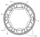
図5に示すように、転動体32は、駆動側部材30から径方向外方に突出する突起部33に係止されたバネ34と係合することによって、位置を保持されている。このバネ33は、図6に示すように、変位自在に形成された舌バネ部35を有し、該舌バネ部35は、転動体32を径方向内方(外周面30a側)に弾性的に押圧している。
As shown in FIG. 5, the rolling
また、転動体32は、一般的な円筒ころ軸受を構成する円筒ころの如きもので、高炭素クロム軸受鋼等の硬質金属からなり、外力が加わらない状態では、円周方向における各突起部33間の中間に位置している。なお、この状態では、転動体32と外輪31の摩擦面31aとは、擦れ合うことはない。
Further, the rolling
次に、このクラッチ機構26を組み込んだクラッチ付モータ11Aの作用について説明する。まずステアリング系を操舵補助するために、駆動側軸16aの回転を被駆動側軸16bに伝達する場合について説明する。例えば、モータ11Aが回転し、駆動側部材30が図5の反時計回りに回転する場合には、この駆動側部材30の回転時の回転加速度による転動体32の慣性によって、転動体32は、円周方向における各突起部33間の中間位置から僅かにずれる。これにより、転動体32は、バネ34のバネ力に抗して外輪31の円周方向外方に変位し、駆動側部材30の外周面30aと外輪31の摩擦面31aとの間に嵌合する。この結果、駆動側軸16aと被駆動側軸16bとが係合し、同速度で回転するようになっている。
Next, the operation of the clutch-equipped
なお、上述の説明は、駆動側部材30が反時計回りに回転した場合について述べたが、時計方向に回転する場合も、回転方向が逆になる以外、同様に作用する。
In the above description, the case where the
次に、モータ11Aは静止しており、駆動側部材30が静止状態であるにも拘わらず、転蛇輪からの逆作動力によって、被駆動軸16bおよび外輪31に回転方向の力が加わった場合について説明する。例えば、外輪31が図5の反時計回りに回転する場合には、転動体32は、バネ34のバネ力によって円周方向おける各突起部33間の中間位置から不動である。よって、外輪31の摩擦面31aと転動体32の転動面とが当接することはない。また、仮に、外輪31の摩擦面31aと転動体32の転動面とが当接した状態で、外輪31に回転方向の力が加わった場合には、所定の角度回転することによって、転動体32の嵌合は解除される。このように、外輪31の回転方向に力が加わった場合には、外輪31は空転するため、この回転方向の力が駆動側部材30に伝達されることはない。
Next, the motor 11 </ b> A is stationary, and a rotational force is applied to the driven
なお、上述の説明は、外輪31が反時計回りに回転した場合について述べたが、時計方向に回転する場合も、回転方向が逆になる以外、同様に作用する。
In the above description, the case where the
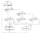
次に、本実施例の電動パワーステアリング装置の作用について、図7のフローチャート図に基づいて説明する。 Next, the operation of the electric power steering apparatus of this embodiment will be described based on the flowchart of FIG.
まず、ステップS1では、トルクセンサ18から検出された操舵トルクT、および車速センサ19から検出された車速Sを読み取る。
First, in step S1, the steering torque T detected from the
ステップS2では、車速Sが決められた高速基準値RS1を超えているか、否かを判定する。車速Sが高速基準値RS1を超えているときは、高速走行中であると判断し、ステップS3に移行する。 In step S2, it is determined whether or not the vehicle speed S exceeds a determined high speed reference value R S1 . When the vehicle speed S exceeds the high speed reference value R S1 , it is determined that the vehicle is traveling at high speed, and the process proceeds to step S3.
ステップS3では、操舵トルクTが決められた大トルク基準値RT1を超えているか、否かを判定する。操舵トルクTが大トルク基準値RT1超えているときは、ステアリングホイール4から大きな操舵トルクが入力されていると判断し、ステップS4に移行する。操舵トルクTが大トルク基準値RT1以下であるときは、ステアリングホイール4から大きな操舵トルクが入力されていないと判断し、ステップS5に移行する。
In step S3, whether the above atmospheric torque reference value R T1 the steering torque T is determined, it determines whether. When the steering torque T exceeds the large torque reference value RT1 , it is determined that a large steering torque is input from the
高速走行中であり、且つ入力された操舵トルクTが大トルク基準値RT1を超えているときは、ステップS4で、クラッチ無しモータ11Bとクラッチ付モータ11Aとを共に駆動し、操舵補助するようになっている。高速走行中に、衝突回避するためにハンドル操作する際には、ステアリングシャフト2に大きな操舵トルクが発生する。そのため、高速走行中であっても、大きな操舵トルクTが検出されたときには、クラッチ無しモータ11Bとクラッチ付モータ11Aとを共に駆動し、操舵補助するようになっている。
A high speed traveling, and when the input steering torque T exceeds the large torque reference value R T1 in step S4, so that drive both the
高速走行中であり、且つ入力された操舵トルクTが大トルク基準値RT1以下であるときは、ステップS5で、クラッチ無しモータ11Bのみを駆動し、操舵補助するようになっている。高速走行中では、大きな操舵トルクTが入力されていないときには、過大な操舵補助力を必要としないため、クラッチ無しモータ11Bのみによって、操舵補助するようになっている。
A high speed traveling, and when the input steering torque T is equal to or less than the high torque reference value R T1 in step S5, by driving only
次いで、ステップS2で車速Sが高速基準値RS1以下であるときは、ステップS6に移行し、車速Sが決められた低速基準値RS2(RS2<RS1)を超えているか、否かを判定する。車速Sが低速基準値RS2を超えているときは、中速走行中であると判断し、ステップS7に移行する。 Next, when the vehicle speed S is equal to or less than the high speed reference value R S1 in step S2, the process proceeds to step S6, whether or not the vehicle speed S exceeds the determined low speed reference value R S2 (R S2 <R S1 ). Determine. When the vehicle speed S exceeds the low speed reference value RS2 , it is determined that the vehicle is traveling at a medium speed, and the process proceeds to step S7.
ステップS7では、ステップS3と同様に、操舵トルクTが決められた大トルク基準値RT1を超えているか、否かを判定する。操舵トルクTが大トルク基準値RT1超えているときは、ステアリングホイール4から大きな操舵トルクが入力されていると判断し、ステップS4に移行する。操舵トルクTが大トルク基準値RT1以下であるときは、ステップS5に移行する。
In step S7, similarly to step S3, or exceeds the large torque reference value R T1 the steering torque T is determined, determines whether. When the steering torque T exceeds the large torque reference value RT1 , it is determined that a large steering torque is input from the
中速走行中であり、且つ入力された操舵トルクTが大トルク基準値RT1を超えているときは、ステップS4で、クラッチ無しモータ11Bとクラッチ付モータ11Aとを共に駆動し、操舵補助するようになっている。この場合の車速Sおよび操舵トルクTは、通常の道路で行なわれるUターンなどの際の車速および操舵トルクであり、大きなトルクを必要とするため、クラッチ無しモータ11Bとクラッチ付モータ11Aとを共に駆動し、操舵補助する必要がある。
A medium-speed traveling, when and inputted steering torque T exceeds the large torque reference value R T1, at step S4, to drive both the
中速走行中であり、且つ入力された操舵トルクTが大トルク基準値RT2以下であるときは、ステップS5で、クラッチ無しモータ11Bのみを駆動し、操舵補助するようになっている。中速走行中であり、操舵トルクTが過大に大きくない場合には、大きな操舵補助力を必要としないため、クラッチ無しモータ11Bのみによる操舵補助で十分である。
When the vehicle is traveling at medium speed and the input steering torque T is less than or equal to the large torque reference value RT2 , only the motor without clutch 11B is driven to assist steering in step S5. When the vehicle is traveling at a medium speed and the steering torque T is not excessively large, a large steering assist force is not required, so that the steering assist only by the
ステップS6で、車速Sが低速基準値RS2以下であるときは、低速走行中であると判断し、ステップS8に移行する。ステップS8では、操舵トルクTが決められた小トルク基準値RT2を超えているか、否かを判定する。操舵トルクTが小トルク基準値RT2以下であるときは、ステアリングホイール4から入力されている操舵トルクが小さくないと判断し、ステップS4に移行する。操舵トルクTが小トルク基準値RT2以下であるときは、ステアリングホイール4から入力されている操舵トルクが小さいと判断し、ステップS5に移行する。
If the vehicle speed S is equal to or lower than the low speed reference value R S2 in step S6, it is determined that the vehicle is traveling at a low speed, and the process proceeds to step S8. In step S8, it is determined whether or not the steering torque T exceeds the determined small torque reference value RT2 . When the steering torque T is less than or equal to the small torque reference value RT2, it is determined that the steering torque input from the
低速走行中であり、且つ入力された操舵トルクTが小トルク基準値RT2を超えているときは、ステップS4で、クラッチ無しモータ11Bとクラッチ付モータ11Aとを共に駆動し、操舵補助するようになっている。この場合は、主に車庫入れや縦列駐車などの際のハンドル操作であり、ハンドルの据え切り時には、大きなトルクを必要とする。よって、この場合には、クラッチ無しモータ11Bとクラッチ付モータ11Aとを共に駆動し、操舵補助するようになっている。
When the vehicle is traveling at a low speed and the input steering torque T exceeds the small torque reference value RT2 , in step S4, the
低速走行中であり、且つ入力された操舵トルクTが小トルク基準値RT2以下であるときは、ステップS5で、クラッチ無しモータ11Bのみを駆動し、操舵補助するようになっている。低速走行中では、大きな操舵補助力を必要とするが、過度に小さい操舵トルクの場合には、クラッチ無しモータ11Bのみによる操舵補助で十分である。
When the vehicle is traveling at low speed and the input steering torque T is less than or equal to the small torque reference value RT2 , only the
以上のように、本実施例では、ステアリングコラム3に配されたクラッチ付モータ11Aおよびクラッチなしモータ11Bと、各電動モータ11A,11Bの駆動を個別に制御するECU17とを備えた。これにより、モータ特性変動に応じて、各電動モータ11A,11Bの制御を個別に行なうことができ、例えば、車速Sや操舵トルクTに基づき、通常走行中には一方の電動モータ11のみ駆動させ、据え切り時のように高出力が作用するときには、電動モータ11A,11Bを両方とも駆動させることができる。その結果、高出力化が可能になり、車両の走行状態に応じて、最適な操舵補助を行なうことができる。
As described above, in this embodiment, the clutch-equipped
また、電動モータ11Aの駆動軸16に、電動モータ11Aからの正逆回転トルクを被駆動側軸16Bに伝達する一方、被駆動側軸16Bからの正逆回転トルクを電動モータ11Aには伝達しない機能を備えたクラッチ機構26を介設した。これにより、電動モータ11Aには、路面側からの逆作動力が入力されないため、総合的なエネルギコストの低減を図ることができ、且つ電動モータの小型化および損傷防止を図ることができる。
Further, forward / reverse rotation torque from the
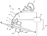
また、図9は、本発明の実施例2に係る電動パワーステアリング装置1bを示す概略構成図であり、実施例1と同一の部材には同一の符号を付して、その説明を省略する。同図において、電動パワーステアリング装置1bのステアリング系は、ステアリングコラム3に設けられた電動モータ11Cの駆動力を、クラッチ機構26および減速機構12Cを介して操舵補助されるとともに、ステアリングギア部(ピニオン部)9に設けられた電動モータ11Dの駆動力を減速機構12Dを介して操舵補助されるようになっている。これにより、実施例1と同様の作用効果を得られることはもとより、設置スペースにあまり余裕がないステアリングコラム3に設けられた電動モータ11Cの容量を小さくすることができる。この結果、ステアリングコラム部の設置スペースに制限のある車種に対しても対応することができる。
FIG. 9 is a schematic configuration diagram showing an electric power steering apparatus 1b according to the second embodiment of the present invention. The same members as those in the first embodiment are denoted by the same reference numerals, and the description thereof is omitted. In the figure, the steering system of the electric power steering device 1b is assisted by steering the driving force of the electric motor 11C provided in the
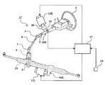
また、図10は、本発明の実施例3に係る電動パワーステアリング装置1cを示す概略構成図であり、実施例1と同一の部材には同一の符号を付して、その説明を省略する。同図において、電動パワーステアリング装置1cのステアリング系は、ステアリングギア部(ピニオン部)9に設けられた電動モータ11Eの駆動力を、クラッチ機構26および減速機構12Eを介して操舵補助されるとともに、同じくステアリングギア部(ピニオン部)9に設けられた電動モータ11Fの駆動力を減速機構12Fを介して操舵補助されるようになっている。これにより、実施例1と同様の作用効果を得られることはもとより、設置スペースにあまり余裕がないステアリングコラム部には電動モータを配さずに、比較的設置スペースに余裕があるピニオン部に2台の電動モータ11E,11Fを配すため、ステアリングコラム部の設置スペースに制限のある車種に対しても対応することができる。
FIG. 10 is a schematic configuration diagram showing an electric power steering apparatus 1c according to the third embodiment of the present invention. The same members as those in the first embodiment are denoted by the same reference numerals, and the description thereof is omitted. In the figure, the steering system of the electric power steering device 1c is assisted by steering the driving force of the
また、図11は、本発明の実施例4に係る電動パワーステアリング装置1dを示す概略構成図であり、実施例1と同一の部材には同一の符号を付して、その説明を省略する。同図において、電動パワーステアリング装置1dのステアリング系のラック軸10は、ステアリングギア部(ピニオン部)9に設けられた電動モータ11Gの駆動力を、クラッチ機構26および減速機構12Gを介してピニオン軸(第1ピニオン軸)8から操舵補助されるとともに、他の転舵輪側(図11右側)で、第2ピニオン軸8´に係合し、該第2ピニオン軸8´は、減速機構12Hを介して電動モータ11Hに連結され、該電動モータ11Hによって操舵補助されるようになっている。これにより、実施例1と同様の作用効果を得られることはもとより、設置スペースにあまり余裕がないステアリングコラム部には電動モータを配さずに、比較的設置スペースに余裕があるピニオン部およびラック部に電動モータ11G,11Hを配すため、ステアリングコラム部の設置スペースに制限のある車種に対しても対応することができ、且つ第1ピニオン8の負荷を軽減することができ、高出力化を図ることができる。
FIG. 11 is a schematic configuration diagram showing an electric power steering apparatus 1d according to the fourth embodiment of the present invention. The same members as those of the first embodiment are denoted by the same reference numerals, and the description thereof is omitted. In the figure, the
また、図12は、本発明の実施例5に係る電動パワーステアリング装置1eを示す概略構成図であり、実施例1と同一の部材には同一の符号を付して、その説明を省略する。同図において、電動パワーステアリング装置1eのステアリング系のラック軸10は、ステアリングギア部(ピニオン部)9に設けられた電動モータ11Iの駆動力を、クラッチ機構26および減速機構12Iを介してピニオン軸(第1ピニオン軸)8から操舵補助されるとともに、他の転舵輪側(図12右側)で、ボールスクリューに係合する減速機構(ボールスクリュー伝達機構)50Jを介して電動モータ11Jに連結され、該電動モータ11Jによって操舵補助されるようになっている。
FIG. 12 is a schematic configuration diagram showing an electric power steering apparatus 1e according to the fifth embodiment of the present invention. The same members as those in the first embodiment are denoted by the same reference numerals, and the description thereof is omitted. In the figure, the
図13は、ラック&ピニオン機構の縦断面図である。同図において、符号52で示した部材は、ラック&ピニオンハウジングであり、ラック&ピニオン機構を構成するラック軸10とピニオン軸8を保持している。ラック軸10は、ピニオン軸8のピニオンに噛合するラック53を図中左側に有する。
FIG. 13 is a longitudinal sectional view of the rack and pinion mechanism. In the figure, a member denoted by reference numeral 52 is a rack and pinion housing, and holds a
ボールスクリュー伝達機構50Jは、ラック&ピニオンハウジング52の図13右端にボルト締めされたギアハウジング54と、該ギアハウジング54にボルト締めされ、ラック&ピニオンハウジング52やギアハウジング54とともにステアリングギアケースを構成するボールスクリューハウジング55とを外郭としている。
The ball
ギアハウジング54は、その下部に電動モータ11Jを備え、該電動モータ11Jの駆動軸56に固着されたドライブギア57と、該ドライブギア57に噛合するドリブンギア58とを収納している。図中の符号59は、ドライブギア57を回転自在に支持する軸受を示し、符号60は、ドリブンギア58を回転自在に支持する軸受を示している。
The
ボールスクリューハウジング55には、ボールナット61が複列アンギュラ玉軸受62を介して回転自在に保持されている。また、ラック軸10には、雄ネジ溝63が形成される一方、ボールナット61には雌ネジ溝64が形成され、雄ネジ溝63と雌ネジ溝64との間には循環ボールとして多数個の鋼球65が介装されている。
A
ドリブンギア58は、軸心にラック軸10が挿通される中空部66を有し、該中空部66の図中右端で、ドリブンギア58とボールナット61とが、比較的緩く嵌合しており、自由に相対摺動できるようになっている。
The driven
電動モータ11Jは、ECU17からの信号に基づき、正逆いずれかの方向に回転し、ドライブギア57およびドリブンギア58を介して、その回転がドリブンギア58にスプライン係合したボールナット61に減速して伝達される。ボールナット61が回転すると、その雌ネジ溝64に係合した鋼球65を介してラック軸10の雄ネジ溝63にスラスト力が作用し、これにより操舵補助が実現される。
The
このように、本実施例では、ピニオン部9に設けられた電動モータ11Iの駆動力を、クラッチ機構26および減速機構12Iを介して操舵補助するとともに、電動モータ11Jの駆動力を、ラック軸10のボールスクリューに係合するボールスクリュー伝達機構50Jを介して操舵補助するようにした。これにより、実施例1と同様の作用効果を得られることはもとより、設置スペースにあまり余裕がないステアリングコラム3には電動モータを配さずに、比較的設置スペースに余裕があるピニオン部およびボールスクリュー部に電動モータ11I,11Jを配すため、ステアリングコラム部の設置スペースに制限のある車種に対しても対応することができる。
As described above, in this embodiment, the driving force of the electric motor 11I provided in the pinion unit 9 is assisted by the steering via the
また、電動モータ11Jの駆動力を、耐久性の高いボールスクリューを採用したボールスクリュー伝達機構50Jを介してラック軸に伝達することにより、第1ピニオンの負荷を軽減することができるとともに、電動モータ11Jの高出力化を図ることができる。
In addition, the load of the first pinion can be reduced by transmitting the driving force of the
また、図14は、本発明の実施例6に係る電動パワーステアリング装置1fを示す概略構成図であり、実施例1および実施例5と同一の部材には同一の符号を付して、その説明を省略する。同図において、電動パワーステアリング装置1fのステアリング系は、ステアリングコラム3に設けられた電動モータ11Kの駆動力を、クラッチ機構26および減速機構26を介して操舵補助されるとともに、電動モータ11Lの駆動力を、ラック軸10のボールスクリューに係合する減速機構(ボールスクリュー伝達機構)50Lを介して操舵補助されるようになっている。これにより、実施例1と同様の作用効果を得られることはもとより、設置スペースにあまり余裕がないステアリングコラム3に設けられた電動モータ11Kの容量を小さくすることができ、ステアリングコラム部の設置スペースに制限のある車種に対しても対応することができる。
FIG. 14 is a schematic configuration diagram showing an electric power steering apparatus 1f according to Embodiment 6 of the present invention. The same members as those in Embodiments 1 and 5 are denoted by the same reference numerals, and description thereof is provided. Is omitted. In the figure, the steering system of the electric power steering apparatus 1f is assisted by the driving force of the electric motor 11K provided in the
また、電動モータ11Lの駆動力を、耐久性の高いボールスクリューを採用したボールスクリュー伝達機構50Lを介してラック軸に伝達することにより、ピニオン軸8の負荷を軽減することができるとともに、電動モータ11Lの高出力化を図ることができる。
Further, by transmitting the driving force of the electric motor 11L to the rack shaft via a ball
以上、本発明を具体的に説明してきたが、本発明はそれに限定されるものではなく、その趣旨を逸脱しない範囲で種々変更可能である。 Although the present invention has been specifically described above, the present invention is not limited thereto, and various modifications can be made without departing from the spirit of the present invention.
1 電動パワーステアリング装置
3 ステアリングコラム
8 ピニオン軸
9 ステアリングギア部(ピニオン部)
10 ラック軸
11 電動モータ
12 減速機構
17 制御手段(ECU)
26 クラッチ機構
50 減速機構(ボールスクリュー伝達機構)
DESCRIPTION OF SYMBOLS 1 Electric
DESCRIPTION OF
26 Clutch mechanism 50 Reduction mechanism (ball screw transmission mechanism)
Claims (11)
該電動モータの動作を負荷状態に応じて個別に制御するための制御手段とを備え、
少なくとも一つの前記電動モータは、逆作動のトルク伝達が空転するクラッチ機構を備えたことを特徴とする電動パワーステアリング装置。 A plurality of electric motors for assisting in steering the steering system;
Control means for individually controlling the operation of the electric motor according to the load state,
The electric power steering apparatus according to claim 1, wherein at least one of the electric motors includes a clutch mechanism that idles torque transmission in reverse.
Priority Applications (1)
| Application Number | Priority Date | Filing Date | Title |
|---|---|---|---|
| JP2004115729A JP2005297718A (en) | 2004-04-09 | 2004-04-09 | Power steering device |
Applications Claiming Priority (1)
| Application Number | Priority Date | Filing Date | Title |
|---|---|---|---|
| JP2004115729A JP2005297718A (en) | 2004-04-09 | 2004-04-09 | Power steering device |
Publications (1)
| Publication Number | Publication Date |
|---|---|
| JP2005297718A true JP2005297718A (en) | 2005-10-27 |
Family
ID=35329795
Family Applications (1)
| Application Number | Title | Priority Date | Filing Date |
|---|---|---|---|
| JP2004115729A Pending JP2005297718A (en) | 2004-04-09 | 2004-04-09 | Power steering device |
Country Status (1)
| Country | Link |
|---|---|
| JP (1) | JP2005297718A (en) |
Cited By (2)
| Publication number | Priority date | Publication date | Assignee | Title |
|---|---|---|---|---|
| WO2008056771A1 (en) * | 2006-11-10 | 2008-05-15 | Jtekt Corporation | Electric power steering device |
| JP2013208929A (en) * | 2012-03-30 | 2013-10-10 | Kyb Co Ltd | Electric power steering device |
-
2004
- 2004-04-09 JP JP2004115729A patent/JP2005297718A/en active Pending
Cited By (3)
| Publication number | Priority date | Publication date | Assignee | Title |
|---|---|---|---|---|
| WO2008056771A1 (en) * | 2006-11-10 | 2008-05-15 | Jtekt Corporation | Electric power steering device |
| US8116946B2 (en) | 2006-11-10 | 2012-02-14 | Jtekt Corporation | Electric power steering device |
| JP2013208929A (en) * | 2012-03-30 | 2013-10-10 | Kyb Co Ltd | Electric power steering device |
Similar Documents
| Publication | Publication Date | Title |
|---|---|---|
| US5327986A (en) | Electric motor drive-type power steering system | |
| US8327971B2 (en) | Reducer of electric power steering apparatus | |
| US5836419A (en) | Rack and pinion electric power steering system with unitized construction for removable mounting | |
| KR20130104000A (en) | Electric power steering apparatus for vehicle | |
| JP3888607B2 (en) | Electric power steering device | |
| EP1445171A2 (en) | Automotive steering system | |
| US20090260468A1 (en) | Steering device and movement converting device used therefor | |
| JPH08258728A (en) | Electric power steering device | |
| JP2006111133A (en) | Electric power steering device | |
| JP2005247214A (en) | Electric power steering device | |
| CN114348103A (en) | Steer-by-wire type steering device | |
| JP4491716B2 (en) | Electric power steering device | |
| JP2006027321A (en) | Electric power-steering device | |
| JP5207054B2 (en) | Variable stiffness stabilizer | |
| US20080035413A1 (en) | Electric Power Steering Device | |
| JP2005297718A (en) | Power steering device | |
| JP4238577B2 (en) | Electric power steering device | |
| JP2002087295A (en) | Electric power steering device | |
| US20230052990A1 (en) | Electric power steering apparatus | |
| RU2721452C1 (en) | Power steering amplifier with electric drive | |
| JPH0714109Y2 (en) | Power steering device | |
| JP4085867B2 (en) | Worm support device and electric power steering device | |
| JPH02220969A (en) | Electric power steering device | |
| JP2830992B2 (en) | Electric power steering device | |
| JP2009180322A (en) | Steering device with telescopic shaft and telescopic shaft |
Legal Events
| Date | Code | Title | Description |
|---|---|---|---|
| A711 | Notification of change in applicant |
Free format text: JAPANESE INTERMEDIATE CODE: A711 Effective date: 20050711 |