JP2005297613A - Electric power steering device - Google Patents
Electric power steering device Download PDFInfo
- Publication number
- JP2005297613A JP2005297613A JP2004112427A JP2004112427A JP2005297613A JP 2005297613 A JP2005297613 A JP 2005297613A JP 2004112427 A JP2004112427 A JP 2004112427A JP 2004112427 A JP2004112427 A JP 2004112427A JP 2005297613 A JP2005297613 A JP 2005297613A
- Authority
- JP
- Japan
- Prior art keywords
- drive gear
- output shaft
- joint
- electric motor
- electric power
- Prior art date
- Legal status (The legal status is an assumption and is not a legal conclusion. Google has not performed a legal analysis and makes no representation as to the accuracy of the status listed.)
- Pending
Links
- 238000005096 rolling process Methods 0.000 claims abstract description 37
- 230000005540 biological transmission Effects 0.000 claims abstract description 33
- 230000004308 accommodation Effects 0.000 claims description 8
- 238000005452 bending Methods 0.000 description 15
- 238000000465 moulding Methods 0.000 description 13
- 230000036316 preload Effects 0.000 description 12
- 238000006243 chemical reaction Methods 0.000 description 9
- 230000001629 suppression Effects 0.000 description 9
- 229920003002 synthetic resin Polymers 0.000 description 7
- 239000000057 synthetic resin Substances 0.000 description 7
- 229920003051 synthetic elastomer Polymers 0.000 description 5
- 239000005061 synthetic rubber Substances 0.000 description 5
- 239000013013 elastic material Substances 0.000 description 4
- 239000000463 material Substances 0.000 description 4
- 230000002093 peripheral effect Effects 0.000 description 4
- 238000006073 displacement reaction Methods 0.000 description 3
- 239000012209 synthetic fiber Substances 0.000 description 3
- 229920002994 synthetic fiber Polymers 0.000 description 3
- XEEYBQQBJWHFJM-UHFFFAOYSA-N Iron Chemical compound [Fe] XEEYBQQBJWHFJM-UHFFFAOYSA-N 0.000 description 2
- 230000006835 compression Effects 0.000 description 2
- 238000007906 compression Methods 0.000 description 2
- 229910052751 metal Inorganic materials 0.000 description 2
- 239000002184 metal Substances 0.000 description 2
- 230000002159 abnormal effect Effects 0.000 description 1
- 229910052782 aluminium Inorganic materials 0.000 description 1
- XAGFODPZIPBFFR-UHFFFAOYSA-N aluminium Chemical compound [Al] XAGFODPZIPBFFR-UHFFFAOYSA-N 0.000 description 1
- 230000008602 contraction Effects 0.000 description 1
- 230000007423 decrease Effects 0.000 description 1
- 230000000694 effects Effects 0.000 description 1
- 229910052742 iron Inorganic materials 0.000 description 1
- 238000000034 method Methods 0.000 description 1
- 230000007935 neutral effect Effects 0.000 description 1
- 230000003014 reinforcing effect Effects 0.000 description 1
- 230000000754 repressing effect Effects 0.000 description 1
- 238000004073 vulcanization Methods 0.000 description 1
Images

Landscapes
- Gears, Cams (AREA)
- Power Steering Mechanism (AREA)
- Gear Transmission (AREA)
Abstract
Description
本発明は操舵補助力の発生源として電動モータを用いてなる電動パワーステアリング装置に関する。 The present invention relates to an electric power steering apparatus using an electric motor as a generation source of a steering assist force.
車両用の電動パワーステアリング装置は、操舵補助用の電動モータ及び該電動モータの回転力を操舵手段に伝える減速歯車機構を備えており、ステアリングホイールの操作に応じた操舵手段の動作を前記電動モータの回転により補助し、舵取りのための運転者の労力負担を軽減するように構成されている。 An electric power steering apparatus for a vehicle includes an electric motor for assisting steering and a reduction gear mechanism that transmits a rotational force of the electric motor to a steering means, and the operation of the steering means according to an operation of a steering wheel is controlled by the electric motor. It is configured to assist with the rotation of the vehicle and reduce the labor burden on the driver for steering.
減速歯車機構は前記電動モータの出力軸に継体により連動連結される駆動歯車と、該駆動歯車に噛合し、前記操舵手段に繋がる従動歯車とを備えている。前記継体は出力軸及び駆動歯車にセレーション嵌合されたセレーション筒体が用いられており、出力軸の回転力をセレーション筒体から駆動歯車に伝動するようにしてある(例えば、特許文献1。)。また、駆動歯車は継体に対し反電動モータ側へ離隔した部分が転がり軸受を介してハウジング内に回転自在に支持されている。 The reduction gear mechanism includes a drive gear that is interlocked and connected to the output shaft of the electric motor by a joint, and a driven gear that meshes with the drive gear and is connected to the steering means. As the joint, a serration cylinder that is serrated and fitted to an output shaft and a drive gear is used, and the rotational force of the output shaft is transmitted from the serration cylinder to the drive gear (for example, Patent Document 1). . Further, the drive gear is rotatably supported in the housing via a rolling bearing at a portion separated from the joint toward the counter-electric motor side.
また、電動モータ側が転がり軸受により支持された駆動歯車の反電動モータ側を駆動歯車及び従動歯車の回転中心間距離が短くなる方向へ弾圧する弾圧手段を備え、該弾圧手段により駆動歯車及び従動歯車の噛合部に予圧を加え、噛合部のバックラッシュ量を少なくして転舵時のバックラッシュによる歯打ち音を低減するように構成された電動パワーステアリング装置も知られている(例えば、特許文献1。)。
ところが、特許文献1のようにセレーション筒体からなる継体を備える電動パワーステアリング装置にあっては、セレーション筒体、出力軸及び駆動歯車のセレーション部の寸法誤差等により出力軸の軸線に対して駆動歯車が偏心又は偏角した場合、前記噛合部のバックラッシュ量が多くなるため、前記継体部分に適宜のラジアル隙間が必要である。しかしながら、ラジアル隙間が大きくなると継体部分にガタつきが発生することになり、ガタつきによる異音が車室に洩れ、運転者に不快感を与えることになると言う問題がある。 However, in the electric power steering apparatus having a joint composed of a serration cylinder as in Patent Document 1, the electric power steering apparatus is driven with respect to the axis of the output shaft due to a dimensional error of the serration cylinder, the output shaft, and the serration portion of the drive gear. When the gear is decentered or deviated, the backlash amount of the meshing portion is increased, so that an appropriate radial gap is required in the joint portion. However, when the radial gap increases, there is a problem that rattling occurs in the joint portion, and abnormal noise due to the rattling leaks into the passenger compartment, which causes discomfort to the driver.
また、転がり軸受には複数の転動体を介して嵌合された内輪及び外輪間にラジアル隙間があり、このラジアル隙間によって駆動歯車が軸線方向へガタつき、このガタつきによって発生する異音が車室の内部に洩れることになり、運転者に不快感を与えることになるため、前記ラジアル隙間を低減する必要がある。 In addition, the rolling bearing has a radial gap between the inner ring and the outer ring fitted via a plurality of rolling elements, and the drive gear is rattled in the axial direction due to the radial gap. Since this leaks into the interior of the room and causes discomfort to the driver, it is necessary to reduce the radial gap.
このラジアル隙間を低減する手段として、転がり軸受の外輪の一側に当接するねじ環を設けるか、又は駆動歯車を軸線方向へ弾圧するばね体を設けることにより、転がり軸受の外輪及び内輪を軸線方向へ相対移動させてラジアル隙間をなくするように構成されているが、何れの方法にあっても、特別の部材が必要であり、構造が複雑になる。 As means for reducing this radial clearance, a screw ring that contacts one side of the outer ring of the rolling bearing is provided, or a spring body that elastically presses the drive gear in the axial direction is provided, so that the outer ring and inner ring of the rolling bearing are axially arranged. However, in any method, a special member is required and the structure becomes complicated.
また、噛合部に予圧を加えるように構成された場合、駆動歯車は出力軸の軸線に対して偏角することになり、この偏角を許容すべく前記継体部分のラジアル隙間が大きくなるため、転がり軸受のラジアル隙間が大きくなるように構成されている。従って、継体部分及び転がり軸受部分にガタつきが発生し易くなる。 Further, when configured to apply preload to the meshing portion, the drive gear is deviated with respect to the axis of the output shaft, and the radial gap of the joint portion is increased to allow this declination, The radial clearance of the rolling bearing is configured to be large. Therefore, rattling is likely to occur in the joint portion and the rolling bearing portion.
本発明は斯る事情に鑑みてなされたものであり、主たる目的は出力軸に対して駆動歯車が偏心又は偏角している場合においても、継体部分でのラジアル隙間を低減でき、しかも、駆動歯車を支持する転がり軸受等の隙間に影響されることなく駆動歯車の軸線方向へのガタつきを低減できる電動パワーステアリング装置を提供することにある。また、他の目的は前記噛合部に予圧を加えるように構成された場合、駆動歯車の前記出力軸との連動連結部分のラジアル隙間を大きくすることなく、駆動歯車の偏角量を多くすることができる電動パワーステアリング装置を提供することにある。また、他の目的は駆動歯車の偏角量を確保でき、しかも噛合反力による音鳴りを低減できる電動パワーステアリング装置を提供することにある。 The present invention has been made in view of such circumstances, and the main object is to reduce the radial gap in the joint portion even when the drive gear is decentered or deviated with respect to the output shaft, and the drive It is an object of the present invention to provide an electric power steering device that can reduce backlash in the axial direction of a drive gear without being affected by a gap of a rolling bearing or the like that supports the gear. Another object of the present invention is to increase the deflection angle of the drive gear without increasing the radial clearance of the interlocking connection portion of the drive gear with the output shaft when the preload is applied to the meshing portion. An object of the present invention is to provide an electric power steering apparatus capable of Another object of the present invention is to provide an electric power steering device that can secure a deviation amount of a drive gear and can reduce noise caused by a meshing reaction force.
第1発明に係る電動パワーステアリング装置は、電動モータの出力軸に継体により連動連結される駆動歯車と、該駆動歯車に噛合し、操舵手段に繋がる従動歯車とを備え、前記電動モータの回転によって操舵補助するようにした電動パワーステアリング装置において、前記継体は可撓性を有し、回転中心軸に対してラジアル方向外側部に連動連結部を、また回転中心軸のアキシャル方向一側又は両側に可撓凸部をそれぞれ有することを特徴とする。 An electric power steering apparatus according to a first aspect of the present invention includes a drive gear that is interlocked and connected to an output shaft of an electric motor by a joint, and a driven gear that meshes with the drive gear and is connected to a steering means. In the electric power steering apparatus configured to assist steering, the joint is flexible, and has an interlocking connection portion on a radially outer side with respect to the rotation center axis and on one side or both sides of the rotation center axis in the axial direction. It has a flexible convex part, respectively.
第1発明にあっては、可撓性を有する継体が駆動歯車及び出力軸を連動連結しているため、出力軸に対して駆動歯車が偏心又は偏角している場合、継体を撓ませることができ、継体部分でのラジアル隙間を低減できる。また、継体の回転中心軸部には可撓凸部が設けられており、駆動歯車が出力軸に連動連結される場合、出力軸及び駆動歯車の一方又は両方の端面を可撓凸部に当接させ、該可撓凸部を撓ませることができるため、この可撓凸部の弾性復元力を駆動歯車に加えることができ、該駆動歯車を軸線方向に移動させることができる。従って、駆動歯車を支持する軸受等の隙間に影響されることなく駆動歯車の軸線方向へのガタつきを低減でき、このガタつきによる音鳴りをなくし得る。また、可撓凸部は継体の回転中心軸部に設けられているため、継体が撓む場合においても可撓凸部の弾性復元力を安定させることができる。 In the first invention, since the flexible joint interlocks the drive gear and the output shaft, the joint is bent when the drive gear is eccentric or deviated with respect to the output shaft. And the radial gap in the joint portion can be reduced. In addition, a flexible convex portion is provided on the rotation center shaft portion of the joint, and when the drive gear is linked to the output shaft, one or both end faces of the output shaft and the drive gear are abutted against the flexible convex portion. Since the flexible convex portion can be bent and brought into contact, the elastic restoring force of the flexible convex portion can be applied to the drive gear, and the drive gear can be moved in the axial direction. Therefore, the play in the axial direction of the drive gear can be reduced without being affected by the gap of the bearing or the like that supports the drive gear, and the noise caused by this play can be eliminated. Moreover, since the flexible convex part is provided in the rotation center shaft part of the joint, even when the joint is bent, the elastic restoring force of the flexible convex part can be stabilized.
第2発明に係る電動パワーステアリング装置は、前記出力軸及び前記駆動歯車は複数の偏心ピンを有しており、前記継体は前記偏心ピンのそれぞれが内嵌された伝動孔を有することを特徴とする。 In the electric power steering apparatus according to a second aspect of the invention, the output shaft and the drive gear have a plurality of eccentric pins, and the joint has a transmission hole in which each of the eccentric pins is fitted. To do.
第2発明にあっては、出力軸の回転力を継体の回転中心軸に対してラジアル方向外側部から偏心ピンを経て駆動歯車に伝動するため、出力軸に対して駆動歯車が偏心又は偏角している場合、継体を出力軸の軸線と交差する方向へ撓ませることができ、継体から駆動歯車に加わるラジアル方向の弾性復元力を低減できる。従って、駆動歯車を支持する軸受への負担を低減でき、駆動歯車の回転性を維持することができる。また、駆動歯車及び従動歯車の噛合部に予圧を加えるように構成された場合、弾圧手段が噛合部に加える予圧の減少を少なくすることができ、噛合部のバックラッシュ量が少ない状態を維持することができる。 In the second aspect of the invention, the rotational force of the output shaft is transmitted from the radially outer portion to the drive gear via the eccentric pin with respect to the rotation center axis of the joint, so that the drive gear is eccentric or deviated with respect to the output shaft. In this case, the joint can be bent in a direction intersecting the axis of the output shaft, and the radial elastic restoring force applied to the drive gear from the joint can be reduced. Therefore, the load on the bearing that supports the drive gear can be reduced, and the rotation of the drive gear can be maintained. Further, when the preload is applied to the meshing portion of the drive gear and the driven gear, the reduction of the preload applied by the elastic pressure means to the meshing portion can be reduced, and the state where the backlash amount of the meshing portion is small is maintained. be able to.
第3発明に係る電動パワーステアリング装置は、前記駆動歯車及び従動歯車の回転中心間距離が短くなる方向への移動を可能に前記駆動歯車の反電動モータ側を支持する軸受部材と、該軸受部材を収容する収容孔と、前記軸受部材を前記回転中心間距離が短くなる方向へ弾圧する弾圧手段と、前記軸受部材又は前記収容孔に保持された弾性筒体とを備えることを特徴とする。 According to a third aspect of the present invention, there is provided an electric power steering apparatus, comprising: a bearing member that supports a side of the drive gear that is opposite to the electric motor so that the drive gear and the driven gear can move in a direction in which the distance between the rotation centers of the drive gear and the driven gear is short; And a resilient pressure member for resiliently compressing the bearing member in a direction in which the distance between the rotation centers is shortened, and an elastic cylinder held in the bearing member or the accommodation hole.
第3発明にあっては、駆動歯車及び従動歯車の噛合部に予圧を加えるように構成された電動パワーステアリング装置において、前記噛合部に噛合反力が発生し、該噛合反力により前記回転中心間距離が長くなる方向へ駆動歯車が移動する場合、軸受部材が弾性筒体を介して収容孔に接触し、駆動歯車の移動を制限することになるが、軸受部材が弾性筒体を介して収容孔に接触するため、軸受部材と収容孔との接触面積を多くでき、弾性筒体の硬度を比較的低くでき、噛合反力による音鳴りを低減できる。 In the third aspect of the invention, in the electric power steering apparatus configured to apply preload to the meshing portion of the drive gear and the driven gear, a meshing reaction force is generated in the meshing portion, and the rotation center is generated by the meshing reaction force. When the drive gear moves in the direction in which the distance increases, the bearing member comes into contact with the receiving hole via the elastic cylinder and restricts the movement of the drive gear. However, the bearing member moves via the elastic cylinder. Since it contacts the accommodation hole, the contact area between the bearing member and the accommodation hole can be increased, the hardness of the elastic cylinder can be relatively lowered, and the noise caused by the meshing reaction force can be reduced.
第4発明に係る電動パワーステアリング装置は、電動モータの出力軸に連動連結される駆動歯車と、該駆動歯車の電動モータ側を支持部材に回転自在に支持する転がり軸受と、前記駆動歯車に噛合し、操舵手段に繋がる従動歯車と、前記駆動歯車及び従動歯車の回転中心間距離が短くなる方向へ前記駆動歯車の反電動モータ側を弾圧する弾圧手段とを備え、前記電動モータの回転によって操舵補助するようにした電動パワーステアリング装置において、前記転がり軸受の内側に弾性体が配置されており、該弾性体に前記出力軸及び前記駆動歯車が連動連結されていることを特徴とする。 According to a fourth aspect of the present invention, there is provided an electric power steering apparatus according to a fourth aspect of the present invention, wherein a driving gear interlocked with the output shaft of the electric motor, a rolling bearing that rotatably supports the electric motor side of the driving gear on a support member, and the driving gear mesh with the driving gear. And a driven gear connected to the steering means, and a pressing means for pressing the non-electric motor side of the drive gear in a direction in which the distance between the rotation centers of the drive gear and the driven gear is shortened, and is steered by the rotation of the electric motor. In the assisting electric power steering apparatus, an elastic body is disposed inside the rolling bearing, and the output shaft and the driving gear are interlocked and connected to the elastic body.
第4発明にあっては、駆動歯車を支持する転がり軸受の内側に出力軸及び駆動歯車の連動連結部があるため、駆動歯車を従動歯車に向けて弾圧する弾圧手段によってバックラッシュ量を調整する場合、転がり軸受への支持部を支点として偏角する駆動歯車の連動連結部でのラジアル隙間の量を低減でき、しかも、バックラッシュ量の調整代を充分に確保することができる。 In the fourth aspect of the invention, since the interlocking connecting portion of the output shaft and the drive gear is provided inside the rolling bearing that supports the drive gear, the backlash amount is adjusted by the compression means that compresses the drive gear toward the driven gear. In this case, it is possible to reduce the amount of radial clearance at the interlocking connecting portion of the drive gear that is declined with the support portion for the rolling bearing as a fulcrum, and it is possible to secure a sufficient backlash adjustment amount.
第1発明によれば、出力軸に対して駆動歯車が偏心又は偏角している場合においても、継体部分でのラジアル隙間を低減でき、しかも、駆動歯車を支持する軸受等の隙間に影響されることなく駆動歯車の軸線方向へのガタつきを低減でき、さらに継体が撓む場合においても可撓凸部の弾性復元力を安定させることができる。 According to the first invention, even when the drive gear is decentered or deviated with respect to the output shaft, the radial gap at the joint portion can be reduced, and it is also affected by the gap of the bearing or the like that supports the drive gear. The backlash of the drive gear in the axial direction can be reduced, and even when the joint is bent, the elastic restoring force of the flexible convex portion can be stabilized.
第2発明によれば、継体から駆動歯車に加わるラジアル方向の弾性復元力を低減できるので、駆動歯車を支持する軸受への負担を低減でき、駆動歯車の回転性を維持することができる。 According to the second aspect of the invention, since the radial elastic restoring force applied to the drive gear from the joint can be reduced, the load on the bearing that supports the drive gear can be reduced, and the rotation of the drive gear can be maintained.
第3発明によれば、噛合反力により回転中心間距離が長くなる方向へ駆動歯車が移動する場合、軸受部材と収容孔との接触面積を多くでき、弾性筒体の硬度を比較的低くでき、噛合反力による音鳴りを低減できる。 According to the third aspect of the present invention, when the drive gear moves in a direction in which the distance between the rotation centers becomes longer due to the meshing reaction force, the contact area between the bearing member and the accommodation hole can be increased, and the hardness of the elastic cylindrical body can be relatively lowered. , The noise due to the meshing reaction force can be reduced.
第4発明によれば、転がり軸受への支持部を支点として偏角する駆動歯車の連動連結部でのラジアル隙間の量を低減でき、しかも、バックラッシュ量の調整代を充分に確保することができる。 According to the fourth invention, it is possible to reduce the amount of radial clearance at the interlocking connecting portion of the drive gear that is deviated with the support portion for the rolling bearing as a fulcrum, and to sufficiently secure the backlash amount adjustment allowance. it can.
以下本発明をその実施の形態を示す図面に基づいて詳述する。
実施の形態1
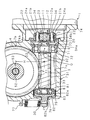
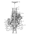
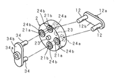
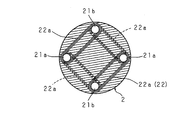
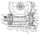
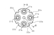
図1は本発明に係る電動パワーステアリング装置の構成を示す減速歯車機構部分の拡大断面図、図2は電動パワーステアリング装置の全体構成を示す断面図、図3は要部の分解した拡大斜視図、図4は要部の断面図、図5は継体の断面図である。
Hereinafter, the present invention will be described in detail with reference to the drawings illustrating embodiments thereof.
Embodiment 1
1 is an enlarged sectional view of a reduction gear mechanism portion showing the configuration of an electric power steering device according to the present invention, FIG. 2 is a sectional view showing the entire configuration of the electric power steering device, and FIG. 4 is a cross-sectional view of the main part, and FIG. 5 is a cross-sectional view of the joint.
電動パワーステアリング装置は、操舵補助用の電動モータ1と、該電動モータ1の出力軸11に継体2を介して連動連結される駆動歯車としてのウォーム3及び該ウォーム3に噛合する従動歯車としてのウォームホイール4を有する減速歯車機構Aと、ウォームホイール4を支持した回転軸(後記する)を有し、ウォームホイール4に繋がる操舵手段5とを備えている。
The electric power steering apparatus includes an electric motor 1 for assisting steering, a
この操舵手段5は、一端部が舵取りのためのステアリングホイールBに繋がり、他端部に筒部51aを有する第1の操舵軸51と、筒部51a内に挿入されてその一端部が第1の操舵軸51の筒部51aに連結され、ステアリングホイールBに加わる操舵トルクの作用によって捩れるトーションバー52と、該トーションバー52の他端部に連結され、ウォームホイール4に繋がる回転軸としての第2の操舵軸53とを備え、該第2の操舵軸53がユニバーサルジョイント及び中間軸を介して例えばラックピニオン式の舵取機構(不図示)に繋がる。
The steering means 5 has one end connected to a steering wheel B for steering, a
減速歯車機構Aのウォーム3は中央部に歯部31を有し、両端に軸部32,33を有する金属製の軸部材からなり、一方の軸部32が転がり軸受6を介して支持部材7に回転自在に収容支持された状態で出力軸11に連動連結され、他方の軸部33が軸受部材8を介して支持部材7に収容支持されている。尚、軸部32は転がり軸受6の内輪に圧入されている。
The
ウォームホイール4は外周部に歯を有し、中心部に嵌合孔を有しており、第2の操舵軸53の途中に嵌合固定されている。
The
支持部材7はウォーム3を収容し、該ウォーム3の軸部31,32を、転がり軸受6及び軸受部材8を介して回転自在に支持した第1収容部7aと、ウォームホイール4を収容し、該ウォームホイール4を第2の操舵軸53及び該第2の操舵軸53に嵌合された2つの転がり軸受9,10を介して支持した第2収容部7bとを有する。
The
第1収容部7aはウォーム3の軸線方向に長くなっており、その長手方向一端部には転がり軸受6を遊嵌合により支持する支持孔71と、該支持孔71に連なる段部72及びねじ孔73と、モータ取付部74が設けられており、転がり軸受6の外輪に接触して外輪を段部72との間で固定するためのねじ環20がねじ孔73に螺着されている。また、モータ取付部74に電動モータ1が複数本のボルトにより取付けられている。
The first
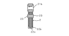
電動モータ1の出力軸11及びウォーム3の軸部32は、出力軸11に突設された2つの偏心ピン12,12と、軸部32に突設された2つの偏心ピン34,34と、縁部に各偏心ピン12,34が内嵌された伝動部としての伝動孔21a,21a、21b,21bを有し、板厚方向が出力軸11の軸線方向となり、可撓性を有する板状の継体2とにより連動連結されている。
The
偏心ピン12,12は、出力軸11の端部に外嵌(スプライン嵌合)された筒部12aからラジアル方向へ延出されたアーム12bの端部に一体に設けられている。偏心ピン34,34は、軸部32に外嵌(スプライン嵌合)された筒部34aからラジアル方向へ延出されたアーム34bの端部に一体に設けられている。
The eccentric pins 12 and 12 are integrally provided at the end portion of the
継体2は合成ゴム、合成樹脂等の可撓性を有する弾性材料によって板厚が比較的厚く成形された板状であり、回転中心軸に対してラジアル方向外側部(外周部)に等配された伝動孔21a,21a、21b,21bと、出力軸11の回転方向への撓みを抑制する撓み抑制手段22と、回転中心軸のアキシャル方向両側に成形により一体に突設された可撓凸部23,23とを有する。可撓凸部23,23は先端を平坦面とし、出力軸11の端面及び軸部32の端面と当接することにより高さが低くなるように撓み、この撓みによる弾性復元力がウォーム3に軸線方向への押圧力として加わるようにしてある。また、伝動孔21a,21a、21b,21bの両端部には補強用の環状凸部24a,24bが一体に成形されている。尚、可撓凸部23,23は円柱形としてあるが、その他、円錐台形、半円球であってもよく、その形状は特に制限されない。
The
撓み抑制手段22は、各伝動孔21a,21bに対応する4つの成形用ピンがキャビティに突設された成形用型の前記成形用ピンに合繊糸を長円形に複数回巻き掛けた状態でキャビティに合成ゴム、合成樹脂等の可撓性を有する材料を充填して成形することにより各伝動孔21a,21bの周り、及び各伝動孔21a,21b間を合繊糸22aにより補強し、出力軸11の回転方向へ撓み難いようにしている。この場合、合繊糸22aは成形用ピンに長円形に巻き掛けられているため、板厚方向には撓み抑制効果が小さく、撓み易くなっている。尚、合繊糸22aは一方向で隣り合う2つの成形用ピンにそれぞれ巻き掛けられた後、異方向で隣り合う2つの成形用ピンにそれぞれ巻き掛けられることにより各伝動孔21a,21bの両縁近傍に亘って補強されている(図1、図5参照)。また、巻き掛けられた合繊糸22aの糸間には前記材料が充填され、一体的になっている。
The bending suppression means 22 is a cavity in which a synthetic fiber is wound in an oval shape a plurality of times on the molding pin of a molding die in which four molding pins corresponding to the
第1収容部7aの他端部には、軸受部材8を収容する収容孔75及び該収容孔75の中心部に臨む貫通孔76が設けられており、また、支持部材7の外側には受座77が突設されている。
A receiving
軸受部材8は軸部33に内輪が外嵌された転がり軸受81と、該転がり軸受81の外輪に外嵌固定された軸受ハウジング82とを備えている。軸受ハウジング82は、転がり軸受81に外嵌され、収容孔75に遊嵌された有底の円筒部82aと、該円筒部82aの底部に円筒部82aと同芯的に突設され、貫通孔76に挿入された軸部82bとを有しており、軸部82b及び受座77に引張りコイルバネからなる弾圧部材30が掛設され、ウォーム3を該ウォーム3及びウォームホイール4の回転中心間距離Hが短くなる方向へ弾圧している。
The bearing
円筒部82aの外周部には合成ゴム、合成樹脂等の弾性材料からなる弾性筒体83が保持されている。この弾性筒体83は加硫成形などの成形手段により一体に成形されているが、嵌入、接着等により保持してもよい。また、円筒部82aと弾性筒体83との接触面は平滑面としてあるが、その他、凹凸面又は粗面としてもよい。また、弾性筒体83は収容孔75の内周に装着してもよい。
An
尚、支持部材7内には、トーションバー52の捩れに応じた操舵軸51、53の相対回転変位量によってステアリングホイールBに加わる操舵トルクを検出するトルクセンサ40が内装されており、該トルクセンサ40が検出したトルク等に基づいて電動モータ1が駆動制御されるように構成されている。
The
以上のように構成された電動パワーステアリング装置は、ウォーム3及び電動モータ1を組込む場合、軸部32,33に転がり軸受6,軸受部材8がそれぞれ外嵌され、さらに軸部32に偏心ピン34,34が取付けられたウォーム3を支持部材7の第1収容部7aに挿入し、該ウォーム3側の偏心ピン34,34に継体2を取付け、該継体2の伝動孔21a,21aに出力軸11側の偏心ピン12,12を嵌入しつつ電動モータ1をモータ取付部74に取付ける一方、支持部材7の貫通孔76に挿入された軸部82b及び受座77に弾圧部材(引張りコイルバネ)30の両端部を掛止することにより、ウォーム3を回転中心間距離Hが短くなる方向に弾圧し、噛合部に予圧を加える。
In the electric power steering apparatus configured as described above, when the
予圧が加えられたウォーム3は、転がり軸受6の軸線方向中央近傍位置Oを中心として回転中心間距離Hが短くなる方向に揺動し、継体2は板厚方向に撓む。この場合、弾圧部材30の弾圧力がF方向に加わり、予圧がF1方向に加わり、継体2を撓ませる力がF2方向に加わり、ウォーム3の電動モータ1側端部には継体2の弾性復元力が前記F2と反対方向に加わることになるため、噛合部に加わる予圧は低減されることになる。しかしながら、継体2の回転中心軸に対してラジアル方向外側部に出力軸11側の偏心ピン12,12及びウォーム3側の偏心ピン34,34が連動連結されており、継体2の全体が板厚方向に撓み易いように構成されているため、継体2からウォーム3に加わるラジアル方向の弾性復元力を低減できる。図示した継体2には2つの偏心ピン12,12と、2つの偏心ピン34,34とが周長の1/4間隔で結合されているため、各偏心ピン12,34に対して継体2の全体を板厚方向に撓ませることができる。従って、ウォーム3を支持する転がり軸受6への負担を低減でき、ウォーム3の回転性を維持することができるとともに、弾圧部材30が噛合部に加える予圧の減少を少なくすることができ、噛合部のバックラッシュ量が少ない状態を維持することができる。尚、ウォームホイール4の歯部分が合成樹脂製である場合、周囲温度により歯部分が膨張し、周囲湿度により歯部分が膨潤することになり、また、周囲温度により歯部分が収縮し、周囲湿度により歯部分が収縮することになり、この膨張、収縮によってもウォーム3の偏角は変わることになる。
The
また、以上のように電動モータ1をモータ取付部74に取付けた場合、出力軸11の端面及び軸部32の端面が継体2の可撓凸部23,23に当接し、該可撓凸部23,23を高さが低くなるように撓ませるため、この可撓凸部23,23の撓みによる弾性復元力がウォーム3に軸線方向への押圧力として加わり、ウォーム3を軸線方向に移動させることができる。従って、ウォーム3を支持する転がり軸受6等の隙間に影響されることなくウォーム3の軸線方向へのガタつきを低減でき、このガタつきによる音鳴りをなくし得る。また、可撓凸部23,23は継体2の回転中心軸部に設けられているため、継体2が撓む場合においても可撓凸部23,23の弾性復元力を安定させることができる。
Further, when the electric motor 1 is mounted on the
また、出力軸11の回転力が継体2からウォーム3に伝動される場合、回転方向への撓みが抑制された伝動孔21a,21bから継体2に前記回転力が伝動されるため、継体2の回転方向の剛性を高めることができ、回転方向のトルク伝動機能を高めることができる。また、継体2の耐久性を得ることができる。
Further, when the rotational force of the
また、回転方向のトルクが継体2に加わった場合、該継体2は各伝動孔21a,21bの間の角度θ=90°が増減し、継体2が捩じれて各伝動孔21a,21bの間に周方向の変位が発生するため、電動モータ1が駆動されない操舵領域での操舵負荷を低減することができ、操舵フィーリングを改善することができる。つまり、電動パワーステアリング装置は車両の高速走行時など操舵角が1°程度に小さいときは電動モータ1が駆動されず、適度の操舵角を超えたときに電動モータ1が駆動されるように構成されているため、電動モータ1が駆動されない操舵中立位置の近傍領域での操舵時、ステアリングホイールBの操舵力がウォームホイール4及びウォーム3を介して電動モータ1の出力軸11に伝動され、該出力軸11を回転させるための負荷がステアリングホイールBに加わり、操舵負荷が大きくなるが、ウォーム3と出力軸11とは継体2により連動連結されているため、この継体2の周方向の捩じれ変位により電動モータ1が駆動されない操舵領域での操舵負荷を低減することができ、操舵フィーリングを改善することができる。
In addition, when torque in the rotational direction is applied to the joint 2, the angle θ between the transmission holes 21 a and 21 b increases or decreases in the joint 2, and the joint 2 is twisted to be interposed between the transmission holes 21 a and 21 b. Since the circumferential displacement occurs, the steering load in the steering region where the electric motor 1 is not driven can be reduced, and the steering feeling can be improved. In other words, the electric power steering apparatus is configured such that the electric motor 1 is not driven when the steering angle is as small as about 1 °, such as when the vehicle is traveling at high speed, and the electric motor 1 is driven when the steering angle exceeds an appropriate value. Therefore, during steering in the region near the steering neutral position where the electric motor 1 is not driven, the steering force of the steering wheel B is transmitted to the
また、前記噛合部に噛合反力が発生し、該噛合反力により前記回転中心間距離Hが長くなる方向へウォーム3が揺動する場合、軸受部材8の円筒部82aの外周部に設けた弾性筒体83が収容孔75と接触するため、軸受部材8と収容孔75との接触面積を多くすることができ、さらに弾性筒体83の硬度を比較的低くでき、噛合反力による音鳴りを低減できる。
Further, when a meshing reaction force is generated in the meshing portion and the
実施の形態2
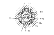
図6は電動パワーステアリング装置の他の構成を示す要部の拡大した断面図、図7は図6のVII −VII 線の断面図である。
この電動パワーステアリング装置は、実施の形態1のように転がり軸受6と離隔した位置に継体2を配置する代わりに、軸部32に結合された伝動筒部35を転がり軸受6の内輪6aに内嵌し、該伝動筒部35内に伝動孔50a,50aを有する非円形の弾性体50を保持し、該弾性体50の伝動孔50a,50aに出力軸11側の偏心ピン12,12を嵌入することにより出力軸11及びウォーム3を連動連結したものである。
6 is an enlarged cross-sectional view of a main part showing another configuration of the electric power steering apparatus, and FIG. 7 is a cross-sectional view taken along the line VII-VII in FIG.
In this electric power steering apparatus, instead of disposing the
伝動筒部35は筒部12aよりも大径に形成されており、内側に非円形の伝動孔35aが設けられており、該伝動孔35aに弾性体50が内嵌されている。また、伝動筒部35の外周部には転がり軸受6に対する軸線方向への移動を規制する段部35b及び止め輪35cが設けられている。
弾性体50は伝動孔35aに対応して非円形に形成されており、偏心した位置に2つの伝動孔50a,50aが設けられている。
The
The
実施の形態2にあっては、ウォーム3の偏角支点となる転がり軸受6の内側に伝動孔50a,50aを有する弾性体50が配置されており、該弾性体50に伝動筒部35が外嵌され、弾性体50の伝動孔50a,50aに偏心ピン12,12が嵌入されているため、弾圧部材30により噛合部に予圧が加えられる場合、転がり軸受6への支持部(転がり軸受6の軸線方向中央近傍位置O)を支点として偏角するウォーム3の連動連結部でのラジアル隙間量を低減でき、しかも、バックラッシュ量の調整代を充分に確保することができる。
その他の構成及び作用は実施の形態1と同様であるため、同様の部品については同じ符号を付し、その詳細な説明及び作用効果の説明を省略する。
In the second embodiment, the
Since other configurations and operations are the same as those of the first embodiment, the same components are denoted by the same reference numerals, and detailed description thereof and description of operations and effects are omitted.
尚、以上説明した実施の形態では、回転中心軸のアキシャル方向両側に可撓凸部23,23を有する継体2を備え、各可撓凸部23,23を撓ませるように構成したが、その他、回転中心軸のアキシャル方向一側にだけ可撓凸部23を有する継体を備え、1つの可撓凸部23を撓ませることによりウォーム3を軸線方向に押圧するように構成してもよい。この場合、出力軸11及び軸部32の一方を可撓凸部23に当接させ、出力軸11及び軸部32の他方には継体2の回転中心軸のアキシャル方向他側に当接する凸部を突設し、継体2のアキシャル方向への移動を規制する。このように回転中心軸部に凸部を設けることにより、出力軸11の軸線に対する継体2の撓みを阻害しないため、継体2からウォーム3に加わるラジアル方向の弾性復元力を低減できる。
In the embodiment described above, the joint 2 having the flexible
また、可撓性を有する継体2は撓み抑制手段22を有する構成としたが、その他、この継体2は撓み抑制手段22が設けられていない構成としてもよい。また、継体2は合成ゴム、合成樹脂等の弾性材料により形成された構成とする他、可撓性を有する金属板により形成され、回転中心軸のアキシャル方向一側又は両側に薄肉の可撓凸部23を有する構成としてもよい。また、撓み抑制手段22は合繊糸22aからなる構成である他、巻き掛けられた合繊糸22aのように長円形となる筒体からなる構成としてもよいし、また、各伝動孔21a,21bの周りに配置された筒体からなる構成としてもよいし、また、図8、図9に示すように板厚方向が出力軸11の軸線方向となり、回転中心軸から4つの板片が放射状に延出された略+字形の芯体からなる構成としてもよい。
Moreover, although the flexible
図8は撓み抑制手段の他の構成を示す拡大断面図、図9は図8のIX−IX線の断面図である。撓み抑制手段22は、板厚方向が出力軸11の軸線方向となり、中心部から4つの板片22cが放射状に延出された略+字形の芯体22bからなる。この芯体22bは各伝動孔21a,21bに対応する4つの成形用ピンがキャビティに突設された成形用型の前記キャビティに配置され、この状態で前記キャビティに合成ゴム、合成樹脂等の可撓性を有する材料を充填して成形することにより継体2の各伝動孔21a,21bの間を芯体22bにより補強し、出力軸11の回転方向へ撓み難いようにしている。芯体22bは継体2の弾性材料よりも高い剛性を有する鉄板、アルミニウム板、合成樹脂板等の材料からなる。尚、芯体22bなどからなる撓み抑制手段25を有する構成においても、電動モータ1が駆動されない操舵領域での操舵負荷を低減することができる。
FIG. 8 is an enlarged cross-sectional view showing another configuration of the deflection suppressing means, and FIG. 9 is a cross-sectional view taken along the line IX-IX in FIG. The bending suppression means 22 includes a substantially + -shaped
また、以上説明した実施の形態では、出力軸11及び軸部32とは別個に形成された偏心ピン12,34を出力軸11及び軸部32に装着した構成としたが、その他、偏心ピン12,34は出力軸11,軸部32とそれぞれ一体に形成された構成としてもよい。
In the embodiment described above, the
また、以上説明した実施の形態では、回転中心間距離Hを調節可能とした電動パワーステアリング装置について説明したが、その他、回転中心間距離Hを調節することができない電動パワーステアリング装置であってもよい。
また、以上説明した実施の形態では、弾圧手段として引張りコイルバネからなる弾圧部材30を用いたが、その他、圧縮コイルバネ等からなる弾圧部材を用いてもよいのであり、弾圧手段の構成、及び弾圧手段の配置位置は特に制限されない。
Further, in the embodiment described above, the electric power steering apparatus in which the distance H between the rotation centers can be adjusted has been described. However, other electric power steering apparatuses in which the distance H between the rotation centers cannot be adjusted are also described. Good.
In the embodiment described above, the
また、以上説明した実施の形態では、減速歯車機構Aとしてウォーム3である駆動歯車及びウォームホイール4である従動歯車を備えたウォーム歯車としたが、その他、ベベルギヤ、ハイポイドギヤ、ヘリカルギヤ等であってもよい。
In the embodiment described above, the reduction gear mechanism A is a worm gear having a drive gear that is a
1 電動モータ
11 出力軸
12,34 偏心ピン
2 継体
21a,21b 伝動孔(連動連結部)
22 撓み抑制手段
23 可撓凸部
3 ウォーム(駆動歯車)
4 ウォームホイール(従動歯車)
5 操舵手段
6 転がり軸受
7 支持部材
75 収容孔
8 軸受部材
83 弾性筒体
30 弾圧部材(弾圧手段)
50 弾性体
DESCRIPTION OF SYMBOLS 1
22 Deflection suppression means 23 Flexible
4 Worm wheel (driven gear)
DESCRIPTION OF
50 Elastic body
Claims (4)
A drive gear interlocked to the output shaft of the electric motor, a rolling bearing that rotatably supports the electric motor side of the drive gear on a support member, a driven gear that meshes with the drive gear and is connected to steering means, In an electric power steering apparatus comprising a pressing means for pressing the non-electric motor side of the drive gear in a direction in which the distance between the rotation centers of the drive gear and the driven gear is shortened, and assisting the steering by the rotation of the electric motor, An electric power steering device, wherein an elastic body is disposed inside the rolling bearing, and the output shaft and the drive gear are interlocked and connected to the elastic body.
Priority Applications (1)
| Application Number | Priority Date | Filing Date | Title |
|---|---|---|---|
| JP2004112427A JP2005297613A (en) | 2004-04-06 | 2004-04-06 | Electric power steering device |
Applications Claiming Priority (1)
| Application Number | Priority Date | Filing Date | Title |
|---|---|---|---|
| JP2004112427A JP2005297613A (en) | 2004-04-06 | 2004-04-06 | Electric power steering device |
Publications (1)
| Publication Number | Publication Date |
|---|---|
| JP2005297613A true JP2005297613A (en) | 2005-10-27 |
Family
ID=35329709
Family Applications (1)
| Application Number | Title | Priority Date | Filing Date |
|---|---|---|---|
| JP2004112427A Pending JP2005297613A (en) | 2004-04-06 | 2004-04-06 | Electric power steering device |
Country Status (1)
| Country | Link |
|---|---|
| JP (1) | JP2005297613A (en) |
Cited By (6)
| Publication number | Priority date | Publication date | Assignee | Title |
|---|---|---|---|---|
| JP2010149573A (en) * | 2008-12-24 | 2010-07-08 | Jtekt Corp | Electric power steering device |
| JP2010167905A (en) * | 2009-01-22 | 2010-08-05 | Showa Corp | Electric power steering apparatus |
| JP2010167904A (en) * | 2009-01-22 | 2010-08-05 | Showa Corp | Electric power steering device |
| WO2012073726A1 (en) * | 2010-12-03 | 2012-06-07 | 株式会社ジェイテクト | Reduction gear, electric power steering device with reduction gear, and method for manufacturing reduction gear |
| JP2013104444A (en) * | 2011-11-10 | 2013-05-30 | Oiles Corp | Shaft coupling mechanism for electric power steering device |
| KR20150142273A (en) * | 2014-06-11 | 2015-12-22 | 현대모비스 주식회사 | Bearing bush |
-
2004
- 2004-04-06 JP JP2004112427A patent/JP2005297613A/en active Pending
Cited By (10)
| Publication number | Priority date | Publication date | Assignee | Title |
|---|---|---|---|---|
| JP2010149573A (en) * | 2008-12-24 | 2010-07-08 | Jtekt Corp | Electric power steering device |
| JP2010167905A (en) * | 2009-01-22 | 2010-08-05 | Showa Corp | Electric power steering apparatus |
| JP2010167904A (en) * | 2009-01-22 | 2010-08-05 | Showa Corp | Electric power steering device |
| WO2012073726A1 (en) * | 2010-12-03 | 2012-06-07 | 株式会社ジェイテクト | Reduction gear, electric power steering device with reduction gear, and method for manufacturing reduction gear |
| JP2012116432A (en) * | 2010-12-03 | 2012-06-21 | Jtekt Corp | Reduction gear, electric power steering device having the same, and method for manufacturing the reduction gear |
| CN103260998A (en) * | 2010-12-03 | 2013-08-21 | 株式会社捷太格特 | Reduction gear, electric power steering device with reduction gear, and method for manufacturing reduction gear |
| CN103260998B (en) * | 2010-12-03 | 2015-11-25 | 株式会社捷太格特 | Reductor, the band electric power-assisted steering apparatus of reductor and the method for the manufacture of reductor |
| JP2013104444A (en) * | 2011-11-10 | 2013-05-30 | Oiles Corp | Shaft coupling mechanism for electric power steering device |
| KR20150142273A (en) * | 2014-06-11 | 2015-12-22 | 현대모비스 주식회사 | Bearing bush |
| KR102151110B1 (en) | 2014-06-11 | 2020-09-02 | 현대모비스 주식회사 | Bearing bush |
Similar Documents
| Publication | Publication Date | Title |
|---|---|---|
| JP3951913B2 (en) | Electric power steering device | |
| JP4107326B2 (en) | Electric power steering device | |
| JP5708981B2 (en) | Electric power steering device | |
| JP4356485B2 (en) | Electric power steering device | |
| JP5645070B2 (en) | Electric power steering device | |
| JP4872372B2 (en) | Electric power steering device | |
| CN102398627B (en) | Driven steering device | |
| KR101398046B1 (en) | Shaft coupling mechanism | |
| JP4868215B2 (en) | Electric power steering device | |
| JP4385286B2 (en) | Electric power steering device | |
| WO2013161845A1 (en) | Electric power steering device | |
| JP2016124488A (en) | Electric power steering device | |
| JP4232536B2 (en) | Electric power steering device | |
| JP2004034874A (en) | Motor-driven power steering | |
| KR20110096816A (en) | Reducer of electric power assisted steering and electric power assisted steering with same | |
| JP2005297613A (en) | Electric power steering device | |
| JP2005289314A (en) | Electric power steering device | |
| JP2007186021A (en) | Electric power steering device | |
| JP2006151043A (en) | Electric power steering device | |
| JP2007120592A (en) | POWER TRANSMISSION MECHANISM, ELECTRIC POWER STEERING DEVICE INCLUDING THE SAME, ELASTIC TOothed Ring, | |
| JP2004237843A (en) | Electric power steering device | |
| JP6414665B2 (en) | Power transmission joint, worm reducer, and electric power steering device | |
| JP2006056296A (en) | Motor-driven power steering device | |
| JP2005231487A (en) | Electric power steering device | |
| JP5397662B2 (en) | Vehicle steering system |