JP2005297468A - Recording device - Google Patents
Recording device Download PDFInfo
- Publication number
- JP2005297468A JP2005297468A JP2004119847A JP2004119847A JP2005297468A JP 2005297468 A JP2005297468 A JP 2005297468A JP 2004119847 A JP2004119847 A JP 2004119847A JP 2004119847 A JP2004119847 A JP 2004119847A JP 2005297468 A JP2005297468 A JP 2005297468A
- Authority
- JP
- Japan
- Prior art keywords
- recording
- power cable
- main body
- apparatus main
- recording apparatus
- Prior art date
- Legal status (The legal status is an assumption and is not a legal conclusion. Google has not performed a legal analysis and makes no representation as to the accuracy of the status listed.)
- Pending
Links
- 230000032258 transport Effects 0.000 abstract description 9
- 239000000725 suspension Substances 0.000 abstract description 6
- 230000002093 peripheral effect Effects 0.000 description 3
- 239000000853 adhesive Substances 0.000 description 2
- 239000002184 metal Substances 0.000 description 2
- 239000004033 plastic Substances 0.000 description 2
- 230000001070 adhesive effect Effects 0.000 description 1
- 239000000919 ceramic Substances 0.000 description 1
- 239000003086 colorant Substances 0.000 description 1
- 238000004891 communication Methods 0.000 description 1
- 238000010586 diagram Methods 0.000 description 1
- 238000005516 engineering process Methods 0.000 description 1
- 238000010438 heat treatment Methods 0.000 description 1
- 238000001746 injection moulding Methods 0.000 description 1
- 239000002245 particle Substances 0.000 description 1
- 238000011144 upstream manufacturing Methods 0.000 description 1
Images

Landscapes
- Accessory Devices And Overall Control Thereof (AREA)
Abstract
【課題】 使用位置高さを容易に調節することができ、同時に電源ケーブルを容易に配線することができる記録装置を提供すること。
【解決手段】 吊り下げられた状態で記録媒体を略鉛直方向に搬送して記録する記録装置100の電源ケーブル120が、装置本体110から略鉛直方向上方に延伸している。これにより、吊り下げの長さを変更するのみで使用位置高さを調節することができ、電源ケーブルの引き回し等を考慮しなくても電源ケーブルを天井に配設されている電源に接続配線することができる。
【選択図】 図1
PROBLEM TO BE SOLVED: To provide a recording apparatus capable of easily adjusting the height of a use position and simultaneously wiring a power cable.
A power cable 120 of a recording apparatus 100 that transports and records a recording medium in a substantially vertical direction while being suspended extends from the apparatus main body 110 in a substantially vertical direction. As a result, the height of the use position can be adjusted simply by changing the length of the suspension, and the power cable is connected and wired to the power supply installed on the ceiling without considering the routing of the power cable. be able to.
[Selection] Figure 1
Description
本発明は、吊り下げられた状態で記録媒体を略鉛直方向に搬送して記録する記録装置に関する。 The present invention relates to a recording apparatus that transports and records a recording medium in a substantially vertical direction in a suspended state.
一般的な記録装置であるプリンタは、机上等に載置して使用されるが、机上等の省スペース化を目的として提案されているプリンタは、専用の固定スタンドに固定したり、壁面に設けたフック等に固定して使用されるようになっている。 A printer, which is a general recording device, is used by placing it on a desk or the like. However, a printer that has been proposed to save space on a desk or the like is fixed to a dedicated fixing stand or provided on a wall surface. It is designed to be used fixed to a hook or the like.
ユーザは、上述した固定スタンドや壁面フック等に固定して使用するプリンタの高さ方向の位置を調節したいときは、高さの異なる別の固定スタンドを用意したり壁面フックを付け替える必要があり、余計な手間や費用が掛かっている。また、プリンタのインターフェイスについては近年の通信技術の向上によりワイヤレス化が可能となっているが、電源ケーブルについては依然として家庭用電源等に接続する必要がある。このため、ユーザは、プリンタの高さ方向の位置を調節したときは、同時に電源ケーブルの引き回し等の配線も考慮する必要がある。 When the user wants to adjust the position in the height direction of the printer to be used while being fixed to the above-mentioned fixed stand or wall hook, etc., it is necessary to prepare another fixed stand having a different height or replace the wall hook. It takes extra time and money. Also, the printer interface can be made wireless by recent improvements in communication technology, but the power cable still needs to be connected to a household power source or the like. For this reason, when the user adjusts the position in the height direction of the printer, it is necessary to consider wiring such as routing of the power cable at the same time.
本発明は、上記のような課題に鑑みなされたものであり、その目的は、使用位置高さを容易に調節することができ、同時に電源ケーブルを容易に配線することができる記録装置を提供することにある。 The present invention has been made in view of the above-described problems, and an object of the present invention is to provide a recording apparatus capable of easily adjusting the height of a use position and simultaneously wiring a power cable. There is.
上記目的達成のため、本発明の記録装置では、吊り下げられた状態で記録媒体を略鉛直方向に搬送して記録する記録装置であって、電源ケーブルが、装置本体から略鉛直方向上方に延伸していることを特徴としている。これにより、吊り下げの長さを変更するのみで使用位置高さを調節することができ、電源ケーブルの引き回し等を考慮しなくても電源ケーブルを天井に配設されている電源に接続配線することができる。 In order to achieve the above object, the recording apparatus of the present invention is a recording apparatus that transports and records a recording medium in a substantially vertical state in a suspended state, and a power cable extends substantially upward in the vertical direction from the apparatus main body. It is characterized by that. As a result, the height of the use position can be adjusted simply by changing the length of the suspension, and the power cable is connected and wired to the power source installed on the ceiling without considering the routing of the power cable. be able to.
また、前記電源ケーブルは、前記装置本体の上面の略中央部から延伸していることを特徴としている。また、前記電源ケーブルが接続される電源ユニットは、前記装置本体内の略中央部に配設されていることを特徴としている。これにより、吊り下げたときに記録装置が傾斜してしまうことを防止することができる。また、前記電源ケーブルの前記装置本体に対する抜け止めが、前記装置本体を構成するフレーム部材に直接係合されていることを特徴としている。これにより、電源ケーブルの抜け止めを強固に固定することができる。 Further, the power cable is characterized by extending from a substantially central portion of the upper surface of the apparatus main body. Further, the power supply unit to which the power cable is connected is arranged at a substantially central portion in the apparatus main body. Thereby, it is possible to prevent the recording apparatus from being inclined when suspended. Further, the retaining of the power cable with respect to the apparatus main body is directly engaged with a frame member constituting the apparatus main body. Thereby, the retaining of the power cable can be firmly fixed.
また、前記電源ケーブルの長さを調節可能な調節手段が配設されていることを特徴としている。これにより、使用位置高さを容易に調節することができる。また、前記記録媒体の供給部は、前記記録媒体の記録面側を保持しており、前記記録媒体は、前記供給部から排出部に向かう略U字経路を搬送されることを特徴としている。これにより、記録媒体を記録ヘッド部分でプラテン側に押圧することができるので、記録ヘッドと記録媒体との距離を均一にして高記録精度を維持することができる。 Further, an adjusting means capable of adjusting the length of the power cable is provided. Thereby, use position height can be adjusted easily. The recording medium supply unit holds a recording surface side of the recording medium, and the recording medium is conveyed along a substantially U-shaped path from the supply unit to the discharge unit. As a result, the recording medium can be pressed toward the platen at the recording head portion, so that the distance between the recording head and the recording medium can be made uniform and high recording accuracy can be maintained.
また、装置固定用の吸着手段が、前記装置本体の背面側に配設されていることを特徴としている。これにより、プリンタを壁面等に容易に固定して安定化させることができる。また、媒体搬送経路が略鉛直方向を向いた状態で設置したときに姿勢を安定化させる第1の支持部材が、前記装置本体の下面側に装着されているとともに、媒体搬送経路が略水平方向を向いた状態で設置したときに姿勢を安定化させる第2の支持部材が、前記装置本体の背面側に装着されていることを特徴としている。これにより、使用場所に合わせた形態で記録することができる。 Further, the apparatus fixing suction means is disposed on the back side of the apparatus main body. Thereby, the printer can be easily fixed to the wall surface or the like and stabilized. In addition, the first support member that stabilizes the posture when the medium transport path is installed in a substantially vertical direction is mounted on the lower surface side of the apparatus main body, and the medium transport path is in the substantially horizontal direction. A second support member that stabilizes the posture when installed in a state of facing is mounted on the back side of the apparatus main body. Thereby, it can record in the form according to the place of use.
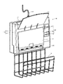
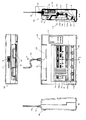
図1は、本発明の実施の形態に係る記録装置の1つであるインクジェット式プリンタの構成例を斜め前方から見た斜視図、図2は、その分解斜視図である。このインクジェット式プリンタ100は、扁平な直方体状の筐体(装置本体)110を備えており、吊り下げられた状態で用紙を略鉛直方向に搬送して記録が可能なように構成されている。したがって、使用場所の自由度が向上し、デザイン性も向上させることができる。なお、本実施形態では、用紙は上部から給紙して下部から排紙する構成としたが、用紙を下部から給紙して上部から排紙するように構成しても良い。
FIG. 1 is a perspective view of an example of the configuration of an ink jet printer that is one of recording apparatuses according to an embodiment of the present invention, and FIG. 2 is an exploded perspective view thereof. The
筐体110の上面には、本発明の特徴的な部分である電源ケーブル120が取り付けられている。この電源ケーブル120は、筐体110の上面から略鉛直方向上方に延伸するように取り付けられている。インクジェット式プリンタ100は、例えば天井から吊り下げられて使用されるが、そのときの吊り下げ手段としてチェーン等を用いても良く、また、この電源ケーブル120をチェーン等の代わりに用いることができる。これにより、部品点数を減少させることができ、また、デザイン性も向上させることができる。
A
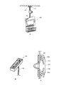
そして、図2に示すように、電源ケーブル120を吊り下げ手段として使用する場合、吊り下げられたインクジェット式プリンタ100が傾斜しないように、電源ケーブル120は筐体110の上面の略中央部から略鉛直方向上方に延伸するように取り付けられている。さらに、電源ケーブル120が接続される比較的重量のある電源ユニット121は、筐体110内の略中央部に配設されている。これにより、電源ケーブル120に対してインクジェット式プリンタ100の左右前後の重量はバランスするので、インクジェット式プリンタ100を真直ぐな状態で吊り下げることができる。したがって、給排紙や記録を安定的に行うことができ、高精度記録を維持することができる。
As shown in FIG. 2, when the
さらに、比較的重量のあるインクジェット式プリンタ100を引張上げておく必要があるので、電源ケーブル120の筐体110に対する抜け止め122は、筐体110を構成するフレーム(フレーム部材)101に直接係合されている。この抜け止め122は、周囲に溝122aが形成されており、この溝122a内にフレーム101の切り欠き縁部101aが嵌り込んで係合するようになっている。このような構成とすることにより、インクジェット式プリンタ100の落下による故障や破損等を防止することができる。この電源ケーブル120を吊り下げ手段として使用する場合、天井に配設されている電源に接続すれば良く、図を参照して説明する。
Furthermore, since it is necessary to pull up the relatively
図3は、上記電源ケーブル120を吊り下げ手段として使用したときを示す図である。図3(A)に示すように、インクジェット式プリンタ100は、電源ケーブル120が天井に配設されている一般的な電灯用の吊り下げ用ACプラグ123に結合接続されて吊り下げられている。この電源ケーブル120の先端には、図3(B)に示すような、吊り下げ用ACプラグ123に引っ掛けて結合接続可能な一般的な電灯用の引掛けACプラグ124が取り付けられている。このような引掛けACプラグ124は、吊り下げ用ACプラグ123に差し込んで捻るのみで結合接続でき、また、逆に捻るのみで結合接続を解除できるので、インクジェット式プリンタ100の吊り下げ及び取り外しを簡易に行うことができる。
FIG. 3 is a diagram showing the
また、この電源ケーブル120の途中には、図3(C)に示すような、一般的なブラインドの開閉用ひものストッパに用いられる調節手段がケーブル長さ調節手段125として取り付けられている。このようなケーブル長さ調節手段125は、電源ケーブル120を横に引っ張ってストッパローラ125aをカム面125bに沿って移動させるのみでストッパを解除して長さ調節でき、また、ストッパローラ125aをカム面125bに沿って元の位置に移動させるのみでストッパを掛けることができので、インクジェット式プリンタ100の吊り下げ高さを簡易に行うことができる。
Further, in the middle of the
なお、一般的な電灯用の電源ケーブルの長さを調節する手段であれば同様に使用可能である。例えば、楔形状であって先端が十字状に切り込まれ、電源ケーブルが貫装されている部材と、この部材の先端が差し込まれて切り込みが窄まることにより電源ケーブルを銜え込むとともに、余った電源ケーブルを巻き込んで収納する部材を備えたケーブル長さ調節手段でも使用することができる。 It should be noted that any means for adjusting the length of a general power cable for electric light can be used in the same manner. For example, a wedge-shaped member whose tip is cut in a cross shape and the power cable is inserted, and the tip of the member is inserted and the notch is narrowed, and the power cable is swallowed and the surplus It can also be used in a cable length adjusting means provided with a member that encloses and stores a power cable.
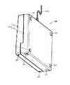
図4は、上記インクジェット式プリンタ100の背面側を示す図である。図4(A)に示すように、筐体110の背面側には、一般的な吸盤126が取り付けられる吸盤取付部126aが形成されている。そして、この吸盤取付部126aには吸盤126がインクジェット式プリンタ100の後方を向くようにして取り付けられる。図4(B)に示すように、このような吸盤126が着脱自在となるように筐体110の背面側に吸盤取付部126aを形成しておくことにより、インクジェット式プリンタ100を壁際に吊るしたり壁面に掛けるときに姿勢を安定させることができるので、給排紙や記録を安定的に行うことができ、高精度記録を維持することができる。
FIG. 4 is a view showing the back side of the
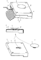
図5は、上記インクジェット式プリンタ100の底面から背面に掛けて示す斜視図である。筐体110の底面の四隅には、インクジェット式プリンタ100を用紙の搬送経路が略鉛直となるようにして机上等に載置したときに、インクジェット式プリンタ100を支持するゴム足(第1の支持部材)127が装着されている。また、筐体110の背面の四隅には、インクジェット式プリンタ100を用紙の搬送経路が略水平となるようにして机上等に載置したときに、インクジェット式プリンタ100を支持するゴム足(第2の支持部材)128が装着されている。このようなゴム足127、128を装着することにより、机上等とは小さな面積で接触することになるので、インクジェット式プリンタ100が机上等でがたつくことは無くなる。したがって、インクジェット式プリンタ100の姿勢を安定化させ給排紙や記録を安定的に行うことができ、高精度記録を維持することができる。
FIG. 5 is a perspective view showing the
筐体110は、図1に示すように、前面が開放された器状に形成された背面ケース111と、この背面ケース111と略同一寸法の背面が開放された器状に形成された前面ケース112を備えている。背面ケース111と前面ケース112は、開放面が結合されて内部にプリンタの主要構成部品が収納されるようになっている。背面ケース111及び前面ケース112は、金属またはプラスチックにより形成されている。金属で形成する場合は、プレス加工等により周壁と一体で成形し、もしくは別体で成形して溶接もしくは接着剤により接着等する。プラスチックで形成する場合は、射出成形等により周壁と一体で成形し、もしくは別体で成形して接着剤により接着等する。
As shown in FIG. 1, the
そして、背面ケース111と前面ケース112は、図示しないネジもしくはスナップフィット等による締結等により両側に別途装着される一対のフレーム101を介して結合されている。このスナップフィットによるフレーム101との締結を採用することにより、背面ケース111と前面ケース112の取り外し・組み付け作業が簡易になるので、紙詰まり等のエラー解除や部品交換等の修理を迅速に完了させることができる。
The back case 111 and the
前面ケース112は、上部の略中央部に矩形状の給紙口113が穿設されている。そして、この給紙口113には、斜め前上方に突出する形状の給紙トレイ114が着脱自在に取り付けられている。また、前面ケース112は、下部の略中央部に矩形状の排紙口115が穿設されている。そして、この排紙口115には、下方に突出する形状の排紙バスケット116が着脱自在に取り付けられている。そして、前面ケース112は、給紙口113の下部から排紙口115の上部にかけて開放されており、この開放部を覆う開閉自在な蓋117が配設されている。この蓋117は、上端部を軸としてケース面から手前上方に旋回自在となるように軸支持されている。
The
また、前面ケース112は、蓋117の隣接位置に操作パネル130が配設されている。この操作パネル130には、電源ボタン131、リセットボタン132、排紙ボタン133等が配設されており、筐体110に内蔵されている制御部の専用コントローラボード等に電気配線接続されている。この操作パネル130の各ボタン131〜133等を操作することにより、インクジェット式プリンタ100の起動・印刷・停止等を行うことができるようになっている。
Further, the
図6は、上記インクジェット式プリンタ100の外観及び内部構造を示す図である。このインクジェット式プリンタ100は、筐体110の内部に用紙の搬送部140及び記録部150が配設されている。搬送部140は、給紙トレイ114から給紙口113を通り、プラテン153を通って排紙口115へ至る紙経路に沿って用紙を搬送する機能を有しており、上流側から下流側にかけて以下の部材が順に配設されている。すなわち、給紙ローラ141、上下に対向配置されている紙送りローラ142a及び従動ローラ142b、上下に対向配置されている排紙ローラ143a及び排紙スターホイール143bが、筐体110内の上部から下部にかけて配設されている。
FIG. 6 is a view showing an appearance and an internal structure of the
給紙ローラ141は、断面の一部が切り欠かれたD字状に形成されており、間欠的に回転して用紙を摩擦搬送するようになっている。紙送りローラ142aの軸及び排紙ローラ143aの軸は、各両端がフレーム101に、負荷軽減のために軸受を介して軸支持されている。この紙送りローラ142aの外周面には、搬送時の摩擦係数を高めるためにゴムやセラミック粒子等が被覆され、排紙ローラ143aの外周面には、搬送時の摩擦係数を高めるために複数のゴムローラが嵌入されている。また、従動ローラ142bは、紙送りローラ142aの下方に軸に沿って複数配列され、フレーム101に固定されている従動ローラ受け台144に係止されており、図示しない1枚の板バネにより紙送りローラ142aに当接されて付勢されている。
The
排紙スターホイール143bは、排紙ローラ143aの軸に沿って複数配列され、排紙スターホイール143bの軸は、各両端がフレーム101に、負荷軽減のために軸受を介して軸支持されている。そして、図示しない捩りコイルバネ等により排紙ローラ143aに当接されて付勢されている。紙送りローラ142aと従動ローラ142bは、給紙口115から挿入される用紙を挟持して送り出すようになっている。排紙ローラ143aと排紙スターホイール143bは、紙送りローラ142aと従動ローラ142bから搬送されてくる用紙を挟持して送り出すようになっている。
A plurality of paper
このような構成において、用紙は、給紙トレイ114から給紙ローラ141で給紙され、紙送りローラ142aからプラテン153を通って排紙ローラ143aへと搬送されることになる。ここで、図6(D)の一点鎖線で示すように、上記各部材114等により形成される用紙の搬送経路Lは、略U字状となるように形成されている。したがって、搬送途中の用紙は、紙送りローラ142a付近を最下端として前後に湾曲した形状となるので、紙送りローラ142aと排紙ローラ143aの間に位置する用紙の部分はプラテン153に押し付けられることになる。このため、プラテン153上の用紙の部分と後述する記録ヘッド152との距離を常に一定に保持することができるので、記録精度を向上させることができる。
In such a configuration, the paper is fed from the
記録部150は、プラテン153上に搬送されてきた用紙の部分に対して記録する機能を有しており、紙送りローラ142aと排紙ローラ143aの間に以下の部材が配設されている。すなわち、用紙の搬送直交方向(主走査方向)に移動可能なキャリッジ151、このキャリッジ151の下端面に取り付けられた記録ヘッド152、キャリッジ151の下方で移動方向に沿って配設されたプラテン153、キャリッジ151の移動を案内するキャリッジガイド軸154が配設されている。
The
キャリッジ151は、後部に形成されている軸受け部がキャリッジガイド軸154に摺動自在に貫装され、前部に装着されているフレーム102に摺動自在に載置されている。キャリッジ151は、インクジェット式プリンタ100が非記録状態であるオフ状態もしくはスタンバイ状態のときは待機位置(ホームポジション)に位置しており、記録状態のときはホームポジションを離脱して搬送されてくる用紙の両側端部間をキャリッジガイド軸154とフレーム102に沿って往復移動するようになっている。
The
記録ヘッド152は、ブラックインクを吐出するブラックインク用記録ヘッドと、イエロー、シアン、マゼンタ等の各色のインクを吐出する複数のカラーインク用記録ヘッドを備えている。そして、記録ヘッド152は、キャリッジ151に搭載された各色毎のインクカートリッジ151aに繋がる複数の圧力発生室とそれらに繋がるノズルを備えており、例えば圧電素子や発熱素子等により圧力発生室内の圧力を変動させて、圧力発生室内に貯留されているインクをノズルから吐出させるようになっている。
The
プラテン153は、紙送りローラ142aと排紙ローラ143aの間であってキャリッジ151の下方で移動方向に沿って延びる矩形容器状に形成されている。このプラテン153は、背面ケース111に対して図示しないネジやスナップフィット等により着脱自在に装着されている。キャリッジガイド軸154は、両端がフレーム101に軸支持されている。
The
上述したインクジェット式プリンタ100によれば、吊り下げられた状態にあるとき、電源ケーブル120は筐体110から略鉛直方向上方に延伸しているので、吊り下げの長さを変更するのみで使用位置高さを調節することができ、電源ケーブル120の引き回し等を考慮しなくても電源ケーブル120を天井に配設されている電源に接続配線することができる。
According to the
また、電源ケーブル120は、筐体110の上面の略中央部から延伸し、また、電源ユニット121は、筐体110内の略中央部に配設されているので、吊り下げたときにインクジェット式プリンタ100が傾斜してしまうことを防止することができる。また、電源ケーブル120の抜け止め122が、フレーム101に直接係合されているので、電源ケーブル120の抜け止め122を強固に固定することができる。
The
また、電源ケーブル120の長さを調節可能なケーブル長さ調節手段125が配設されているので、使用位置高さを容易に調節することができる。また、給紙トレイ114は、用紙の記録面側を保持しており、用紙は、給紙トレイ114から排紙バスケット116に向かう略U字経路を搬送されるので、用紙を記録ヘッド152部分でプラテン153側に押圧することができ、記録ヘッド152と用紙との距離を均一にして高記録精度を維持することができる。また、吸盤126が、筐体110の背面側に配設されているので、インクジェット式プリンタ100を壁面等に容易に固定して安定化させることができる。また、ゴム足127、128が装着されているので、使用場所に合わせた形態で記録することができる。
Further, since the cable length adjusting means 125 capable of adjusting the length of the
吊り下げられた状態で記録可能な記録装置であれば、例えばファクシミリ装置やコピー装置等の記録装置にも適用可能である。 Any recording apparatus capable of recording in a suspended state can be applied to a recording apparatus such as a facsimile apparatus or a copying apparatus.
100 インクジェット式プリンタ、101、102 フレーム、110 筐体、111 背面ケース、112 前面ケース、113 給紙口、114 給紙トレイ、115 排紙口、116 排紙バスケット、117 蓋、120 電源ケーブル、121 電源ユニット、122 抜け止め、124 引掛けACプラグ、125 ケーブル長さ調節手段、126 吸盤、127、128 ゴム足、140 搬送部、141 給紙ローラ、142a 紙送りローラ、142b 従動ローラ、143a 排紙ローラ、143b 排紙スターホイール、150 記録部、151 キャリッジ、152 記録ヘッド、153 プラテン、154 キャリッジガイド軸
100 Inkjet printer, 101, 102 frame, 110 housing, 111 back case, 112 front case, 113 paper feed port, 114 paper feed tray, 115 paper discharge port, 116 paper discharge basket, 117 lid, 120 power cable, 121 Power supply unit, 122 retaining stopper, 124 hook AC plug, 125 cable length adjusting means, 126 suction cup, 127, 128 rubber foot, 140 transport section, 141 paper feed roller, 142a paper feed roller, 142b driven roller, 143a paper discharge Roller, 143b Paper discharge star wheel, 150 recording unit, 151 carriage, 152 recording head, 153 platen, 154 carriage guide shaft
Claims (8)
電源ケーブルが、装置本体から略鉛直方向上方に延伸していることを特徴とする記録装置。 A recording apparatus that conveys and records a recording medium in a substantially vertical direction in a suspended state,
A recording apparatus, wherein the power cable extends substantially vertically upward from the apparatus main body.
A first support member that stabilizes the posture when installed in a state where the medium conveyance path is oriented substantially vertically is mounted on the lower surface side of the apparatus main body, and the medium conveyance path faces substantially horizontal. The recording apparatus according to claim 1, wherein a second support member that stabilizes a posture when installed in a mounted state is attached to a back side of the apparatus main body. .
Priority Applications (1)
| Application Number | Priority Date | Filing Date | Title |
|---|---|---|---|
| JP2004119847A JP2005297468A (en) | 2004-04-15 | 2004-04-15 | Recording device |
Applications Claiming Priority (1)
| Application Number | Priority Date | Filing Date | Title |
|---|---|---|---|
| JP2004119847A JP2005297468A (en) | 2004-04-15 | 2004-04-15 | Recording device |
Publications (1)
| Publication Number | Publication Date |
|---|---|
| JP2005297468A true JP2005297468A (en) | 2005-10-27 |
Family
ID=35329592
Family Applications (1)
| Application Number | Title | Priority Date | Filing Date |
|---|---|---|---|
| JP2004119847A Pending JP2005297468A (en) | 2004-04-15 | 2004-04-15 | Recording device |
Country Status (1)
| Country | Link |
|---|---|
| JP (1) | JP2005297468A (en) |
Cited By (1)
| Publication number | Priority date | Publication date | Assignee | Title |
|---|---|---|---|---|
| US7864345B2 (en) * | 1999-05-25 | 2011-01-04 | Silverbrook Research Pty Ltd | Printer with vertical media flow path |
-
2004
- 2004-04-15 JP JP2004119847A patent/JP2005297468A/en active Pending
Cited By (1)
| Publication number | Priority date | Publication date | Assignee | Title |
|---|---|---|---|---|
| US7864345B2 (en) * | 1999-05-25 | 2011-01-04 | Silverbrook Research Pty Ltd | Printer with vertical media flow path |
Similar Documents
| Publication | Publication Date | Title |
|---|---|---|
| TWI546203B (en) | Complex apparatus | |
| JP5906622B2 (en) | Inkjet recording device | |
| CN100361821C (en) | image recording device | |
| JP6035725B2 (en) | Image recording device | |
| JP6161869B2 (en) | Liquid ejector | |
| US9090074B2 (en) | Ink-jet recording apparatus | |
| JP2007223067A (en) | Carriage moving device and image reading device having the same | |
| JP2005297468A (en) | Recording device | |
| JP5381334B2 (en) | Image forming apparatus | |
| JP4941334B2 (en) | Inkjet recording device | |
| JP6988962B2 (en) | Recording device | |
| JP4254794B2 (en) | Multi-function device | |
| JP5098673B2 (en) | Inkjet recording device | |
| JP7035678B2 (en) | Liquid sprayer | |
| JP6439721B2 (en) | Liquid ejector | |
| US20030058323A1 (en) | Printer | |
| JP7375851B2 (en) | Sheet conveyance device and image forming device | |
| JP2001096726A (en) | Ink jet recording device | |
| US10315446B2 (en) | Recording apparatus | |
| CN118494039A (en) | Recording device | |
| JP2019010839A (en) | Supply device | |
| JP5772056B2 (en) | Medium transport mechanism and recording apparatus provided with the same | |
| JP6439720B2 (en) | Liquid ejector | |
| JP4507122B2 (en) | Image forming apparatus | |
| JP2012144859A (en) | Lid body opening/closing mechanism and electronic equipment equipped with the same |