JP2005297418A - Thermal transfer printer - Google Patents
Thermal transfer printer Download PDFInfo
- Publication number
- JP2005297418A JP2005297418A JP2004118717A JP2004118717A JP2005297418A JP 2005297418 A JP2005297418 A JP 2005297418A JP 2004118717 A JP2004118717 A JP 2004118717A JP 2004118717 A JP2004118717 A JP 2004118717A JP 2005297418 A JP2005297418 A JP 2005297418A
- Authority
- JP
- Japan
- Prior art keywords
- ink ribbon
- thermal transfer
- transfer printer
- printing
- ink
- Prior art date
- Legal status (The legal status is an assumption and is not a legal conclusion. Google has not performed a legal analysis and makes no representation as to the accuracy of the status listed.)
- Pending
Links
- 238000010438 heat treatment Methods 0.000 claims abstract description 17
- 230000009477 glass transition Effects 0.000 claims description 4
- 238000002844 melting Methods 0.000 claims description 3
- 230000008018 melting Effects 0.000 claims description 3
- 239000003086 colorant Substances 0.000 abstract 1
- 238000000034 method Methods 0.000 description 4
- 238000003672 processing method Methods 0.000 description 4
- 238000010586 diagram Methods 0.000 description 3
- 230000007246 mechanism Effects 0.000 description 3
- 239000000853 adhesive Substances 0.000 description 2
- 230000001070 adhesive effect Effects 0.000 description 2
- 230000015572 biosynthetic process Effects 0.000 description 2
- 239000000463 material Substances 0.000 description 2
- 230000008569 process Effects 0.000 description 2
- 238000000859 sublimation Methods 0.000 description 2
- 230000008022 sublimation Effects 0.000 description 2
- 230000037303 wrinkles Effects 0.000 description 2
- 230000008901 benefit Effects 0.000 description 1
- 230000008859 change Effects 0.000 description 1
- 230000000694 effects Effects 0.000 description 1
- 230000007613 environmental effect Effects 0.000 description 1
- 239000000446 fuel Substances 0.000 description 1
- 239000000049 pigment Substances 0.000 description 1
- 238000003825 pressing Methods 0.000 description 1
- GGCZERPQGJTIQP-UHFFFAOYSA-N sodium;9,10-dioxoanthracene-2-sulfonic acid Chemical compound [Na+].C1=CC=C2C(=O)C3=CC(S(=O)(=O)O)=CC=C3C(=O)C2=C1 GGCZERPQGJTIQP-UHFFFAOYSA-N 0.000 description 1
- 230000000087 stabilizing effect Effects 0.000 description 1
- 238000011144 upstream manufacturing Methods 0.000 description 1
- 239000002699 waste material Substances 0.000 description 1
Images
Landscapes
- Electronic Switches (AREA)
- Impression-Transfer Materials And Handling Thereof (AREA)
Abstract
Description
本発明は、ロール状インクリボンを使用する熱転写プリンタに関し、特に使用済みインクリボンを判読不能とする機能を有する熱転写プリンタに関する。 The present invention relates to a thermal transfer printer using a roll-shaped ink ribbon, and more particularly to a thermal transfer printer having a function of making a used ink ribbon unreadable.
従来より、熱転写プリンタとして、感熱式プリンタ、昇華型熱転写プリンタが知られている。この熱転写プリンタは、インクを塗布したインクリボンに印字ヘッドで熱を加え色素を、受像シートに転写させて印字するプリンタである。この熱転写プリンタは、加える熱を制御することで印字濃度を細かく変化させることができ、例えばインクジェットプリンタや電子写真方式では不可能な銀塩写真のような連続階調の表現が可能で高画質が得られるという特徴を有している。 Conventionally, thermal printers and sublimation thermal transfer printers are known as thermal transfer printers. This thermal transfer printer is a printer that prints by transferring heat to an image receiving sheet by applying heat to an ink ribbon to which ink has been applied with a print head. This thermal transfer printer can finely change the print density by controlling the applied heat. For example, it can express continuous tones like a silver salt photograph, which is impossible with an ink jet printer or an electrophotographic system, and has high image quality. It has the characteristic of being obtained.
しかしながら、使用済み(印字後/印画後)インクリボンをそのまま廃棄処理をすると、インクリボンに残された反転印字されている個人情報や公表したくない内容等が簡単に判読され、機密事項が他に洩れる危険性がある。 However, if the used (after printing / printing) ink ribbon is disposed of as it is, personal information remaining on the ink ribbon that has been printed in reverse or content that you do not want to publish can be easily read, and other confidential matters There is a risk of leakage.
そこで、使用済みインクリボンを使用後速やかに判読不能にする対策が提案されている。 In view of this, measures have been proposed to make a used ink ribbon unreadable immediately after use.
例えば、1)インクリボンカセットの巻取りリボン軸側に使用済みインクリボンを裁断する裁断機を設ける方法(例えば、特許文献1参照)や、2)巻取リールに巻取られて積層する印字済インクリボン同士を固着させるべく印字済インクリボンに粘着剤を付与する粘着剤付与手段を設ける方法(例えば、特許文献3参照)や、カッタで使用済みインクリボンをカットできるように、スリットが入ったインクリボンカセット(例えば、特許文献2参照)等が提案されている。
しかしながら、上記の、1)はコストアップにつながる。2)は固着したインクリボンは焼却処理時に容易に燃えず余分な燃料を必要とするか、不燃物扱いになり環境適正に問題がある。3)はセキュリティには不完全な面がある。 However, the above 1) leads to an increase in cost. In 2), the fixed ink ribbon does not burn easily during the incineration process and requires extra fuel, or it is treated as a non-combustible material and there is a problem in environmental suitability. 3) is incomplete in security.
本発明は、使用済みインクリボンを、判読不能にし、容易に焼却処理が可能な状態になる機能を有する熱転写プリンタを提供することを目的とする。 An object of the present invention is to provide a thermal transfer printer having a function of making a used ink ribbon unreadable and capable of being easily incinerated.
上記目的は、下記の構成によって達成することができる。 The above object can be achieved by the following configuration.
(1)インクを塗布したロール状インクリボンに印字ヘッドで熱を加え色素を受像シートに転写させて印字し、印字し終った使用済みインクリボンを処理する手段を有する熱転写プリンタにおいて、前記手段は、前記印字ヘッドの下流測に設けられ、前記使用済みインクリボンのインク面同志を対面させるように重ね合わせ、折畳む機能を有することを特徴とする熱転写プリンタ(第1の発明)。 (1) In a thermal transfer printer having a means for applying heat to a roll-shaped ink ribbon to which ink has been applied by a print head to transfer a dye onto an image receiving sheet for printing, and processing the used ink ribbon after printing, A thermal transfer printer (first invention) provided on the downstream side of the print head and having a function of overlapping and folding so that the ink surfaces of the used ink ribbons face each other.
(2)インクを塗布したロール状インクリボンに印字ヘッドで熱を加え色素を受像シートに転写させて印字し、印字し終った使用済みインクリボンを処理する手段を有する熱転写プリンタにおいて、前記手段は、前記印字ヘッドの下流側に設けられ、使用済みインクリボンを紐状に撚る紐打ち機能を有することを特徴とする熱転写プリンタ。(第2の発明)。 (2) In a thermal transfer printer having means for applying heat to a roll-shaped ink ribbon to which ink has been applied by a print head to transfer a dye to an image receiving sheet for printing, and processing the used ink ribbon after printing, A thermal transfer printer provided on the downstream side of the print head and having a stringing function of twisting a used ink ribbon into a string shape. (Second invention).
本発明により、使用済みインクリボンに反転された個人情報、機密事項等が判読不可能になり、インクリボンそのものを容易に焼却できるようになる。 According to the present invention, personal information, confidential matters, etc. reversed on a used ink ribbon become unreadable, and the ink ribbon itself can be easily incinerated.
以下、本発明の実施の形態である画像形成装置の一例を図面に基づいて説明する。 Hereinafter, an example of an image forming apparatus according to an embodiment of the present invention will be described with reference to the drawings.
なお、本発明の実施の形態における説明では、本明細書に用いる用語により発明の技術範囲が限定されることはない。 In the description of the embodiment of the present invention, the technical scope of the invention is not limited by the terms used in this specification.
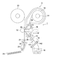
図1は本発明に係る熱転写プリンタの主要部を示す略図である。 FIG. 1 is a schematic view showing a main part of a thermal transfer printer according to the present invention.
図1において、1は熱転写プリンタ(以下、単に装置本体ともいう。)で、その主要部である。10は、ロール状のインクリボンで、後述するリボンカートリッジ3に装填されている。11は、印字ヘッドで不図示の機構によってW方向に往復移動する。12は、プラテンロールで、当該プラテンロール面に受像シートである印字用紙20と前記インクリボン10を介して、前記印字ヘッド11を押圧して、前記印字ヘッド11から画像情報に対応した熱を加え、インクリボン10の色素を前記印字用紙20上に転写して画像を形成する。21は、所定の長さだけ印字用紙を送る用紙引出しローラ、22はカッタ、23は搬送ローラ、24は、プリント収納皿である。13は、使用済みのインクリボン10を搬送するピンチローラ、14は、本発明に係る折畳み手段であり、詳細は後述する。16は、インクリボン10の廃棄箱である。
In FIG. 1, reference numeral 1 denotes a thermal transfer printer (hereinafter also simply referred to as an apparatus main body), which is the main part. A roll-
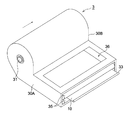
図4は、リボンカートリッジの外観を示す図である。 FIG. 4 is a view showing the appearance of the ribbon cartridge.
図1、図4において、インクリボン10は巻取り軸31にロール状に巻かれており、当該巻取り軸31はカートリッジ筐体の両側面30A、30Bで支持されている。また、巻取り軸31には多少の摩擦が加味されており、インクリボン10を引き出し時には、図1にで示す点線Tのようにある程度のテンションが加えられた状態となる。
1 and 4, the
また、リボンの走行を安定させるためのローラ対34と35との間には、開口部36が設けられ、当該開口部36を通して印字ヘッド11がインクリボン10を、プラテンローラ12上の印字用紙20に押圧する。
An
インクリボン10のロールの先端部はローラ対35に挟持され、更に先端部の縁は巻戻り防止用の先端部材33が挟着されている。当該先端部材33はインクリボンと別部材でもよいし、インクリボンを熱加工して棒状に厚く固着してもよい。
The leading end portion of the roll of the
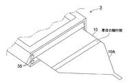
またインクリボン10を各ローラや開口部(穴)等に通すことを容易にするためにリボンの先端部に可燃性の材質のリード部10Aを貼着し、セッティングの容易化を図ってもよい(図5参照)。
In addition, in order to make it easy to pass the
図5は、リード部付きのインクリボンの一例を示す図である。 FIG. 5 is a diagram illustrating an example of an ink ribbon with a lead portion.
次に、上記熱転写プリンタ1の画像形成プロセスについて図1を基にして説明する。 Next, the image forming process of the thermal transfer printer 1 will be described with reference to FIG.
はじめに、リボンカートリッジ3を装置本体に装填する。装填に際しては、前記先端部材33を圧着解除状態にあるピンチローラ13の間隙に通し、インクリボン10を山形ガイド141に覆い、折重ねた状態にして圧着解除状態にある加熱ローラ142(内部にハロゲンヒータ144を設けてある。)と圧着ローラ143(図3参照)との間隙に通して、ピンチローラ13、圧着ローラ143を圧着状態にする。また、不図示のカートリッジに収納されている印字用紙20の先端部を引出しローラ21に挟持しておく。以上の準備作業でプリント作成が可能となる。
First, the
画像形成スタートと共に、前記印字ヘッド11は、不図示の押圧機構によって左方に移動し、点線Tに位置にあったインクリボン10を、テンションに抗して、実線のように、印字用紙20と共にプラテンローラ12に押し当てる。次に、不図示の駆動部からの動力が各ローラに伝達され、インクリボン10と印字用紙20は、インク面が印字用紙20に密着した状態で同速度で送られる。
With the start of image formation, the
一方、印字ヘッド11には、画像データに対応するドット状の発熱抵抗体が発熱し、印字用紙20上のインクを昇華して印字用紙20上に画像を形成する。画像形成が終了すると、印字ヘッド11は右方に移動し、プラテンローラ12への押圧を解除する。画像が形成された印字用紙20は所定の長さだけ引出しローラ21、搬送ローラ23によって搬送され、一時停止後カッタ22にて切断され、プリント収納皿24に送られる。使用済みのインクリボン10はピンチローラ13および加熱ローラ142と圧着ローラ143とに圧着、加熱されインク面の同志が対面に二つに重なった状態で廃棄箱16へと進む(あるいは、巻き取ってもよい。)。
On the other hand, the dot-like heating resistor corresponding to the image data generates heat on the
ここで、本発明の特徴について説明する。 Here, the features of the present invention will be described.
図2は、折畳み手段を有した使用済みインクリボン処理方法を示す図である。 FIG. 2 is a diagram showing a used ink ribbon processing method having folding means.
図2(a)において、141は不図示の装置本体枠体に取り付けられた山形(凸)ガイドである。凸型にすることによって皺がなく、折畳みやすくする効果が得られる。仮に、凹型にすると、皺が発生しやすくなり搬送上問題となりやすい。
In FIG. 2A,
図では、山形ガイド141は1個であるが、折畳まれた使用済みインクリボンの下流に更に山形ガイドを設け、同じように幾重にも折畳むようにしてもよい。
In the figure, there is one
使用済みのインクリボン10は折畳まれた状態で加熱ローラ142、加圧ローラ142間のニップ部でTg(ガラス転移温度)以上に熱せられ、インク面同志が密着し、インクは昇華することになる。
In a state where the used
すなわち、インクリボンに残された反転印字されている画像は、インクリボン10を折畳んだ状態にして、加熱、加圧することによって、インク面同志が密着し合い、仮に両面を剥がしても反転印字を判読することは不可能となるので、機密事項が他に洩れる危険性を回避できる。
That is, the reversely printed image that remains on the ink ribbon is printed in the reverse direction even if the ink surfaces are brought into close contact with each other by heating and pressurizing the
図2(b)は複数の山を設けた山形ガイドである。この場合、複数回折り重ねた状態で加熱、加圧されるので更に機密性が保たれる利点がある。 FIG. 2B shows a mountain-shaped guide provided with a plurality of peaks. In this case, since heating and pressurization are performed in a state where a plurality of diffraction patterns are repeated, there is an advantage that confidentiality is further maintained.
以上、第1の発明は、使用済みインクリボンを複数に折り、重ねて合わす折畳み手段と、加熱手段によって反転印字を判読不可能にすることを特徴としている。 As described above, the first invention is characterized in that the reverse printing is made unreadable by the folding means that folds the used ink ribbon into a plurality and overlaps them and the heating means.
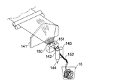
図3は、紐打ち手段を有した使用済みインクリボン処理方法を示す図である。 FIG. 3 is a diagram showing a used ink ribbon processing method having stringing means.
図3において、150は紐打ち手段であるダイスで、リボン搬送の上流側が大きく、下流側が小さくなるテーパ付き開口部151を有している。当該ダイス150は、不図示の装置本体枠体に保持されている。
In FIG. 3,
第1の発明と同様に、使用済みインクリボン10を山形ガイド141に覆い、捻った状態で前記開口部151をを通して、加熱ローラ142、加圧ローラ142間に挟持し、ローラの回転によりインクリボン10を引き抜くことで、インクリボン10は圧縮された、紐152になって、加熱ローラ142、加圧ローラ142間でTg(ガラス転移温度)以上に熱せられ、廃棄箱16に落ちる。また、この場合のリボンは、廃棄箱16の中で紐状の状態でも適度に空気を含んでおり、巻取って固着したものより燃焼処理がし易くなっているので燃えるゴミとして排出が可能である。
As in the first invention, the used
すなわち、インクリボンに残された反転印字されている画像は、インクリボン10を紐152のような状態にして、加熱、加圧することによって、反転印字形状が乱れ、判読することは不可能となるので、機密事項が他に洩れる危険性を回避できる。なお、前記ダイス150ではなく、捻り回転機構を山形ガイド141と加熱ローラ142、加圧ローラ142との間に設け使用済みリボンを紐状にしてもよい。
That is, the reversely printed image remaining on the ink ribbon becomes unreadable because the reversely printed shape is disturbed by heating and pressurizing the
第2の発明は、使用済みインクリボンを紐打ち手段で紐状に撚り、さらに、加熱手段によって反転印字を乱し、判読不可能にすることを特徴としている。 The second invention is characterized in that a used ink ribbon is twisted in a string shape by a string striking means, and further, reverse printing is disturbed by a heating means to make it unreadable.
以上の発明により、個人情報や公表したくない内容等が簡単に判読され、機密事項が他に洩れる危険性を防止することができる。 According to the above invention, personal information, contents that the user does not want to make public, etc. can be easily read, and the risk of leaking confidential matters to others can be prevented.
なお、上記実施の形態では、昇華型の熱転写プリンタを基に説明したが、熱溶融型の場合にも本発明は適用してもよい。 Although the above embodiment has been described based on a sublimation type thermal transfer printer, the present invention may also be applied to a case of a thermal melting type.
1 熱転写プリンタ
11 印字ヘッド
12 プラテンローラ
14 折畳み手段
141 山形ガイド
142 加熱ローラ
143 加圧ローラ
150 ダイス
20 印字用紙
22 カッタ
3 リボンカートリッジ
32 ローラ対
DESCRIPTION OF SYMBOLS 1
Claims (5)
Priority Applications (1)
| Application Number | Priority Date | Filing Date | Title |
|---|---|---|---|
| JP2004118717A JP2005297418A (en) | 2004-04-14 | 2004-04-14 | Thermal transfer printer |
Applications Claiming Priority (1)
| Application Number | Priority Date | Filing Date | Title |
|---|---|---|---|
| JP2004118717A JP2005297418A (en) | 2004-04-14 | 2004-04-14 | Thermal transfer printer |
Publications (1)
| Publication Number | Publication Date |
|---|---|
| JP2005297418A true JP2005297418A (en) | 2005-10-27 |
Family
ID=35329549
Family Applications (1)
| Application Number | Title | Priority Date | Filing Date |
|---|---|---|---|
| JP2004118717A Pending JP2005297418A (en) | 2004-04-14 | 2004-04-14 | Thermal transfer printer |
Country Status (1)
| Country | Link |
|---|---|
| JP (1) | JP2005297418A (en) |
Cited By (10)
| Publication number | Priority date | Publication date | Assignee | Title |
|---|---|---|---|---|
| JP2007196634A (en) * | 2006-01-30 | 2007-08-09 | Toppan Forms Co Ltd | Ink ribbon cutting device |
| JP2008080796A (en) * | 2006-08-31 | 2008-04-10 | Dainippon Printing Co Ltd | Thermal transfer printer |
| JP2008105363A (en) * | 2006-09-28 | 2008-05-08 | Dainippon Printing Co Ltd | Thermal transfer type image forming apparatus |
| JP2008126510A (en) * | 2006-11-20 | 2008-06-05 | Dainippon Printing Co Ltd | Thermal transfer type image forming apparatus |
| JP2008126511A (en) * | 2006-11-20 | 2008-06-05 | Dainippon Printing Co Ltd | Thermal transfer type image forming apparatus |
| JP2011031517A (en) * | 2009-08-03 | 2011-02-17 | Dainippon Printing Co Ltd | Ink ribbon cassette and cutting unit |
| US8081201B2 (en) | 2006-08-31 | 2011-12-20 | Dai Nippon Printing Co., Ltd. | Thermal transfer printer |
| JP2012056128A (en) * | 2010-09-07 | 2012-03-22 | Citizen Holdings Co Ltd | Thermal transfer printer |
| CN107776219A (en) * | 2017-09-28 | 2018-03-09 | 湖州天骊正隆电子科技有限公司 | A kind of printing device with color band winding chopping up apparatus |
| CN108406889A (en) * | 2018-03-16 | 2018-08-17 | 湖州富丽华色带有限公司 | A kind of ink ribbon tape base production cutter device |
-
2004
- 2004-04-14 JP JP2004118717A patent/JP2005297418A/en active Pending
Cited By (11)
| Publication number | Priority date | Publication date | Assignee | Title |
|---|---|---|---|---|
| JP2007196634A (en) * | 2006-01-30 | 2007-08-09 | Toppan Forms Co Ltd | Ink ribbon cutting device |
| JP2008080796A (en) * | 2006-08-31 | 2008-04-10 | Dainippon Printing Co Ltd | Thermal transfer printer |
| US8081201B2 (en) | 2006-08-31 | 2011-12-20 | Dai Nippon Printing Co., Ltd. | Thermal transfer printer |
| US8400485B2 (en) | 2006-08-31 | 2013-03-19 | Dai Nippon Printing Co., Ltd. | Thermal transfer printer |
| JP2008105363A (en) * | 2006-09-28 | 2008-05-08 | Dainippon Printing Co Ltd | Thermal transfer type image forming apparatus |
| JP2008126510A (en) * | 2006-11-20 | 2008-06-05 | Dainippon Printing Co Ltd | Thermal transfer type image forming apparatus |
| JP2008126511A (en) * | 2006-11-20 | 2008-06-05 | Dainippon Printing Co Ltd | Thermal transfer type image forming apparatus |
| JP2011031517A (en) * | 2009-08-03 | 2011-02-17 | Dainippon Printing Co Ltd | Ink ribbon cassette and cutting unit |
| JP2012056128A (en) * | 2010-09-07 | 2012-03-22 | Citizen Holdings Co Ltd | Thermal transfer printer |
| CN107776219A (en) * | 2017-09-28 | 2018-03-09 | 湖州天骊正隆电子科技有限公司 | A kind of printing device with color band winding chopping up apparatus |
| CN108406889A (en) * | 2018-03-16 | 2018-08-17 | 湖州富丽华色带有限公司 | A kind of ink ribbon tape base production cutter device |
Similar Documents
| Publication | Publication Date | Title |
|---|---|---|
| JP4732774B2 (en) | Printer and printing method | |
| JP2005297418A (en) | Thermal transfer printer | |
| JPH03211077A (en) | Thermal transfer printer | |
| JP4403891B2 (en) | Printer | |
| JP2008194893A (en) | Printing apparatus and printing method | |
| JPH08192562A (en) | Thermal transfer recorder | |
| JP5578402B2 (en) | Thermal transfer printer | |
| JP2005305800A (en) | Thermal transfer printer | |
| JP2006007662A (en) | Thermal transfer printer | |
| JP4698556B2 (en) | Thermal transfer type image forming apparatus | |
| JP4698557B2 (en) | Thermal transfer type image forming apparatus | |
| JPS6364781A (en) | Thermal transfer recording apparatus | |
| JP2007260912A (en) | Thermal transfer recording device | |
| JP7260437B2 (en) | ink ribbon | |
| JP4957203B2 (en) | Thermal transfer type image forming apparatus | |
| JPS6096477A (en) | Heat transfer type recorder | |
| JP4375984B2 (en) | Stencil printing machine | |
| JPH0288253A (en) | Thermal transfer printer | |
| JP2005350218A (en) | Printer | |
| JP2003094751A (en) | Thermal transfer printer | |
| JP4959834B2 (en) | Printer and printing method | |
| JP2003341118A (en) | Thermal transfer printer | |
| JPH08281985A (en) | Thermal transfer recording apparatus and method | |
| JP2006315237A (en) | Thermal printer | |
| JPH07214856A (en) | Image forming equipment |


