JP2005297329A - Automatic traveling stapler - Google Patents
Automatic traveling stapler Download PDFInfo
- Publication number
- JP2005297329A JP2005297329A JP2004115932A JP2004115932A JP2005297329A JP 2005297329 A JP2005297329 A JP 2005297329A JP 2004115932 A JP2004115932 A JP 2004115932A JP 2004115932 A JP2004115932 A JP 2004115932A JP 2005297329 A JP2005297329 A JP 2005297329A
- Authority
- JP
- Japan
- Prior art keywords
- stapler
- base
- image processing
- processing machine
- stapler body
- Prior art date
- Legal status (The legal status is an assumption and is not a legal conclusion. Google has not performed a legal analysis and makes no representation as to the accuracy of the status listed.)
- Granted
Links
- 230000007246 mechanism Effects 0.000 claims abstract description 32
- 230000006835 compression Effects 0.000 description 5
- 238000007906 compression Methods 0.000 description 5
- 238000010586 diagram Methods 0.000 description 2
- 238000010521 absorption reaction Methods 0.000 description 1
- 238000005452 bending Methods 0.000 description 1
Images


Classifications
-
- B—PERFORMING OPERATIONS; TRANSPORTING
- B27—WORKING OR PRESERVING WOOD OR SIMILAR MATERIAL; NAILING OR STAPLING MACHINES IN GENERAL
- B27F—DOVETAILED WORK; TENONS; SLOTTING MACHINES FOR WOOD OR SIMILAR MATERIAL; NAILING OR STAPLING MACHINES
- B27F7/00—Nailing or stapling; Nailed or stapled work
- B27F7/17—Stapling machines
Landscapes
- Engineering & Computer Science (AREA)
- Mechanical Engineering (AREA)
- Life Sciences & Earth Sciences (AREA)
- Forests & Forestry (AREA)
- Folding Of Thin Sheet-Like Materials, Special Discharging Devices, And Others (AREA)
- Portable Nailing Machines And Staplers (AREA)
- Dovetailed Work, And Nailing Machines And Stapling Machines For Wood (AREA)
Abstract
Description
本発明はベースに対してステープラ本体をスライド自在に設けた自走式ステープラに関するものである。 The present invention relates to a self-propelled stapler in which a stapler body is slidably provided with respect to a base.
一般に、複写機、ファクシミリ、これらの複合機などの画像処理機に、ステープラを搭載しているものが知られている。 In general, an image processing machine such as a copying machine, a facsimile machine, or a multifunction machine of these is equipped with a stapler.
ところで、用紙をステープルで綴る場合、用紙をステープラの綴り部まで送り、その後ステープラが綴り作動し、綴り終了後は再び用紙を綴り部から退避させるという動作が必要になる。 By the way, in the case of binding paper with staples, it is necessary to send the paper to the stapler's binding portion, then the stapler performs the binding operation, and after the binding is finished, the operation of retracting the paper again from the binding portion is required.
そこで、従来は複写機、ファクスなどの画像処理機内に用紙搬送装置を設置し、搬送装置に用紙の把持・解放機構と進入・退避機構を設けることにより、用紙を把持し、ステープラの綴り部まで搬送して解放し、綴り作動終了後に退避作動させていた。
しかしながら、画像処理機内に上述のような用紙搬送装置を搭載しようとすると、用紙の把持・解放や進入・退避に関する諸機構を設けなければならない。このため、処理機自体が複雑になってコストが高くなるとともに、大型化してしまい、小型、低コストの画像処理機にステープラを搭載することの障害になっていた。 However, in order to mount the above-described paper transport device in the image processing machine, various mechanisms relating to gripping / release of paper and entry / retraction must be provided. For this reason, the processing machine itself becomes complicated and the cost increases, and the processing machine itself increases in size, which is an obstacle to mounting a stapler on a small and low-cost image processing machine.
本発明が解決しようとする課題は、上記問題点を解決し、用紙搬送装置がある画像処理機においては、小型化とコストダウンが可能となり、用紙を搬送するための特別の装置がない画像処理機においては、ステープラの搭載が可能となる自走式ステープラを提供する点にある。 The problem to be solved by the present invention is to solve the above problems, and in an image processing machine having a paper transport device, it is possible to reduce the size and cost, and image processing without a special device for transporting paper The machine is to provide a self-propelled stapler that can be loaded with a stapler.
前記目的を達成するため、本発明に係る自走式ステープラは、内部で画像処理された用紙に綴りを施すための画像処理機に搭載されるステープラであって、ベース上にステープラ本体を相対的にスライド自在に設け、ベースとステープラ本体との間にスライド機構を設けるとともに、上記画像処理機に上記ベースを固定し、上記スライド機構によって、綴り作動時にはステープラ本体を所定の綴り位置にスライドさせ、綴り作動終了後に原位置にスライドさせる自走式ステープラであって、上記スライド機構を、上記ステープラ本体の両側に回動可能に設けられたリンクの一端を上記ベースに係合可能に設ける構成としたことを特徴とする。 In order to achieve the above object, a self-propelled stapler according to the present invention is a stapler mounted on an image processing machine for binding paper that has undergone image processing therein, and the stapler body is relatively mounted on a base. The slide mechanism is provided between the base and the stapler body, the base is fixed to the image processor, and the slide mechanism slides the stapler body to a predetermined spelling position during the spelling operation. A self-propelled stapler that is slid to an original position after the end of a spelling operation, wherein the slide mechanism is configured such that one end of a link rotatably provided on both sides of the stapler main body is engageable with the base. It is characterized by that.
請求項1に係る発明によれば、用紙搬送装置がある画像処理機においては、小型化とコストダウンが可能となり、用紙を搬送するための特別の装置がない画像処理機においては、ステープラの搭載が可能となる。そして、スライド機構を、ステープラ本体の両側に回動可能に設けられたリンクの一端をベースに係合可能に設ける構成としたので、リンクの動作を利用してステープラを多様に利用することができる。 According to the first aspect of the present invention, it is possible to reduce the size and cost of an image processing machine with a paper transport device, and mount a stapler in an image processing machine without a special device for transporting paper. Is possible. In addition, since the slide mechanism is configured so that one end of a link rotatably provided on both sides of the stapler main body can be engaged with the base, the stapler can be used in various ways by utilizing the operation of the link. .
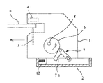
図1は本発明に係る自走式ステープラの概要図で、1はステープラ本体、2はベースを示す。 FIG. 1 is a schematic view of a self-propelled stapler according to the present invention, where 1 is a stapler body and 2 is a base.
ベース2は、ステープラ本体1の底面と略同じ大きさの盤状に形成されたものである。
The
ステープラ本体1はベース2上に相対的にスライド自在に設けられている。なお、ステープラは、被綴り用紙aにステープルを貫通させるステープル打ち出し手段3と貫通したステープル脚を折り曲げるクリンチ手段4とを備えた綴り装置で、電動モータを駆動源とするものであるが、ここでは、ステープラ本体1にステープル打ち出し手段とクリンチ手段が設けられている場合だけでなく、打ち出し手段またはクリンチ手段のみが設けられ、他方のクリンチ手段または打ち出し手段は画像処理機に設けられるものも含むものとする。
The
ベース2とステープラ本体1との間にはスライド機構5が設けられている。つまり、ステープラ本体1の両側には偏心カム6とL形リンク7が配置されている。偏心カム6は円板の偏心位置に回転軸8を設けたもので、ステープラ本体1の内部の駆動機構(図示せず)に作動連結している。L形リンク7の屈曲部はステープラ本体1の両側に設けた支持軸9に回動自在に支持され、一方の部分7aは上記偏心カム6に係合可能に配置されている。他方の部分7bには長穴10が形成されている。
A
ベース2には、上記各L形リンク7の他方の端部の長穴10に係合する軸11が設けられている。また、ベース2とステープラ本体1との間には圧縮バネ12が設けられている。
The
上記構成によれば、偏心カム6を回転させることにより、図2のように偏心カム6に係合したL形リンク7の一方7aの端部が図の反時計方向に押し込まれるので、他方の端部は上記圧縮バネ12のバネ力に抗して軸を図の右方向に押し出すように作用する。したがって、ベース2が画像処理機等に固定されている時は、ステープラ本体1がベース2に対して図の左方向にスライド移動する。そして、被綴り用紙aの綴り位置まで移動すると、綴り装置を作動させて打ち出し手段が駆動されて綴り作動が行われる。移動端を越えると、L形リンク7が軸11を押す力はなくなるので、上記圧縮バネ12のバネ力が勝り、ステープラ本体1はベース2本体に対して初期位置にスライド移動する。
According to the above configuration, when the
なお、偏心カム6と圧縮バネ12とによりストロークを一定にする吸収機構を設けるのが好ましい。
It is preferable to provide an absorption mechanism that makes the stroke constant by the
上記構成のステープラを複写機、ファクシミリなどの画像処理機の内部に搭載する場合、ベース2を画像処理機Aの所定位置に固定し、ステープラ本体1がベース2に対して移動するときは、画像処理機内で画像処理された用紙aの綴り部位(図2の位置)と上記綴り部位から最も遠い位置(初期位置、図1の位置)との間でスライドするように設定すればよい。また、偏心カム6は画像処理が終了して綴りの準備ができたときに、リンク7がステープラ本体1を綴り部位まで移動させる所定角度だけ回転し、綴り作動が終了した後にさらに初期位置まで回転するように設定すればよい。
When the stapler having the above configuration is mounted inside an image processing machine such as a copying machine or a facsimile, when the
以上の構成によれば、綴りの準備ができてステープラ本体1の駆動機構によりスライド機構5が作動し、偏心カム6が所定角度だけ回転すると、図2に示すように、ステープラ本体1が偏心カム6からの押圧力により綴り位置までスライド移動する。その移動端で偏心カム6が停止し、ステープラ本体1で綴り装置が作動して綴り作動が終了する。その後、偏心カム6がさらに図1に示す初期位置まで回転すると、ステープラ本体1は圧縮バネ12のバネ力により綴り位置から退避して初期位置までスライド移動する。これによって、綴りの1サイクルが終了する。
According to the above configuration, when the preparation for the spelling is completed and the
上述のように、ベース2を画像処理機に固定することにより、綴り作動の前後には、スライド機構5によってステープラ本体1を画像処理機の所定位置(綴り位置)に進入、退避させることによって用紙aの綴りを行なうことができる。したがって、用紙搬送装置がある画像処理機においては、小型化とコストダウンが可能となり、用紙を搬送するための特別の装置がない画像処理機においては、ステープラの搭載が可能となる。
As described above, by fixing the
また、ベース2は、ステープラ本体1の底面と略同じ大きさの盤状に形成されているから、ステープラ全体をコンパクトにすることができる。
In addition, since the
ところで、上記スライド機構は、前記ステープラ本体1の両側に回動可能に設けられたリンクの一端を前記ベース2に係合可能に設けたものであるから、図3に示すような構成のステープラを得ることができる。
By the way, the slide mechanism is provided with one end of a link rotatably provided on both sides of the stapler
すなわち、同図においてステープラはベース2とステープラ本体1とから構成されることは上述のものと同じであるが、このステープラは、中心軸14を中心に回動自在になっている。また、ステープラの初期位置のさらに後方には、被綴り用紙aの綴り側の端面に対応するようにプレート15が配置されている。プレート15には被綴り用紙aの綴り側の端面と平行で、上記端面の長さよりも長い直線部16の端部から前方に突出する突部17が形成されている。
That is, the stapler is composed of the
なお、ステープラを上記プレート15の端縁に沿って移動させる駆動手段が設けられているものとする。
It is assumed that driving means for moving the stapler along the edge of the
上記構成によれば、図4に示されるように、上記直線部16の一端側でステープラのスライド機構5が作動してステープラ本体1がスライドして用紙aに綴りが行われた後、再びステープラ本体1が初期位置に戻り、さらに駆動機構によりステープラ本体1を上記直線部の他端側に移動し、再びスライド機構5が作動することにより用紙aの別の位置に綴りが行われる。このようにして、用紙aに対し2〜3個所のステープルを直線上に打ち込むことができる。
According to the above configuration, as shown in FIG. 4, after the
また、ステープラ本体1をプレート15の突部17まで移動させてスライド機構5を作動させると、ステープラ本体1の両側のL形リンク7のうち一方のL形リンク7が回動するときに上記突部17に当たるので、さらにL形リンク7が回動すると、突部17を押圧するが、突部17は動かないので、ベース2とともにステープラ本体1が中心軸14を中心に一定の角度だけ回転する。一定の角度回転すると同時に、ステープラ本体1はベース2に対してスライドして綴りが行なわれる。このため、用紙aに対してコーナー綴じができる。なお、綴り作動終了後には上記L形リンク7の上記突部17に対する押圧力はなくなるので、上記ベース2を原位置まで回転させるためのバネ(図示せず)を取りつけておけばよい。
Further, when the
次に、図5は、ベース2とステープラ本体1とを別個に設け、ステープラ本体1には上述のように偏心カム6とL形リンク7とを取りつけ、ベース2には直線部2aと突部2bとが形成されている。なお、18は逃げ部である。
Next, FIG. 5 shows that the
上記構成によれば、上記直線部2aの一端側でステープラのスライド機構5が作動して左右のL形リンク7が回動すると、図6(a)(b)に示されるように、L形リンク7の一端がベース2の直線部2aを押すので、ステープラ本体1がスライドし、用紙aに綴りが行われる。その後、再びステープラ本体1が初期位置に戻り、さらに駆動機構によりステープラ本体1を上記直線部2aの他端側に移動し、再びスライド機構5が作動することにより用紙aの別の位置に綴りが行われる。このようにして、用紙aに対し直線に沿って複数のステープルを打ち込むことができる。
According to the above configuration, when the
また、ステープラ本体1をプレートの突部2bまで移動させてスライド機構5を作動させると、ステープラ本体1の両側のL形リンク7のうち一方のL形リンク7が回動するときに上記突部2bに当たるので、さらにL形リンク7が回動すると、突部2bを押圧するが、突部2bは動かないので、ステープラ本体1が回転する。ステープラ本体1が一定の角度回転した後、スライドして綴りが行なわれる。このため、用紙aに対してコーナー綴じができる。なお、この場合も、綴り作動終了後には上記L形リンク7の上記突部2bに対する押圧力はなくなるので、上記ベース2を原位置まで回転させるためのバネ(図示せず)を取りつけておけばよい。
Further, when the
上述のように、スライド機構5を、ステープラ本体1の両側に回動可能に設けられたL形リンク7の一端をベース2に係合可能に設ける構成としたので、L形リンク7の動作を利用してステープラを多様に利用することができる。
As described above, the
1 ステープラ本体
2 ベース
5 スライド機構
7 L形リンク
1
Claims (1)
上記スライド機構を、上記ステープラ本体の両側に回動可能に設けられたリンクの一端を上記ベースに係合可能に設ける構成としたことを特徴とする自走式ステープラ。
A stapler mounted on an image processing machine for binding paper that has undergone image processing inside, wherein a stapler body is slidably provided on a base, and a slide mechanism is provided between the base and the stapler body. A self-propelled stapler that fixes the base to the image processing machine, slides the stapler main body to a predetermined spelling position at the time of the spelling operation, and slides the original position after the spelling operation by the slide mechanism,
A self-propelled stapler characterized in that the slide mechanism has a structure in which one end of a link rotatably provided on both sides of the stapler body is provided to be engageable with the base.
Priority Applications (7)
| Application Number | Priority Date | Filing Date | Title |
|---|---|---|---|
| JP2004115932A JP4572566B2 (en) | 2004-04-09 | 2004-04-09 | Self-propelled stapler |
| US11/547,670 US8123097B2 (en) | 2004-04-09 | 2005-04-07 | Self -propelled stapler |
| CNB2005800122258A CN100475469C (en) | 2004-04-09 | 2005-04-07 | Self-propelled stapler |
| EP05728591A EP1733856B1 (en) | 2004-04-09 | 2005-04-07 | Self-propelled stapler |
| PCT/JP2005/006877 WO2005097440A1 (en) | 2004-04-09 | 2005-04-07 | Self-propelled stapler |
| DE602005018754T DE602005018754D1 (en) | 2004-04-09 | 2005-04-07 | CLAMPING MACHINE WITH OWN DRIVE |
| TW094110967A TW200600290A (en) | 2004-04-09 | 2005-04-07 | Self-propelled stapler |
Applications Claiming Priority (1)
| Application Number | Priority Date | Filing Date | Title |
|---|---|---|---|
| JP2004115932A JP4572566B2 (en) | 2004-04-09 | 2004-04-09 | Self-propelled stapler |
Publications (2)
| Publication Number | Publication Date |
|---|---|
| JP2005297329A true JP2005297329A (en) | 2005-10-27 |
| JP4572566B2 JP4572566B2 (en) | 2010-11-04 |
Family
ID=35124911
Family Applications (1)
| Application Number | Title | Priority Date | Filing Date |
|---|---|---|---|
| JP2004115932A Expired - Fee Related JP4572566B2 (en) | 2004-04-09 | 2004-04-09 | Self-propelled stapler |
Country Status (7)
| Country | Link |
|---|---|
| US (1) | US8123097B2 (en) |
| EP (1) | EP1733856B1 (en) |
| JP (1) | JP4572566B2 (en) |
| CN (1) | CN100475469C (en) |
| DE (1) | DE602005018754D1 (en) |
| TW (1) | TW200600290A (en) |
| WO (1) | WO2005097440A1 (en) |
Families Citing this family (4)
| Publication number | Priority date | Publication date | Assignee | Title |
|---|---|---|---|---|
| EP1904442B1 (en) * | 2005-07-01 | 2011-09-07 | Eli Lilly And Company | Histamine h3 receptor agents, preparation and therapeutic uses |
| JP5333083B2 (en) | 2009-09-08 | 2013-11-06 | マックス株式会社 | Electric stapler |
| CN110625712B (en) * | 2019-09-18 | 2021-04-20 | 浙江发恩集成房屋有限公司 | Prefabricated plate processing equipment for ceiling heating and refrigerating system and processing method thereof |
| KR20210092474A (en) * | 2020-01-16 | 2021-07-26 | 휴렛-팩커드 디벨롭먼트 컴퍼니, 엘.피. | paper separation mechanism of stapleless binder |
Citations (5)
| Publication number | Priority date | Publication date | Assignee | Title |
|---|---|---|---|---|
| JPH0416392A (en) * | 1990-05-09 | 1992-01-21 | Ricoh Co Ltd | Image formation post-processing device |
| JPH0472271A (en) * | 1990-07-10 | 1992-03-06 | Ikegami Tsushinki Co Ltd | Processing object holding device |
| JPH08101551A (en) * | 1994-09-30 | 1996-04-16 | Canon Inc | Sheet post-processing apparatus and image forming apparatus including the same |
| JPH09295749A (en) * | 1996-04-30 | 1997-11-18 | Minolta Co Ltd | Finisher |
| JP2001206629A (en) * | 2000-01-26 | 2001-07-31 | Ricoh Elemex Corp | Recording paper post-treatment device of image forming apparatus |
Family Cites Families (7)
| Publication number | Priority date | Publication date | Assignee | Title |
|---|---|---|---|---|
| US5092509A (en) * | 1988-08-19 | 1992-03-03 | Canon Kabushiki Kaisha | Sheet stapling apparatus |
| JP2642681B2 (en) * | 1988-08-19 | 1997-08-20 | キヤノン株式会社 | Sheet sorting and binding device |
| US5290020A (en) * | 1991-07-16 | 1994-03-01 | Mita Industrial Co., Ltd. | Sheet finishing device with calculating means for efficient operation |
| JP2998611B2 (en) * | 1995-09-28 | 2000-01-11 | 富士ゼロックス株式会社 | Stapler unit |
| DE19843869C2 (en) | 1998-09-25 | 2001-06-13 | Bdt Buero Datentech Gmbh | Device for stapling by stapling stacked sheets of a record carrier |
| KR100499900B1 (en) * | 1998-10-31 | 2005-09-26 | 주식회사신도리코 | Finisher Stapler Drive |
| US7063248B2 (en) * | 2001-10-31 | 2006-06-20 | Krdc Co., Ltd. | Stapler moving guide device |
-
2004
- 2004-04-09 JP JP2004115932A patent/JP4572566B2/en not_active Expired - Fee Related
-
2005
- 2005-04-07 TW TW094110967A patent/TW200600290A/en not_active IP Right Cessation
- 2005-04-07 WO PCT/JP2005/006877 patent/WO2005097440A1/en not_active Ceased
- 2005-04-07 US US11/547,670 patent/US8123097B2/en not_active Expired - Fee Related
- 2005-04-07 DE DE602005018754T patent/DE602005018754D1/en not_active Expired - Lifetime
- 2005-04-07 CN CNB2005800122258A patent/CN100475469C/en not_active Expired - Fee Related
- 2005-04-07 EP EP05728591A patent/EP1733856B1/en not_active Expired - Lifetime
Patent Citations (5)
| Publication number | Priority date | Publication date | Assignee | Title |
|---|---|---|---|---|
| JPH0416392A (en) * | 1990-05-09 | 1992-01-21 | Ricoh Co Ltd | Image formation post-processing device |
| JPH0472271A (en) * | 1990-07-10 | 1992-03-06 | Ikegami Tsushinki Co Ltd | Processing object holding device |
| JPH08101551A (en) * | 1994-09-30 | 1996-04-16 | Canon Inc | Sheet post-processing apparatus and image forming apparatus including the same |
| JPH09295749A (en) * | 1996-04-30 | 1997-11-18 | Minolta Co Ltd | Finisher |
| JP2001206629A (en) * | 2000-01-26 | 2001-07-31 | Ricoh Elemex Corp | Recording paper post-treatment device of image forming apparatus |
Also Published As
| Publication number | Publication date |
|---|---|
| TWI324549B (en) | 2010-05-11 |
| TW200600290A (en) | 2006-01-01 |
| DE602005018754D1 (en) | 2010-02-25 |
| WO2005097440A1 (en) | 2005-10-20 |
| CN1946525A (en) | 2007-04-11 |
| EP1733856B1 (en) | 2010-01-06 |
| US20080272167A1 (en) | 2008-11-06 |
| EP1733856A1 (en) | 2006-12-20 |
| CN100475469C (en) | 2009-04-08 |
| EP1733856A4 (en) | 2008-09-24 |
| JP4572566B2 (en) | 2010-11-04 |
| US8123097B2 (en) | 2012-02-28 |
Similar Documents
| Publication | Publication Date | Title |
|---|---|---|
| US7311238B2 (en) | Electric stapler | |
| US6981627B2 (en) | Electric stapler having an apparatus to bend staple legs and the apparatus | |
| US8393617B2 (en) | Sheet alignment device | |
| JP4572566B2 (en) | Self-propelled stapler | |
| US9738007B2 (en) | Electric stapler | |
| JPH02219601A (en) | Stapler | |
| JP4103724B2 (en) | Lock mechanism of paper presser table in stapler | |
| JP5262299B2 (en) | Clinch positioning mechanism in stapler | |
| US8136810B1 (en) | Sheet alignment and ejection mechanism | |
| JP2002200572A (en) | Stapler | |
| JP2004001450A (en) | Staple forming apparatus | |
| JP2011131444A (en) | Stapler for saddle stitching | |
| TW564213B (en) | Built-in equipment type | |
| JP2006240879A (en) | Sheet processing apparatus and image forming apparatus | |
| US10695942B2 (en) | Stapler | |
| JP4909170B2 (en) | Sheet post-processing device | |
| CN100522498C (en) | Stapler | |
| JP2002355772A (en) | Stapler | |
| CN100503176C (en) | Stapler | |
| JPH0427592A (en) | Automatic stapler of copying machine | |
| JP4830476B2 (en) | Stapler | |
| JP2005035151A (en) | Staple supply mechanism of electromotive stapler | |
| JP2007296616A (en) | Paper support mechanism in paper pressing processor | |
| JP2009248226A (en) | Electric stapler | |
| JP2001105346A (en) | Staple feed mechanism for electric stapler |
Legal Events
| Date | Code | Title | Description |
|---|---|---|---|
| A621 | Written request for application examination |
Free format text: JAPANESE INTERMEDIATE CODE: A621 Effective date: 20060908 |
|
| A131 | Notification of reasons for refusal |
Free format text: JAPANESE INTERMEDIATE CODE: A131 Effective date: 20091208 |
|
| A521 | Request for written amendment filed |
Free format text: JAPANESE INTERMEDIATE CODE: A523 Effective date: 20100128 |
|
| A131 | Notification of reasons for refusal |
Free format text: JAPANESE INTERMEDIATE CODE: A131 Effective date: 20100316 |
|
| A521 | Request for written amendment filed |
Free format text: JAPANESE INTERMEDIATE CODE: A523 Effective date: 20100517 |
|
| TRDD | Decision of grant or rejection written | ||
| A01 | Written decision to grant a patent or to grant a registration (utility model) |
Free format text: JAPANESE INTERMEDIATE CODE: A01 Effective date: 20100720 |
|
| A01 | Written decision to grant a patent or to grant a registration (utility model) |
Free format text: JAPANESE INTERMEDIATE CODE: A01 |
|
| A61 | First payment of annual fees (during grant procedure) |
Free format text: JAPANESE INTERMEDIATE CODE: A61 Effective date: 20100802 |
|
| R150 | Certificate of patent or registration of utility model |
Ref document number: 4572566 Country of ref document: JP Free format text: JAPANESE INTERMEDIATE CODE: R150 Free format text: JAPANESE INTERMEDIATE CODE: R150 |
|
| FPAY | Renewal fee payment (event date is renewal date of database) |
Free format text: PAYMENT UNTIL: 20130827 Year of fee payment: 3 |
|
| FPAY | Renewal fee payment (event date is renewal date of database) |
Free format text: PAYMENT UNTIL: 20140827 Year of fee payment: 4 |
|
| LAPS | Cancellation because of no payment of annual fees |