JP2005297318A - Drilling machine - Google Patents
Drilling machine Download PDFInfo
- Publication number
- JP2005297318A JP2005297318A JP2004115506A JP2004115506A JP2005297318A JP 2005297318 A JP2005297318 A JP 2005297318A JP 2004115506 A JP2004115506 A JP 2004115506A JP 2004115506 A JP2004115506 A JP 2004115506A JP 2005297318 A JP2005297318 A JP 2005297318A
- Authority
- JP
- Japan
- Prior art keywords
- tip tool
- dust
- drilling
- outer periphery
- rotating body
- Prior art date
- Legal status (The legal status is an assumption and is not a legal conclusion. Google has not performed a legal analysis and makes no representation as to the accuracy of the status listed.)
- Withdrawn
Links
Images

Landscapes
- Processing Of Stones Or Stones Resemblance Materials (AREA)
- Auxiliary Devices For Machine Tools (AREA)
Abstract
【課題】 本発明の目的は、吸塵性能を向上させ、作業場を汚すことなく、快適な穿孔作業ができる穿孔機を提供する。
【解決手段】 吸塵覆16内に、先端工具2が挿通可能で、かつ先端工具2外周に嵌着する回転体10を設け、穿孔時には、回転体10が先端工具2に追従して回転することにより、先端工具2外周の特定方向へ気流を発生させるようにした。
【選択図】 図1
PROBLEM TO BE SOLVED: To provide a drilling machine capable of improving a dust absorption performance and performing a comfortable drilling work without polluting a work place.
SOLUTION: A rotating body 10 into which a tip tool 2 can be inserted and fitted on the outer periphery of the tip tool 2 is provided in a dust cover 16 and the rotating body 10 rotates following the tip tool 2 during drilling. Thus, an air flow is generated in a specific direction on the outer periphery of the tip tool 2.
[Selection] Figure 1
Description
本発明は、主にコンクリート等の穿孔を行なう吸塵装置を備えた穿孔機に関するものである。 The present invention relates to a drilling machine provided with a dust suction device for drilling mainly concrete or the like.
従来の穿孔機の吸塵装置は、図5、図6に示したような構造であって、色々な径の先端工具2に対応できるよう、吸塵覆16に配置されたシール14には先端工具貫通穴19と連通する放射状に延びた切込み20を設けた構成をしていた。
The conventional dust suction device of the drilling machine has a structure as shown in FIGS. 5 and 6, and the
また、図7に示すように、色々な径の先端工具2に対応したシール14を複数枚設け、先端工具2との隙間を小さくし、吸塵覆16からの粉塵の漏れを防ぐようにした構成のものもあった。(特許文献1参照)
Further, as shown in FIG. 7, a plurality of
上記した従来の吸塵装置は、図5、図6に示す構成では、シール14の貫通穴19と先端工具2の外周がほぼ同じ場合には、コンクリート等の穿孔時に発生する粉塵の大部分は、吸塵覆16から吸塵パイプ22を介し、連結される吸塵機等(図示せず)により吸塵されていた。しかし、先端工具2の径が挿通するシール14の貫通穴19よりも大きい場合等には、貫通穴19が押し広げられて、切込み20がまくれ、切込み幅が大きくなり、隙間21ができる。この時、吸塵覆16内部の粉塵が、隙間21より漏れ出し、作業場を汚すという問題があった。更に、天井等の上向きでの穿孔時には、粉塵が作業者ヘ落下して不快な作業となっていた。
5 and 6, when the through hole 19 of the
一方、この問題を改善した図7に開示された穿孔機の吸塵装置のように、色々な径の先端工具の外周に対応したシール14を複数枚設け、先端工具2の外周との隙間を小さくするようにした構成では、先端工具2の外周とシール14との摺動摩擦抵抗が大きくなるため、シール14が発熱して、シール14の寿命が短くなるという問題があった。また、複数のシール14を設けると、構造が複雑になり、吸塵装置が重く、高価なものになるという問題もあった。
On the other hand, a plurality of
本発明の目的は、上記欠点を解消し、吸塵装置の吸塵性能を向上させ、作業場を汚すことなく、快適な穿孔作業ができる穿孔機を提供することである。 An object of the present invention is to provide a drilling machine that eliminates the above-mentioned drawbacks, improves the dust-absorbing performance of the dust-absorbing device, and can perform a comfortable drilling operation without polluting the workplace.
上記目的は、吸塵覆内に、先端工具が挿通可能で、かつ先端工具外周に嵌着する回転体を設け、穿孔時には、回転体が先端工具に追従して回転することにより、先端工具外周の特定方向へ気流を発生させることにより達成される。 The purpose of the above is to provide a rotating body that can be inserted into the outer periphery of the tip tool and fitted to the outer periphery of the tip tool in the dust cover. This is achieved by generating an air flow in a specific direction.
本発明によれば、吸塵覆内に、先端工具が挿通可能で、かつ先端工具先端工具外周に嵌着する回転体を設け、回転体がビットに追従して回転し、先端工具外周に特定方向の気流を発生させることにより、吸塵性能を向上させ、作業場を汚すことなく、快適な作業ができる穿孔機を提供することができるようになる。 According to the present invention, the rotating tool that allows the tip tool to be inserted and fits on the outer periphery of the tip tool tip tool is provided in the dust cover, and the rotating body rotates following the bit and has a specific direction on the tip tool outer periphery. By generating the air flow, it is possible to improve the dust absorption performance and provide a drilling machine that can perform comfortable work without polluting the work place.
以下本発明穿孔機の一実施形態を図1〜図4にて説明する。 Hereinafter, an embodiment of the punching machine of the present invention will be described with reference to FIGS.
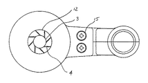
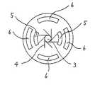
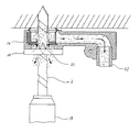
図3に示すラバーリング1はゴム等の弾性体で形成され、中心には、先端工具であるビット2の外径よりも、僅かに小さい径の挿通穴3を有し、挿通穴3の外周には放射状に延びるスリット4が形成されている。また、スリット4の外側には取付穴5と吸入口6が夫々設けてある。
The rubber ring 1 shown in FIG. 3 is formed of an elastic body such as rubber, and has an
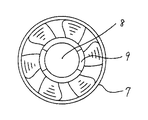
図4に示す樹脂製のファン7は、扇風機の羽根のように、中心から放射状に延びる多羽根で形成され、それ自体が回転することにより、一定の方向へ気流を発生させるものである。また、中心にはビット2が挿通する穴8が形成され、穴8周辺には突起9が形成されている。
The resin-made
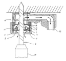
図1、図2において、回転体10は、ラバーリング1とファン7により構成され、突起9と取付穴5が嵌合し、接着固定されている。また、ファン7の外周は、後述するファンケース11の内径よりも、僅かに小さな径である。シール14は従来例で示した図5、図6と同様の形状で、中央の貫通穴19には、色々な径のビット2に対応できるよう、放射状に延びる切込み19を設けてあり、シール14は、吸塵覆16に固定されている。ファンケース11は円筒形状で、一端の中央には、ビット2の径よりも僅かに大きい、穴12を有し、他端は開口している。ファンケース11内部には、回転体10が収納され、中央にビット2の貫通穴を有するスペーサ13とシール14を介して、固定用ねじ15にて吸塵覆16に固着される。この時、回転体10は軸方向に対する移動を、ファンケース11内部に形成された突部17と、スペーサ13で制限される。
1 and 2, the rotating body 10 includes a rubber ring 1 and a
天井等の上向きでの穿孔時、穿孔機本体18に取付けられたビット2は、ファンケース11の穴12とラバーリング1の挿通穴3と、シール14の挿通穴19に挿通され、ビット2にラバーリング1とシール14が嵌着する。この時、ラバーリング1と、シール14の貫通穴19は、夫々広げられ、まくれた状態となる。ビット2を回転させ、穿孔を開始すると、シール14は吸塵覆16に固定されているので、回転しないが、回転体10は、ビット2外周とラバーリング1の挿通穴3間に作用する摩擦により、ビット2の回転に追従し、2,000〜5,000rpmの高速で回転する。これと同時に、回転体10を構成する、ファン7の多羽根が周囲の空気を高速で移動させ、図1に示すような吸入口6を通った経路の気流が発生する。この状態で、吸塵覆16のシール14に設けられた貫通穴19の切込み20の隙間21から粉塵が漏れ出そうとしても、上記した気流により、シール14内に押し戻され、吸塵覆16から漏れ出すことはない。よって、天井等の上向きでの穿孔時においても、粉塵が作業者へ落下しないことから、作業場を汚すことなく、快適な作業ができる。
At the time of drilling upward such as the ceiling, the bit 2 attached to the drilling machine
本発明では、回転体10をラバーリング1とファン7の2つの部品により構成したが、1つの部品で構成しても、その効果は同じである。
In the present invention, the rotating body 10 is composed of two parts, the rubber ring 1 and the
1はラバーリング、2はビット、3は挿通穴、4はスリット、5は取付穴、6は吸入口、7はファン、8は穴、9は突起、10は回転体、11はファンケース、12は穴、13はスペーサ、14はシール、15は固定用ねじ、16は吸塵覆、17は突部、18は本体、19は貫通穴、20は切込み、21は隙間、22は吸塵パイプである。
1 is a rubber ring, 2 is a bit, 3 is an insertion hole, 4 is a slit, 5 is a mounting hole, 6 is a suction port, 7 is a fan, 8 is a hole, 9 is a protrusion, 10 is a rotating body, 11 is a fan case, 12 is a hole, 13 is a spacer, 14 is a seal, 15 is a fixing screw, 16 is a dust cover, 17 is a projection, 18 is a body, 19 is a through hole, 20 is a cut, 21 is a gap, and 22 is a dust pipe. is there.
Claims (2)
The perforator according to claim 1, wherein the rotating body has a multi-blade shape.
Priority Applications (1)
| Application Number | Priority Date | Filing Date | Title |
|---|---|---|---|
| JP2004115506A JP2005297318A (en) | 2004-04-09 | 2004-04-09 | Drilling machine |
Applications Claiming Priority (1)
| Application Number | Priority Date | Filing Date | Title |
|---|---|---|---|
| JP2004115506A JP2005297318A (en) | 2004-04-09 | 2004-04-09 | Drilling machine |
Publications (1)
| Publication Number | Publication Date |
|---|---|
| JP2005297318A true JP2005297318A (en) | 2005-10-27 |
Family
ID=35329461
Family Applications (1)
| Application Number | Title | Priority Date | Filing Date |
|---|---|---|---|
| JP2004115506A Withdrawn JP2005297318A (en) | 2004-04-09 | 2004-04-09 | Drilling machine |
Country Status (1)
| Country | Link |
|---|---|
| JP (1) | JP2005297318A (en) |
Cited By (8)
| Publication number | Priority date | Publication date | Assignee | Title |
|---|---|---|---|---|
| US20090148248A1 (en) * | 2007-12-07 | 2009-06-11 | Hitachi Koki Co., Ltd. | Drilling tool with dust collector |
| JP2011005843A (en) * | 2009-05-29 | 2011-01-13 | Hitachi Koki Co Ltd | Drilling machine having dust collector |
| JP2013188856A (en) * | 2012-03-15 | 2013-09-26 | Fuji Heavy Ind Ltd | Device and method for driving drill |
| KR101515583B1 (en) * | 2013-12-05 | 2015-04-27 | 주식회사 비움 | A dust collector |
| CN105058595A (en) * | 2015-08-20 | 2015-11-18 | 无锡中强电碳有限公司 | Carbon-graphite rod tapping, processing and polishing device |
| KR101861188B1 (en) * | 2015-06-18 | 2018-05-28 | 주식회사 어반환경 | Sheet for preventing scattering for asbestos work |
| CN111673918A (en) * | 2020-07-09 | 2020-09-18 | 孙小猛 | A dust collector for decoration and punching |
| JP2021014013A (en) * | 2014-10-28 | 2021-02-12 | エンリンク アーエス | Portable robot drilling device and method of drilling ceilings and walls |
-
2004
- 2004-04-09 JP JP2004115506A patent/JP2005297318A/en not_active Withdrawn
Cited By (10)
| Publication number | Priority date | Publication date | Assignee | Title |
|---|---|---|---|---|
| US20090148248A1 (en) * | 2007-12-07 | 2009-06-11 | Hitachi Koki Co., Ltd. | Drilling tool with dust collector |
| US8529169B2 (en) * | 2007-12-07 | 2013-09-10 | Hitachi Koki Co., Ltd. | Drilling tool with dust collector |
| JP2011005843A (en) * | 2009-05-29 | 2011-01-13 | Hitachi Koki Co Ltd | Drilling machine having dust collector |
| JP2013188856A (en) * | 2012-03-15 | 2013-09-26 | Fuji Heavy Ind Ltd | Device and method for driving drill |
| KR101515583B1 (en) * | 2013-12-05 | 2015-04-27 | 주식회사 비움 | A dust collector |
| JP2021014013A (en) * | 2014-10-28 | 2021-02-12 | エンリンク アーエス | Portable robot drilling device and method of drilling ceilings and walls |
| JP7104125B2 (en) | 2014-10-28 | 2022-07-20 | ヒルティ コーポレーション | Portable robot drilling device and method of drilling ceilings and walls |
| KR101861188B1 (en) * | 2015-06-18 | 2018-05-28 | 주식회사 어반환경 | Sheet for preventing scattering for asbestos work |
| CN105058595A (en) * | 2015-08-20 | 2015-11-18 | 无锡中强电碳有限公司 | Carbon-graphite rod tapping, processing and polishing device |
| CN111673918A (en) * | 2020-07-09 | 2020-09-18 | 孙小猛 | A dust collector for decoration and punching |
Similar Documents
| Publication | Publication Date | Title |
|---|---|---|
| JP2005297318A (en) | Drilling machine | |
| WO2016129268A1 (en) | Dust suction drill and dust suction unit | |
| CN104907875B (en) | Wind-force elasticity is from advanceable vertically to lathe | |
| CN119408026A (en) | Disposable lunch box trimming device | |
| JP4014218B1 (en) | Rotary excavation tool and road surface excavator | |
| JP2013079625A (en) | Electric centrifugal blower and vacuum cleaner using the same | |
| CN112122630A (en) | Main shaft seal structure and tool turret | |
| JP5229682B2 (en) | Drilling tool | |
| JP4310353B2 (en) | Rotary excavation tool, road surface excavator and road surface excavation method | |
| JP2009125930A (en) | Dust suction device for hand tool device | |
| TW201723359A (en) | Processing machine main shaft and main shaft sealing apparatus for reducing the number of components and lowering the manufacturing cost | |
| JP2013126324A (en) | Oil mist intercepting device for generator bearings | |
| JP4992624B2 (en) | Electric tool | |
| JPH0632248Y2 (en) | Perforator dust collector | |
| CN206588442U (en) | A kind of pellet process equipment for chamfering | |
| CN111211664B (en) | High-speed rotating magnetic fluid transmission device for etching machine | |
| JP2005270245A (en) | Dishwasher washing and drainage pump | |
| CN219991951U (en) | Tool bit assembly of hair bulb trimmer | |
| CN223374668U (en) | Fan structure | |
| CN223984608U (en) | An oil sealing structure and a fan | |
| JP2011136493A (en) | Drilling machine with dust collector | |
| CN220988578U (en) | A knife disc shock-absorbing structure and wall-breaking machine | |
| JPH1110638A (en) | Dust collecting cup of boring tool | |
| CN211573845U (en) | A fan that is easy to install and has an anti-backflow function | |
| JPH0351352Y2 (en) |
Legal Events
| Date | Code | Title | Description |
|---|---|---|---|
| A621 | Written request for application examination |
Effective date: 20070328 Free format text: JAPANESE INTERMEDIATE CODE: A621 |
|
| A761 | Written withdrawal of application |
Effective date: 20090206 Free format text: JAPANESE INTERMEDIATE CODE: A761 |