JP2005297316A - Insert holder - Google Patents
Insert holder Download PDFInfo
- Publication number
- JP2005297316A JP2005297316A JP2004115420A JP2004115420A JP2005297316A JP 2005297316 A JP2005297316 A JP 2005297316A JP 2004115420 A JP2004115420 A JP 2004115420A JP 2004115420 A JP2004115420 A JP 2004115420A JP 2005297316 A JP2005297316 A JP 2005297316A
- Authority
- JP
- Japan
- Prior art keywords
- insert
- holding
- mounting member
- holding portion
- tip
- Prior art date
- Legal status (The legal status is an assumption and is not a legal conclusion. Google has not performed a legal analysis and makes no representation as to the accuracy of the status listed.)
- Pending
Links
- 238000003780 insertion Methods 0.000 description 16
- 230000037431 insertion Effects 0.000 description 16
- 230000002093 peripheral effect Effects 0.000 description 10
- 238000009415 formwork Methods 0.000 description 5
- 238000003466 welding Methods 0.000 description 2
- 206010044565 Tremor Diseases 0.000 description 1
- 239000000428 dust Substances 0.000 description 1
- 238000000034 method Methods 0.000 description 1
- 239000011347 resin Substances 0.000 description 1
- 229920005989 resin Polymers 0.000 description 1
- 239000007787 solid Substances 0.000 description 1
- XLYOFNOQVPJJNP-UHFFFAOYSA-N water Substances O XLYOFNOQVPJJNP-UHFFFAOYSA-N 0.000 description 1
Images
Landscapes
- Lining And Supports For Tunnels (AREA)
- Moulds, Cores, Or Mandrels (AREA)
- Manufacturing Of Tubular Articles Or Embedded Moulded Articles (AREA)
Abstract
Description
本発明は、例えば、コンクリート製セグメント内に埋設されるインサートを保持するインサートホルダーに関する。 The present invention relates to an insert holder that holds an insert embedded in, for example, a concrete segment.
セグメント内側面に二次覆工としてライニング等が取り付けられる場合、セグメントの内側面には、ライニングを取り付けるためのインサートを設ける必要がある。コンクリート製のセグメントにインサートを設けるには、セグメントのコンクリートを打設する際に予め型枠内にインサートを配置しておき、インサートがセットされた状態でコンクリート打設を行い、セグメント内にインサートを埋設させる。このとき、インサートを型枠内の一定位置に保持するインサートホルダーが用いられる。 When a lining or the like is attached to the inner side surface of the segment as a secondary lining, it is necessary to provide an insert for attaching the lining on the inner side surface of the segment. To install an insert in a concrete segment, place the insert in the formwork in advance when placing the concrete in the segment, place the insert in the set state, and place the insert in the segment. To be buried. At this time, an insert holder that holds the insert at a fixed position in the mold is used.
インサートホルダーには、型枠に設けられた筒状の取付部材と、取付部材に取り付けられるとともにインサートが仮装着されるインサート保持部材とが備えられている。インサート保持部材は、一端にインサートに螺合されるネジ部が形成され、他端に取付部材の挿入孔に挿装される円柱形の保持部が形成されている。従来、保持部の先端には、側方に突出する一対の係止部が形成されており、取付部材の挿入孔内周面には軸方向に延在する一対の溝部が形成されている。保持部を取付部材内に挿装させる際、保持部先端の係止部が溝部内に嵌入するように保持部を取付部材内に挿入し、保持部の先端が取付部材内を貫通して係止部が突出された時点で保持部を軸回転させる。これによって、係止部は取付部材端面に係止され、取付部材に取り付けられたインサート保持部材の引き抜け防止を図ることができる(例えば、特許文献1参照。)。
しかしながら、上記した従来のインサートホルダーでは、インサート保持部材は保持部を軸回転させて係止部を溝部位置からずらすことで取付部材に係止しているため、何かの衝撃でインサート保持部材が回転し、係止部が溝部位置まで移動した場合、インサート保持部材が取付部材から外れる虞があるという問題が存在する。また、保持部を取付部材内に押し込んだ後に取付部材の挿入孔内で保持部を軸回転させるため、取付部材の挿入孔内周面と保持部の外周面との間には回転させるための隙間が必要であり、取付部材に挿装されたインサート保持部材のがたつきが大きいという問題が存在する。 However, in the above-described conventional insert holder, the insert holding member is locked to the mounting member by rotating the holding portion about the axis and shifting the locking portion from the groove portion position. When it rotates and a latching | locking part moves to a groove part position, there exists a problem that there exists a possibility that an insert holding member may remove | deviate from an attachment member. In addition, since the holding portion is axially rotated in the insertion hole of the mounting member after the holding portion is pushed into the mounting member, the holding portion is rotated between the inner peripheral surface of the insertion hole and the outer peripheral surface of the holding portion. There is a problem that a gap is necessary, and that the insert holding member inserted into the mounting member has a large rattling.
本発明は、上記した従来の問題が考慮されたものであり、インサート保持部材が型枠に設けられた取付部材から外れ難く、取付部材に挿装された状態でのがたつきを抑えることができるインサートホルダーを提供することを目的としている。 In the present invention, the above-described conventional problems are taken into consideration, and the insert holding member is not easily detached from the mounting member provided on the mold, and it is possible to suppress rattling in a state in which the insert holding member is inserted into the mounting member. It aims to provide an insert holder that can be used.
請求項1記載の発明は、型枠に設けられた筒状の取付部材と、該取付部材内に挿装される保持部が形成されたインサート保持部材とが備えられているインサートホルダーにおいて、前記保持部には、該保持部の先端から軸方向に延在するスリットが形成され、前記保持部の先端には、前記取付部材に係止される係止部が形成されていることを特徴としている。 The invention according to claim 1 is an insert holder provided with a cylindrical mounting member provided in a mold and an insert holding member in which a holding portion to be inserted into the mounting member is formed. The holding portion is formed with a slit extending in the axial direction from the tip of the holding portion, and a locking portion that is locked to the mounting member is formed at the tip of the holding portion. Yes.
このような特徴により、筒状の取付部材内に保持部を挿入するとき、保持部先端の係止部が取付部材の内周面上を摺動しつつ、スリットが形成された保持部は内側に窄まり、係止部が取付部材を貫通したとき、スリットが形成された保持部は外側に広がり、係止部が取付部材に係止される。 Due to such a feature, when the holding portion is inserted into the cylindrical mounting member, the holding portion where the slit is formed is inward while the engaging portion at the tip of the holding portion slides on the inner peripheral surface of the mounting member. When the locking part penetrates the mounting member, the holding part in which the slit is formed spreads outward and the locking part is locked to the mounting member.
本発明に係るインサートホルダーによれば、型枠に設けられた筒状の取付部材内に挿装される保持部には、先端から軸方向に延在するスリットが形成され、保持部の先端には、取付部材に係止される係止部が設けられており、保持部を挿入するとき、スリットが形成された保持部は内側に窄まり、係止部が取付部材を貫通したとき、スリットが形成された保持部は外側に広がって係止部が取付部材に係止されるため、一旦取付部材に挿装された保持部は抜け難く、インサート保持部材が回転したとしても取付部材から外れることはない。また、スリットが形成された保持部が外側に広がった状態で取付部材に挿装されるため、スリットが形成された保持部が取付部材の内周面を押圧し、取付部材に挿装されたインサート保持部材のがたつきを抑えることができる。 According to the insert holder according to the present invention, a slit extending in the axial direction from the tip is formed in the holding portion that is inserted into the cylindrical mounting member provided in the mold, and is formed at the tip of the holding portion. Is provided with a locking portion that is locked to the mounting member, and when the holding portion is inserted, the holding portion in which the slit is formed is narrowed inward, and when the locking portion penetrates the mounting member, the slit is formed. Since the holding portion formed with is spread outward and the locking portion is locked to the mounting member, the holding portion once inserted in the mounting member is difficult to come off, and even if the insert holding member rotates, it is detached from the mounting member. There is nothing. Further, since the holding portion in which the slit is formed is inserted into the mounting member in a state of spreading outward, the holding portion in which the slit is formed presses the inner peripheral surface of the mounting member and is inserted into the mounting member. Shaking of the insert holding member can be suppressed.
以下、本発明に係るインサートホルダーの実施の形態について、図面に基いて説明する。 Hereinafter, embodiments of an insert holder according to the present invention will be described with reference to the drawings.
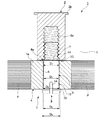
図1は、インサートホルダーを用いたインサート取付構造を表す断面図である。図1において、符号Pはセグメント用型枠であり、コンクリート製のセグメントSの内側面を形成する型枠である。この型枠Pには、インサート2をセグメントS内に埋設させるためのインサート取付構造1が形成されており、インサート取付構造1は、インサート2と、型枠P内の所定位置にインサート2を保持するインサートホルダー3とから構成されている。インサートホルダー3は、型枠Pに設けられた取付部材4と、取付部材4内に取り付けられるとともにインサート2に螺合され、インサート2を保持するインサート保持部材5とから構成されている。
FIG. 1 is a sectional view showing an insert mounting structure using an insert holder. In FIG. 1, the code | symbol P is a formwork for segments and is a formwork which forms the inner surface of the segment S made from concrete. An insert mounting structure 1 for embedding the
インサート2の一端面は、セグメントSの内側面と面一に形成されており、インサート2の内部には、セグメントSの内側に開放されて二次覆工のライニング等が取り付けられる雌ネジ孔2aが形成されている。また、インサート2の他端にはコンクリート製のセグメントS内に定着する定着部2bが形成されている。取付部材4は、型枠Pに形成された貫通孔1aに嵌合されており、溶接等によって型枠Pに固定されている。取付部材4は、円筒状に形成されており、その中心には軸方向に延在する挿通孔6が形成されている。セグメントS内側面に対向する挿通孔6の入口部6aは外側(セグメントS側)に向かって広げられており、入口部6aの角は丸みを帯びて滑らかに形成されている。
One end surface of the
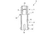
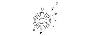
図2はインサート保持部材5の断面図であり、図3は図1における下側からインサート保持部材5をみた投影図である。図1,図2,図3に示すように、インサート保持部材5は、樹脂から成形された筒状の成形品であり、外周にねじ山が切られてインサート2の雌ネジ孔2aに螺合される雄ネジ部7と、取付部材4の挿通孔6に挿装される保持部8とから構成されている。雄ネジ部7の孔9は、断面形状が六角形に形成されており、図示せぬ六角レンジ等が嵌入される。なお、この孔9の断面形状は、工具を嵌合させて雄ネジ部7を回転させることができる形状であれば、六角形に限らず四角形等でもよい。また、雄ネジ部7の孔9内には、インサート2の雌ネジ孔2a内への塵や水の浸入を防ぐ遮蔽板10が形成されている。雄ネジ部7の基端部(保持部8側の端部)には、インサート2と取付部材4との間に介在される円状の鍔部11が張設されている。
2 is a cross-sectional view of the
保持部8は円柱形の孔16が形成された円筒形のものであり、保持部8中間部の外径D0は取付部材4の挿通孔6の内径D1と略同程度に形成されており、保持部8が挿通孔6内に挿通されたときのクリアランスは0.1mm〜0.2mm程度である。保持部8の先端部には、先端に向かってテーパー状に広がる拡径部12が形成されており、拡径部12の先端の径D2は、保持部8中間部の径D0よりも大きい。また、保持部8(拡径部12)の先端には、取付部材4の端面に係止される鍔状の係止部13が形成されている。係止部13は、保持部8の外周面から側方に張り出されており、係止部13の基端の径D3は、挿通孔6の内径D1や拡径部12先端の径D2よりも大きい。また、係止部13は、先端に向かってテーパー状に窄まる形状に形成されており、係止部13の先端の径D4は、保持部8中間部の径D0よりも若干小さい。
The
また、保持部8には、保持部8(係止部13)の先端から拡径部12の基端にかけて軸方向に延在する一対のスリット14が形成されている。一対のスリット14は、互いに対向する位置に形成されており、保持部8の先端は2つに分割されている。
The
保持部8の基端(雄ネジ部7側の端部)には、周方向へわたって切り込み部15が形成されており、端部外周面が内側に窄まっている。切り込み部15は、保持部8中間部よりも肉厚が薄く形成されており、適度な力で破断するように形成されている。切り込み部15の肉厚は、0.5mm〜1.0mm程度であり、0.8mmが好ましい。
A
次に、上記した構成からなるインサートホルダー3の使用方法について説明する。
Next, the usage method of the
まず、型枠Pに予め形成された貫通孔1aに取付部材4を嵌合させる。このとき、取付部材4と型枠Pとは溶接等によって強固に固定する。一方、インサート2の雌ネジ孔2aにインサート保持部材5の雄ネジ部7を螺合させて、インサート保持部材5にインサート2を取り付ける。このとき、鍔部11がセグメントSの内側面と面一になるインサート2の一端面に当接するところまで雄ネジ部7を螺合させる。
First, the attachment member 4 is fitted into the through
次に、インサート2が螺合されたインサート保持部材5を取付部材4に取り付ける。具体的には、まず、保持部8を取付部材4の挿通孔6内に入口部6aから挿入し、そのまま係止部13が挿通孔6から出るところまで軸方向に押し込む。このとき、広げられた入口部6aの位置に径の小さい係止部13の先端を合わせ、丸く滑らかに形成された入口部6aの角上にテーパー状の係止部13の外周面が摺動する。また、係止部13が挿通孔6の内周面に押圧されて、拡径部12および係止部13が形成された保持部8の先端は窄まる。また、係止部13が挿通孔6から出ると、窄まっていた保持部8の先端は弾性により元の状態に戻り、挿通孔6よりも広がる。以上で、インサート2は、型枠P内の所定位置に保持される。なお、コンクリート打設後に型枠Sの脱型を行うと、切り込み部15のところで破断し、保持部8と雄ネジ部7とが分離する。そして、インサート2内に残った雄ネジ部7は、孔9に六角レンジ等を嵌入して撤去する。
Next, the
上記した構成からなるインサートホルダー3によれば、保持部を挿入するとき、スリット14が形成された保持部8の先端は内側に窄まり、係止部13が取付部材4を貫通したとき、保持部8の先端は外側に広がって係止部13が取付部材4に係止されるため、一旦取付部材4に挿装された保持部8は抜け難く、インサート保持部材5が回転したとしても取付部材4から外れることはない。また、スリット14が形成された保持部8(拡幅部12)が外側に広がった状態で取付部材4に挿装され、拡幅部12が挿通孔6の内周面を押圧するため、取付部材4に挿装されたインサート保持部材5のがたつきを抑えることができる。
According to the
以上、本発明に係るインサートホルダーの実施の形態について説明したが、本発明は上記した実施の形態に限定されるものではなく、その趣旨を逸脱しない範囲で適宜変更可能である。例えば、上記した実施の形態では、インサートホルダー3を用いてインサート2を保持してセグメントS内にインサート2を埋設しているが、本発明は、セグメントSに限らず、コンクリート製床版やその他のコンクリート部材などにインサートを埋設する場合に用いてもよい。
As mentioned above, although embodiment of the insert holder concerning this invention was described, this invention is not limited to above-described embodiment, In the range which does not deviate from the meaning, it can change suitably. For example, in the above-described embodiment, the
また、上記した実施の形態では、保持部8の先端から拡径部12の基端にかけて軸方向に延在する一対のスリット14が形成されており、保持部8の先端が2つに分割されているが、本発明は、スリットを3本形成して保持部の先端を3分割にしてもよく、スリットの数に限定されるものではない。また、スリットの長さは適宜変更可能であり、係止部のところだけでも良く、保持部全長にわたって形成してもよい。
In the embodiment described above, a pair of
また、上記した実施の形態では、保持部8は筒状に形成されており、内部が中空に形成されているが、本発明は、保持部の内部が中実に形成されてもよい。これによって、保持部は破損し難くなる。
Further, in the above-described embodiment, the holding
3 インサートホルダー
4 取付部材
5 インサート保持部材
8 保持部
13 係止部
14 スリット
P 型枠
3 Insert holder 4
Claims (1)
前記保持部には、該保持部の先端から軸方向に延在するスリットが形成され、前記保持部の先端には、前記取付部材に係止される係止部が形成されていることを特徴とするインサートホルダー。
In an insert holder provided with a cylindrical mounting member provided in a mold and an insert holding member formed with a holding portion to be inserted into the mounting member,
The holding portion is formed with a slit extending in the axial direction from the tip of the holding portion, and a locking portion that is locked to the mounting member is formed at the tip of the holding portion. Insert holder.
Priority Applications (1)
| Application Number | Priority Date | Filing Date | Title |
|---|---|---|---|
| JP2004115420A JP2005297316A (en) | 2004-04-09 | 2004-04-09 | Insert holder |
Applications Claiming Priority (1)
| Application Number | Priority Date | Filing Date | Title |
|---|---|---|---|
| JP2004115420A JP2005297316A (en) | 2004-04-09 | 2004-04-09 | Insert holder |
Publications (1)
| Publication Number | Publication Date |
|---|---|
| JP2005297316A true JP2005297316A (en) | 2005-10-27 |
Family
ID=35329459
Family Applications (1)
| Application Number | Title | Priority Date | Filing Date |
|---|---|---|---|
| JP2004115420A Pending JP2005297316A (en) | 2004-04-09 | 2004-04-09 | Insert holder |
Country Status (1)
| Country | Link |
|---|---|
| JP (1) | JP2005297316A (en) |
Cited By (2)
| Publication number | Priority date | Publication date | Assignee | Title |
|---|---|---|---|---|
| JP2014009480A (en) * | 2012-06-28 | 2014-01-20 | Taisei Corp | Concrete member manufacturing method |
| JP7632838B2 (en) | 2020-12-28 | 2025-02-19 | フジミ工研株式会社 | Structure for retaining embedded members in formwork for manufacturing precast concrete products and method for attaching embedded members |
Citations (4)
| Publication number | Priority date | Publication date | Assignee | Title |
|---|---|---|---|---|
| JPH11348023A (en) * | 1998-06-08 | 1999-12-21 | Somic Ishikawa:Kk | Connecting implement for formwork and formwork device |
| JP2000084913A (en) * | 1998-09-11 | 2000-03-28 | Ishikawajima Constr Materials Co Ltd | Form for segment |
| JP2000254908A (en) * | 1999-01-06 | 2000-09-19 | Ooike:Kk | Concrete embedded article, holder for mounting, form and production of concrete product |
| JP2001138310A (en) * | 1999-11-15 | 2001-05-22 | Kana Flex Corporation Kk | Method for manufacturing insert holder and molding |
-
2004
- 2004-04-09 JP JP2004115420A patent/JP2005297316A/en active Pending
Patent Citations (4)
| Publication number | Priority date | Publication date | Assignee | Title |
|---|---|---|---|---|
| JPH11348023A (en) * | 1998-06-08 | 1999-12-21 | Somic Ishikawa:Kk | Connecting implement for formwork and formwork device |
| JP2000084913A (en) * | 1998-09-11 | 2000-03-28 | Ishikawajima Constr Materials Co Ltd | Form for segment |
| JP2000254908A (en) * | 1999-01-06 | 2000-09-19 | Ooike:Kk | Concrete embedded article, holder for mounting, form and production of concrete product |
| JP2001138310A (en) * | 1999-11-15 | 2001-05-22 | Kana Flex Corporation Kk | Method for manufacturing insert holder and molding |
Cited By (2)
| Publication number | Priority date | Publication date | Assignee | Title |
|---|---|---|---|---|
| JP2014009480A (en) * | 2012-06-28 | 2014-01-20 | Taisei Corp | Concrete member manufacturing method |
| JP7632838B2 (en) | 2020-12-28 | 2025-02-19 | フジミ工研株式会社 | Structure for retaining embedded members in formwork for manufacturing precast concrete products and method for attaching embedded members |
Similar Documents
| Publication | Publication Date | Title |
|---|---|---|
| JP2010249198A (en) | Fixture and fixing structure of installation object member | |
| TWI542795B (en) | Drop-in anchor and drop-in anchor systems | |
| JP3864140B2 (en) | Expansion anchor for fixing to plate-like building materials | |
| JP2010522019A5 (en) | ||
| JP5619748B2 (en) | Fastening device | |
| JP2004028244A (en) | Clip and member coupler | |
| JP2010043728A (en) | Screw grommet | |
| JP2005114169A (en) | Support bolt joint | |
| JP2005297316A (en) | Insert holder | |
| US20070160418A1 (en) | Quick assembly bolt jacket | |
| KR100466870B1 (en) | Spacing fixture of concrete form | |
| JP2008180340A (en) | Nail for concrete | |
| JP5908798B2 (en) | CONNECTING DEVICE AND CONCRETE MEMBER CONNECTING DEVICE USING THE SAME | |
| JP5908797B2 (en) | CONNECTING DEVICE AND CONCRETE MEMBER CONNECTING DEVICE USING THE SAME | |
| JP2005325948A (en) | Bolt unit | |
| JP2013221568A (en) | Fastening fixed member | |
| CN111433987B (en) | Mounting sleeve | |
| KR20150103491A (en) | Improved set anchor bolt | |
| JP6696705B2 (en) | Water diversion core mounting device | |
| JP5187887B2 (en) | Alarm | |
| JP2010084928A (en) | Connecting implement | |
| KR200330464Y1 (en) | Anker assembly | |
| KR200281485Y1 (en) | Spacing fixture of concrete form | |
| KR200401075Y1 (en) | Device for fixing form panel | |
| JP2013540960A (en) | Expansion anchor |
Legal Events
| Date | Code | Title | Description |
|---|---|---|---|
| A621 | Written request for application examination |
Free format text: JAPANESE INTERMEDIATE CODE: A621 Effective date: 20070308 |
|
| A131 | Notification of reasons for refusal |
Free format text: JAPANESE INTERMEDIATE CODE: A131 Effective date: 20100316 |
|
| A02 | Decision of refusal |
Free format text: JAPANESE INTERMEDIATE CODE: A02 Effective date: 20100713 |