JP2005297210A - Resin molded article and method for manufacturing the same - Google Patents
Resin molded article and method for manufacturing the same Download PDFInfo
- Publication number
- JP2005297210A JP2005297210A JP2004112134A JP2004112134A JP2005297210A JP 2005297210 A JP2005297210 A JP 2005297210A JP 2004112134 A JP2004112134 A JP 2004112134A JP 2004112134 A JP2004112134 A JP 2004112134A JP 2005297210 A JP2005297210 A JP 2005297210A
- Authority
- JP
- Japan
- Prior art keywords
- resin molded
- resistance value
- molded product
- carbon
- skin
- Prior art date
- Legal status (The legal status is an assumption and is not a legal conclusion. Google has not performed a legal analysis and makes no representation as to the accuracy of the status listed.)
- Granted
Links
- 229920005989 resin Polymers 0.000 title claims abstract description 73
- 239000011347 resin Substances 0.000 title claims abstract description 73
- 238000004519 manufacturing process Methods 0.000 title claims description 8
- 238000000034 method Methods 0.000 title description 7
- OKTJSMMVPCPJKN-UHFFFAOYSA-N Carbon Chemical compound [C] OKTJSMMVPCPJKN-UHFFFAOYSA-N 0.000 claims abstract description 53
- 229910052799 carbon Inorganic materials 0.000 claims abstract description 45
- 239000002086 nanomaterial Substances 0.000 claims abstract description 39
- 238000002347 injection Methods 0.000 claims description 42
- 239000007924 injection Substances 0.000 claims description 42
- 238000001746 injection moulding Methods 0.000 claims description 13
- 239000003575 carbonaceous material Substances 0.000 abstract description 7
- 238000002156 mixing Methods 0.000 abstract description 6
- 230000001788 irregular Effects 0.000 abstract description 3
- 238000002474 experimental method Methods 0.000 description 19
- 210000003491 skin Anatomy 0.000 description 17
- VNWKTOKETHGBQD-UHFFFAOYSA-N methane Chemical compound C VNWKTOKETHGBQD-UHFFFAOYSA-N 0.000 description 12
- 239000000463 material Substances 0.000 description 11
- 238000010586 diagram Methods 0.000 description 10
- 239000002134 carbon nanofiber Substances 0.000 description 9
- 238000009413 insulation Methods 0.000 description 9
- 210000002615 epidermis Anatomy 0.000 description 6
- 239000004743 Polypropylene Substances 0.000 description 5
- 230000005611 electricity Effects 0.000 description 5
- 229910021392 nanocarbon Inorganic materials 0.000 description 5
- -1 polypropylene Polymers 0.000 description 5
- 229920001155 polypropylene Polymers 0.000 description 5
- 238000009826 distribution Methods 0.000 description 4
- 239000000835 fiber Substances 0.000 description 4
- 238000005259 measurement Methods 0.000 description 4
- 230000003068 static effect Effects 0.000 description 4
- 238000012360 testing method Methods 0.000 description 4
- 229920000049 Carbon (fiber) Polymers 0.000 description 3
- 239000004917 carbon fiber Substances 0.000 description 3
- 125000004432 carbon atom Chemical group C* 0.000 description 2
- 229910021393 carbon nanotube Inorganic materials 0.000 description 2
- 239000002041 carbon nanotube Substances 0.000 description 2
- 229910003460 diamond Inorganic materials 0.000 description 2
- 239000010432 diamond Substances 0.000 description 2
- 230000000694 effects Effects 0.000 description 2
- 239000010439 graphite Substances 0.000 description 2
- 229910002804 graphite Inorganic materials 0.000 description 2
- 239000011810 insulating material Substances 0.000 description 2
- 239000000126 substance Substances 0.000 description 2
- 229920005992 thermoplastic resin Polymers 0.000 description 2
- 239000004677 Nylon Substances 0.000 description 1
- 239000011203 carbon fibre reinforced carbon Substances 0.000 description 1
- 239000013078 crystal Substances 0.000 description 1
- 230000007423 decrease Effects 0.000 description 1
- 238000001125 extrusion Methods 0.000 description 1
- 239000011888 foil Substances 0.000 description 1
- 230000005484 gravity Effects 0.000 description 1
- 230000017525 heat dissipation Effects 0.000 description 1
- 238000010438 heat treatment Methods 0.000 description 1
- 230000001771 impaired effect Effects 0.000 description 1
- 239000002184 metal Substances 0.000 description 1
- 238000000465 moulding Methods 0.000 description 1
- 229920001778 nylon Polymers 0.000 description 1
- 238000007747 plating Methods 0.000 description 1
- 238000003825 pressing Methods 0.000 description 1
- 230000035945 sensitivity Effects 0.000 description 1
- 238000012546 transfer Methods 0.000 description 1
Images



Landscapes
- Injection Moulding Of Plastics Or The Like (AREA)
Abstract
Description
本発明は、熱伝導率の大きなカーボンナノ材料を樹脂に混合して製造する樹脂成形品及びその製造技術に関するものである。 The present invention relates to a resin molded product produced by mixing a carbon nanomaterial having a high thermal conductivity with a resin, and a production technique thereof.
電気部品や電子部品を収納する筐体は、金属や樹脂で製造される。近年は、絶縁性及び成形性に優れ、安価であることから、樹脂が筐体の主流となってきた。しかし、性能向上に伴って内蔵する電気・電子部品からの発熱量が増大する傾向にある。 A housing for storing electrical parts and electronic parts is made of metal or resin. In recent years, resin has become the mainstream of casings because it is excellent in insulation and moldability and is inexpensive. However, as the performance improves, the amount of heat generated from the built-in electric / electronic components tends to increase.
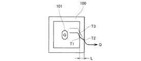
図11は筐体の温度分布図であり、筐体100にパワートランスなどの発熱部品101を内蔵した原理図を示す。今、筐体100の壁の厚さをL、同熱伝導率をλ1、発熱部品101の放熱量をQとすれば、Q=(λ1/L)・S・(ΔT)と表すことができる。なお、Sは壁の面積、ΔTは壁の内面と外面の温度差である。
FIG. 11 is a temperature distribution diagram of the housing, and shows a principle diagram in which the
熱伝導率がλ1のときに、実線で示す温度曲線を描くことができ、壁の内面の温度はT1、外面の温度はT2であったとする。ΔT=(T1−T2)となる。 When the thermal conductivity is λ1, a temperature curve indicated by a solid line can be drawn, and the temperature of the inner surface of the wall is T1, and the temperature of the outer surface is T2. ΔT = (T1−T2).
次に、材質などを変更した別の筐体について検討する。ただし、寸法は変更しない。
壁の熱伝導率はλ2(ただし、λ2<λ1)であり、壁の内面の温度はT3であったとする。壁の材質の変更前後において、発熱量Q、壁の外面の温度T2は同一とする。
Next, consider another case with a different material. However, the dimensions are not changed.
It is assumed that the thermal conductivity of the wall is λ2 (where λ2 <λ1), and the temperature of the inner surface of the wall is T3. The heating value Q and the temperature T2 of the outer surface of the wall are the same before and after the change of the wall material.
すると、Q=(λ1/L)・S・(T1−T2)=(λ2/L)・S・(T3−T2)の等式が成立し、第2式及び第3式を整理すると、λ1・(T1−T2)=λ2・(T3−T2)となる。λ2<λ1であるから、(T1−T2)<(T3−T2)となり、T1<T3となる。T3に係る温度曲線を、想像線で示した。 Then, the equation Q = (λ1 / L) · S · (T1−T2) = (λ2 / L) · S · (T3−T2) holds, and when the second and third equations are arranged, λ1 (T1-T2) = λ2 · (T3-T2) Since λ2 <λ1, (T1-T2) <(T3-T2) and T1 <T3. The temperature curve relating to T3 is indicated by an imaginary line.
すなわち、熱伝導率λが小さいと壁の内面の温度が上昇する。この結果、筐体100の内部温度が高まり、発熱部品101の温度が高まり、発熱部品101の耐久性に問題が生じる。
したがって、筐体の熱対策として、壁の熱伝導率λを上げることが有効となる。
That is, when the thermal conductivity λ is small, the temperature of the inner surface of the wall increases. As a result, the internal temperature of the
Therefore, it is effective to increase the thermal conductivity λ of the wall as a heat countermeasure for the housing.
樹脂製壁の熱伝導率λを上げるには、樹脂に熱伝導率の高い物質を混ぜることが考えられる。熱伝導率の高い物質の一つにカーボン材料が上げられる。 In order to increase the thermal conductivity λ of the resin wall, it is conceivable to mix a resin with a high thermal conductivity. Carbon material is one of the substances with high thermal conductivity.
樹脂にカーボン材料を混ぜることで成形品の熱伝導性を高める技術が提案されている(例えば、特許文献1参照。)。
特許文献1の請求項1第4行〜第5行に「・・・造粒した炭素繊維と黒鉛を含有する熱可塑性樹脂を射出成形又は押出成形し、・・・」と記載され、同段落番号[0028]第5行〜第7行に「・・・熱伝導度が0.15Kcal/m・Hr・℃以上、比重2以下の熱可塑性樹脂発熱成形品が得られる効果がある。」と記載されている。 Claims 1 to 4 to 5 of Patent Document 1 are described as "... injection molding or extrusion molding of a granulated carbon fiber and a thermoplastic resin containing graphite, ..." Number [0028] Lines 5 to 7 have an effect that “... a thermoplastic resin exothermic molded article having a thermal conductivity of 0.15 Kcal / m · Hr · ° C. or more and a specific gravity of 2 or less is obtained”. Has been described.
しかし、熱伝導度を上げるために炭素繊維や黒鉛を増加すると、この増加に伴って導電性が増大し、樹脂の利点の一つである「絶縁性」が損なわれる。この結果、筐体の内面に絶縁シートを貼るなどの対策が必要になる。 However, when carbon fiber and graphite are increased in order to increase the thermal conductivity, the conductivity increases with this increase, and “insulation” which is one of the advantages of the resin is impaired. As a result, measures such as attaching an insulating sheet to the inner surface of the housing are required.
本発明は、樹脂成形品において、カーボン材料を混入することで熱伝導率を高めるとともに、絶縁性を維持することができる技術を提供することを課題とする。 This invention makes it a subject to provide the technique which can maintain insulation while improving heat conductivity by mixing a carbon material in a resin molded product.
ところで、電気部品や電子部品を収納する筐体は、表面に静電気が溜まらないようにする必要がある。しかし、樹脂製筐体は静電気が溜まりやすい。この対策として、樹脂製筐体の表皮に弱い導電性を付加する方法がある。弱い導電性を付加するためにメッキや箔を貼り付けると、コストが嵩むなど新たな問題が発生する。 By the way, it is necessary to prevent static electricity from accumulating on the surface of a housing for storing electrical components and electronic components. However, static electricity tends to accumulate in the resin casing. As a countermeasure, there is a method of adding weak conductivity to the skin of the resin casing. If plating or foil is applied to add weak conductivity, new problems such as increased costs arise.
本発明者らは、導電性及び熱伝導性を付与するために樹脂に黒鉛粉を混入する従来技術に着目した。しかし、黒鉛粉は樹脂にほぼ均一に分散するため、表皮だけ黒鉛粉の割合を減少させることはできなかった。 The present inventors paid attention to the prior art in which graphite powder is mixed into a resin in order to impart electrical conductivity and thermal conductivity. However, since the graphite powder is dispersed almost uniformly in the resin, it was not possible to reduce the ratio of the graphite powder only to the skin.
そこで、本発明者らは、黒鉛粉より格段に軽く、小さければ、この微細な物質を樹脂に不均等に分散させ得るのではないかと考え、微細な物質として、近年注目されてきたカーボンナノ材料を検討することにした。 Therefore, the present inventors thought that if this material was much lighter and smaller than graphite powder, this fine material could be dispersed unevenly in the resin, and carbon nanomaterials that have been attracting attention as a fine material in recent years. Decided to consider.
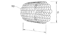
図1はカーボンナノファイバのモデル図であり、カーボンナノ材料の一種であるカーボンナノファイバ110は、六角網目状に配列した炭素原子のシートを筒状に巻いた形態のものであり、直径Dが1.0nm(ナノメートル)〜150nmであり、ナノレベルであるため、カーボンナノファイバ、カーボンナノ材料又はカーボンナノチューブと呼ばれる。なお、長さLは数μm〜100μmである。
FIG. 1 is a model diagram of a carbon nanofiber. A
炭素原子が立方格子状に並んだものがダイヤモンドであって、ダイヤモンドは極めて硬い物質である。カーボンナノファイバ110は、ダイヤモンドと同様に規則的な結晶構造を有するために機械的強度は大きい。また、炭素は電気をよく通すため、電極などに用いられる。
A diamond is a very hard substance in which carbon atoms are arranged in a cubic lattice. Since the
本発明者らは、カーボンナノ材料を含む樹脂成形品の研究を進める中で、次のような考えに至った。
カーボンナノ材料が通常の炭素材料と比較して極く微細で且つ軽いため、キャビティに溶融樹脂を充満させる過程で、流れの影響を敏感に受けて、カーボンナノ材料が樹脂に不均等に分散する可能性がある。
The inventors of the present invention have come up with the following idea while researching resin molded products containing carbon nanomaterials.
Since carbon nanomaterials are extremely fine and light compared to normal carbon materials, carbon nanomaterials are unevenly dispersed in the resin due to the sensitivity of flow during the process of filling the cavity with molten resin there is a possibility.
そこで、本発明者らは電気抵抗値と熱伝導度とを知るために、以下の実験を行った。
・材料:ナイロン80質量%+ナノカーボンファイバ20質量%
・樹脂成形品の大きさ:60mm×60mm
・樹脂成形品の厚さ:2mm
・射出速度:5mm/秒、100mm/秒、300mm/秒
Therefore, the present inventors conducted the following experiment in order to know the electric resistance value and the thermal conductivity.
・ Material:
-Resin molded product size: 60mm x 60mm
・ Thickness of resin molded product: 2mm
・ Injection speed: 5 mm / sec, 100 mm / sec, 300 mm / sec
図2は樹脂成形品の斜視図であり、樹脂成形品10は、例えば、Aが60mm、Bが60mm、Cが2mmの正方形板である。
図3は電気抵抗値測定図であり、樹脂成形品10を2枚のカーボン端子11、11で挟み、これらのカーボン端子11、11を介してインピーダンスアナライザで樹脂成形品10の厚さ方向における交流の電気抵抗値を計測する。カーボン端子11は10mm×10mmの大きさである。
FIG. 2 is a perspective view of a resin molded product, and the resin molded
FIG. 3 is an electrical resistance measurement diagram, in which a resin molded
図4は板厚中心の電気抵抗値測定図であり、樹脂成形品の上下面を等しくフライスで研削し、厚さtの試験片12を造り、この試験片12の電気抵抗値を計測した。tは1.42mm、1.63mm、1.82mm、1.93mmの4種を造り、各々の電気抵抗値を計測した。
FIG. 4 is a measurement diagram of the electrical resistance value at the center of the plate thickness. The upper and lower surfaces of the resin molded product were equally ground with a mill to produce a
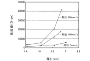
図5は厚さと電気抵抗値の関係を表したグラフであり、横軸は樹脂成形品又は試験片の厚さ、縦軸は電気抵抗値とした。
射出速度300mm/秒の場合は、厚さが1.6mm以下では、電気抵抗値が微小であり、厚さが1.6mmを超え、2mmに近づく程、電気抵抗値は急増した。
射出速度100mm/秒の場合も、厚さが1.6mm以下では、電気抵抗値が微小であり、厚さが1.6mmを超え、2mmに近づく程、電気抵抗値は急増した。
FIG. 5 is a graph showing the relationship between the thickness and the electric resistance value. The horizontal axis represents the thickness of the resin molded product or the test piece, and the vertical axis represents the electric resistance value.
When the injection speed was 300 mm / second, the electrical resistance value was very small when the thickness was 1.6 mm or less, and the electrical resistance value increased rapidly as the thickness exceeded 1.6 mm and approached 2 mm.
Even at an injection speed of 100 mm / sec, the electrical resistance value was very small when the thickness was 1.6 mm or less, and the electrical resistance value increased rapidly as the thickness exceeded 1.6 mm and approached 2 mm.
射出速度5mm/秒の場合は、厚さが1.8mm以下では、電気抵抗値が微小であり、厚さが2mmに近づく程、電気抵抗値は微増した。
以上のことから、同一射出材料であっても、射出速度を変えることで、表面における電気抵抗値を変化させることができる。また、中央の1.6mm厚さでは、電気抵抗値は微小であり、この値は射出速度に影響されないことが分かった。
以上の現象を図面で考察する。
When the injection speed was 5 mm / second, the electrical resistance value was very small when the thickness was 1.8 mm or less, and the electrical resistance value slightly increased as the thickness approached 2 mm.
From the above, even with the same injection material, the electrical resistance value on the surface can be changed by changing the injection speed. Further, it was found that the electrical resistance value is very small at the central thickness of 1.6 mm, and this value is not affected by the injection speed.
The above phenomenon will be considered in the drawings.
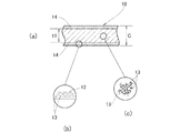
図6は樹脂成形品におけるカーボンナノ材料の分布模式図であり、樹脂成形品10の厚さ中心は電気抵抗値が小さいため、(c)に示すように線状のカーボンナノ材料13が縦横に配列されていると推定できる。
一方、表皮14が電気抵抗値を稼いでいることから、(b)に示すようにカーボンナノ材料13が横に配列されていると推定できる。横であれば、厚さ方向の電気抵抗値が大きくなるからである。
FIG. 6 is a schematic diagram of the distribution of the carbon nanomaterial in the resin molded product. Since the electrical resistance value is small at the thickness center of the resin molded
On the other hand, since the
表皮14、14は金型に接触して形成されるが、この際、溶融樹脂が金型に沿って流れ、この流れに沿ってカーボンナノ材料13が揃うと考えられ、且つ厚さ中央とは異なり表皮14の部位では、カーボンナノ材料13は姿勢が変わる前に急冷・凝固するために、(b)のようになると思われる。この傾向は射出速度が大きいほど顕著になると予想される。
The
そこで、本発明者らは、再度、射出速度に注目し、射出速度を変えて射出成形を行った。射出条件は次のとおりである。
・材料:ポリプロピレン80質量%+ナノカーボンファイバ20質量%
・樹脂成形品の大きさ:60mm×60mm
・樹脂成形品の厚さ:2mm
・射出速度:10mm/秒、100mm/秒又は300mm/秒
Therefore, the inventors paid attention to the injection speed again and changed the injection speed to perform injection molding. The injection conditions are as follows.
・ Material: 80% by mass of polypropylene + 20% by mass of nanocarbon fiber
-Resin molded product size: 60mm x 60mm
・ Thickness of resin molded product: 2mm
・ Injection speed: 10 mm / second, 100 mm / second or 300 mm / second
そして、インピーダンスアナライザで樹脂成形品の交流の電気抵抗値を測定し、その結果を次図に示す。
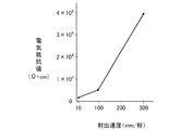
図7は樹脂成形品での射出速度と電気抵抗値の相関図であり、横軸は射出速度、縦軸は電気抵抗値を示す。
射出速度を300mm/秒にすると、電気抵抗値は4×104kΩ・cmまで増加した。すなわち、絶縁性が高まった。
And the electrical resistance value of the alternating current of the resin molded product was measured with the impedance analyzer, and the result is shown in the following figure.
FIG. 7 is a correlation diagram between the injection speed and the electric resistance value in the resin molded product, where the horizontal axis indicates the injection speed and the vertical axis indicates the electric resistance value.
When the injection speed was 300 mm / sec, the electrical resistance value increased to 4 × 10 4 kΩ · cm. That is, the insulating property was increased.
次に、熱伝導性を調べる。
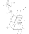
図8は本発明で採用した熱伝導性実験装置の原理図であり、実験装置20は、80℃に保つことのできるヒータブロック21と、このヒータブロック21に当てた樹脂成形品10の先端に当てる断熱材22と、この断熱材22を介して樹脂成形品10をヒータブロック21へ押圧する押さえ片23と、樹脂成形品10の表面に設けた3個の熱電対24、25、26と、検出した電圧を電流に変換する変換器27と、例えばアナログ温度記録計28とからなる。
Next, the thermal conductivity is examined.
FIG. 8 is a diagram showing the principle of the thermal conductivity experimental apparatus employed in the present invention. The
熱電対24はヒータブロック21から10mm,熱電対25は同30mm(樹脂成形品10の中央に相当),熱電対26はヒータブロック21から50mmのポジションに設けた。
そして、アナログ温度記録計28で温度曲線を監視し、温度上昇変化が微小となったときに、温度を記録する。
The
Then, the temperature curve is monitored by the analog temperature recorder 28, and the temperature is recorded when the temperature rise change becomes minute.
熱伝導性を調べるために用意した樹脂成形品の成形条件は次のとおりである。
・材料:ポリプロピレン95質量%+ナノカーボンファイバ5質量%
又は、ポリプロピレン90質量%+ナノカーボンファイバ10質量%
・樹脂成形品の大きさ:60mm×60mm
・樹脂成形品の厚さ:2mm
・射出速度:5mm/秒又は300mm/秒
記録した温度は次に掲げる表に示すとおりである。
The molding conditions of the resin molded product prepared for examining the thermal conductivity are as follows.
・ Material: 95% by mass of polypropylene + 5% by mass of nanocarbon fiber
Or 90% by mass of polypropylene + 10% by mass of nanocarbon fiber
-Resin molded product size: 60mm x 60mm
・ Thickness of resin molded product: 2mm
Injection speed: 5 mm / second or 300 mm / second The recorded temperature is as shown in the following table.
射出速度が共に300mm/秒である実験2と実験4とを比較すると、T11で実験4の方が5.6℃高く、T12で実験4の方が3.6℃高く、T13で実験4の方が1.7℃高かった。実験4の方がカーボンナノファイバの添加量が多いため、熱伝導率λが大きくなり、表面での温度が高くなることが確認できた。
射出速度が共に5mm/秒である実験1と実験3とついても同様であった。
Comparing
The same was true for Experiment 1 and
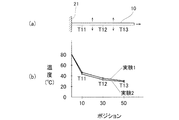
図9は本発明に係る実験1及び実験2の結果を示すグラフであり、(a)は樹脂成形品10のレイアウトを示し、ヒータブロック21で得た熱は、樹脂成形品10内を図左から右へ伝わる間に矢印で示すごとく表面から放散する。そのため、T11よりT12が低温となり、T12よりT13が低温になる。
FIG. 9 is a graph showing the results of Experiment 1 and
(b)は横軸が測温点のポジションを示し、縦軸は温度を示す。黒点(・)で実験1の結果をプロットした。そして、△で実験2の結果をプロットした。
熱伝導率λが無限大であれば、温度曲線はx軸に平行になる。また、熱伝導率λが無限小であれば、その逆になる。
実験1、実験2はx軸に略々平行であるから、カーボンナノファイバが5質量%で残りがポリプロピレンである樹脂成形品であっても、熱伝導性は良好である。
In (b), the horizontal axis indicates the position of the temperature measuring point, and the vertical axis indicates the temperature. The results of Experiment 1 were plotted with black dots (•). And the result of
If the thermal conductivity λ is infinite, the temperature curve is parallel to the x-axis. On the other hand, if the thermal conductivity λ is infinitesimal, the opposite is true.
Since Experiment 1 and
次に、重要な点は、(b)のグラフから実験1と実験2とに殆ど温度差がないことである。これは、図6で説明した表皮14、14は極く薄く、熱伝導に係る伝熱面積に殆ど影響しないことを意味する。
以上をまとめると、射出速度は熱伝導性には殆ど影響しない。一方、射出速度を高めると絶縁性の高い表皮14、14を樹脂成形品10に形成することができる。
この結果、本発明は、樹脂成形品において、カーボン材料を混入することで熱伝導率を高めるとともに、絶縁性を維持することができる技術を提供するものである。
Next, the important point is that there is almost no temperature difference between Experiment 1 and
In summary, injection speed has little effect on thermal conductivity. On the other hand, when the injection speed is increased, the highly
As a result, the present invention provides a technique capable of increasing the thermal conductivity and maintaining the insulation by mixing a carbon material in a resin molded product.
具体的には、請求項1に係る発明は、樹脂にカーボンナノ材料を添加し、射出成形することで得た樹脂成形品において、この樹脂成形品は、表皮と内部に区分したときに、カーボンナノ材料の向きが、内部では不揃いであり、表皮は表面にほぼ平行であることを特徴とする。 Specifically, the invention according to claim 1 is a resin molded product obtained by adding a carbon nanomaterial to a resin and performing injection molding. When the resin molded product is divided into a skin and an interior, carbon The orientation of the nanomaterial is uneven inside, and the epidermis is characterized by being almost parallel to the surface.
請求項2に係る発明は、樹脂にカーボンナノ材料を添加し、射出成形する樹脂成形品の製造方法において、電気抵抗値を下げる場合には低い射出速度で射出成形し、高い熱伝導性を維持しつつ表皮の電気抵抗値を上げる場合には高い射出速度で射出成形するごとくに、射出速度を制御要素にしたことを特徴とする。
The invention according to
請求項3に係る発明では、低い射出速度は5〜10mm/秒であることを特徴とする。
The invention according to
請求項4に係る発明では、高い射出速度は少なくとも300mm/秒であることを特徴とする。 The invention according to claim 4 is characterized in that the high injection speed is at least 300 mm / second.
請求項1に係る発明では、樹脂成形品は、カーボンナノ材料の向きが、内部では不揃いであり、表皮は表面にほぼ平行であることを特徴とする。
電気抵抗値を下げる役割を果たすカーボンナノ材料が、表面にほぼ平行に揃っていれば、表面に直交する方向、すなわち厚さ方向の電気抵抗値が上がる。したがって、表皮は厚さ方向の電気抵抗値を上げる役割を果たし、結果として絶縁性を確保することができる。しかし、表皮にカーボンナノ材料が存在するため低い導電性はある。このため、静電気が表皮に溜まることはなく、帯電を防止することができる。
In the invention according to claim 1, the resin molded product is characterized in that the orientation of the carbon nanomaterial is uneven inside, and the skin is substantially parallel to the surface.
If the carbon nanomaterials that play a role of lowering the electric resistance value are arranged substantially parallel to the surface, the electric resistance value in the direction perpendicular to the surface, that is, in the thickness direction is increased. Therefore, the skin plays a role of increasing the electrical resistance value in the thickness direction, and as a result, insulation can be ensured. However, since carbon nanomaterial exists in the skin, it has low conductivity. For this reason, static electricity does not accumulate in the epidermis and charging can be prevented.
また、熱伝導は内部の不揃いなカーボンナノ材料が有効に機能する。したがって、熱伝導性は十分に確保することができる。
したがって、請求項1によれば、熱伝導率を高めるとともに、絶縁性を維持することができる樹脂成形品を提供することができる。
In addition, carbon nanomaterials with irregular inside function effectively for heat conduction. Therefore, sufficient thermal conductivity can be ensured.
Therefore, according to the first aspect, it is possible to provide a resin molded product capable of increasing the thermal conductivity and maintaining the insulation.
請求項2に係る発明では、電気抵抗値を下げる場合には低い射出速度で射出成形し、高い熱伝導性を維持しつつ表皮の電気抵抗値を上げる場合には高い射出速度で射出成形するごとくに、射出速度を制御要素に射出成形品の特性を自在に変えることができる。
高価なカーボンナノ材料の添加量を抑え、低速で射出成形することで、良導電性成形品を得ることができ、コストの低減が可能となる。
また、高速で射出成形することで、熱伝導率を高めるとともに、絶縁性を維持することができる樹脂成形品を製造することができる。
In the invention according to
By suppressing the amount of expensive carbon nanomaterial added and injection molding at a low speed, a highly conductive molded product can be obtained, and the cost can be reduced.
Moreover, by performing injection molding at a high speed, it is possible to manufacture a resin molded product that can increase the thermal conductivity and maintain the insulation.
請求項3に係る発明では、低い射出速度は5〜10mm/秒とした。5mm/秒未満では成形品に品質のむらが発生する可能性が高まると共に生産性が低下する。
また、10mm/秒を超えると表皮中のカーボンナノ材料が不揃いになる。そのため、射出速度は5〜10mm/秒とすることが望ましい。
In the invention which concerns on
Moreover, when it exceeds 10 mm / sec, the carbon nanomaterials in the epidermis become uneven. Therefore, the injection speed is desirably 5 to 10 mm / second.
請求項4に係る発明では、高い射出速度は少なくとも300mm/秒とした。ポリプロピレン80質量%+ナノカーボンファイバ20質量%の混合材料を、300mm/秒の射出速度で樹脂成形したところ、射出成形品の電気抵抗値は4×104kΩ・cmであった。
300mm/秒未満の射出速度では、電気抵抗値は4×104kΩ・cm未満となる。必要な絶縁性が得られないため、高い射出速度は少なくとも300mm/秒とすることが望まれる。
In the invention according to claim 4, the high injection speed is at least 300 mm / second. When a mixed material of 80% by mass of polypropylene + 20% by mass of nanocarbon fiber was resin-molded at an injection speed of 300 mm / sec, the electric resistance value of the injection-molded product was 4 × 10 4 kΩ · cm.
At an injection speed of less than 300 mm / sec, the electrical resistance value is less than 4 × 10 4 kΩ · cm. Since the necessary insulation cannot be obtained, it is desirable that the high injection speed is at least 300 mm / second.
本発明を実施するための最良の形態を添付図に基づいて以下に説明する。
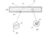
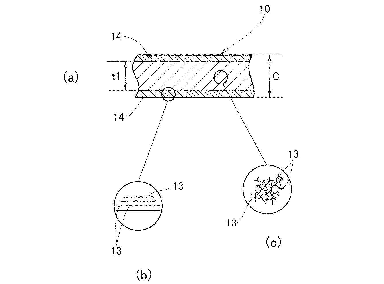
図10は本発明に係る樹脂成形品の断面図であり、(a)に示す樹脂成形品10は、表皮14と内部15に区分したときに、カーボンナノ材料13の向きが、内部15では不揃いであり、表皮14は表面にほぼ平行であることを特徴とする。
すなわち、(c)に示すように内部15には、線状のカーボンナノ材料13が縦横に配列されており、(b)に示すように表皮14にはカーボンナノ材料13が表面に平行に配列されている。
The best mode for carrying out the present invention will be described below with reference to the accompanying drawings.
FIG. 10 is a cross-sectional view of the resin molded product according to the present invention. When the resin molded
That is, as shown in (c),
なお、上述のカーボンナノ材料13は、厳密に縦横や平行に配列したと解釈する必要はなく、カーボンナノ材料を含む樹脂成形品が、厚さ方向に電気抵抗値が高く、全体として熱伝導性が高ければ、厳密な姿勢は問わないものとする。
The above-mentioned
樹脂成形品10の様に、電気抵抗値を下げる役割を果たすカーボンナノ材料が、表面にほぼ平行に揃っていれば、表面に直交する方向、すなわち厚さ方向の電気抵抗値が上がる。したがって、表皮は厚さ方向の電気抵抗値を上げる役割を果たし、結果として絶縁性を確保することができる。しかし、表皮にカーボンナノ材料が存在するため低い導電性はある。このため、静電気が表皮に溜まることはなく、帯電を防止することができる。
If the carbon nanomaterial that plays the role of lowering the electrical resistance value as in the resin molded
また、熱伝導は内部の不揃いなカーボンナノ材料が有効に機能する。したがって、熱伝導性は十分に確保することができる。 In addition, carbon nanomaterials with irregular inside function effectively for heat conduction. Therefore, sufficient thermal conductivity can be ensured.
なお、カーボンナノ材料は、カーボンナノファイバ、カーボンナノチューブ、カーボンナノフラーレンの何れであってもよく、材質が炭素で、ナノレベルのサイズを含む物であれば形態は任意である。 The carbon nanomaterial may be any of carbon nanofibers, carbon nanotubes, and carbon nanofullerenes, and the form is arbitrary as long as the material is carbon and includes a nano-level size.
本発明は、カーボン材料を混入することで熱伝導率を高めた樹脂成形品に好適である。 The present invention is suitable for a resin molded product in which thermal conductivity is increased by mixing a carbon material.
10…樹脂成形品、12…試験片、13…カーボンナノ材料、14…表皮、15…内部、110…カーボンナノファイバ。
DESCRIPTION OF
Claims (4)
この樹脂成形品は、表皮と内部に区分したときに、カーボンナノ材料の向きが、内部では不揃いであり、表皮は表面にほぼ平行であることを特徴とする樹脂成形品。 In resin molded products obtained by adding carbon nanomaterial to resin and injection molding,
When the resin molded product is divided into the skin and the inside, the orientation of the carbon nanomaterial is uneven inside, and the skin is substantially parallel to the surface.
The method for producing a resin molded product according to claim 2, wherein the high injection speed is at least 300 mm / second.
Priority Applications (1)
| Application Number | Priority Date | Filing Date | Title |
|---|---|---|---|
| JP2004112134A JP4080450B2 (en) | 2004-04-06 | 2004-04-06 | Manufacturing method of resin molded products |
Applications Claiming Priority (1)
| Application Number | Priority Date | Filing Date | Title |
|---|---|---|---|
| JP2004112134A JP4080450B2 (en) | 2004-04-06 | 2004-04-06 | Manufacturing method of resin molded products |
Publications (2)
| Publication Number | Publication Date |
|---|---|
| JP2005297210A true JP2005297210A (en) | 2005-10-27 |
| JP4080450B2 JP4080450B2 (en) | 2008-04-23 |
Family
ID=35329359
Family Applications (1)
| Application Number | Title | Priority Date | Filing Date |
|---|---|---|---|
| JP2004112134A Expired - Fee Related JP4080450B2 (en) | 2004-04-06 | 2004-04-06 | Manufacturing method of resin molded products |
Country Status (1)
| Country | Link |
|---|---|
| JP (1) | JP4080450B2 (en) |
Cited By (2)
| Publication number | Priority date | Publication date | Assignee | Title |
|---|---|---|---|---|
| JP2007168263A (en) * | 2005-12-22 | 2007-07-05 | Seiko Precision Inc | Resin casing for electronic equipment and method of manufacturing resin molded product |
| WO2012039397A1 (en) * | 2010-09-24 | 2012-03-29 | シャープ株式会社 | Light-emitting device, lighting device, and display device |
-
2004
- 2004-04-06 JP JP2004112134A patent/JP4080450B2/en not_active Expired - Fee Related
Cited By (2)
| Publication number | Priority date | Publication date | Assignee | Title |
|---|---|---|---|---|
| JP2007168263A (en) * | 2005-12-22 | 2007-07-05 | Seiko Precision Inc | Resin casing for electronic equipment and method of manufacturing resin molded product |
| WO2012039397A1 (en) * | 2010-09-24 | 2012-03-29 | シャープ株式会社 | Light-emitting device, lighting device, and display device |
Also Published As
| Publication number | Publication date |
|---|---|
| JP4080450B2 (en) | 2008-04-23 |
Similar Documents
| Publication | Publication Date | Title |
|---|---|---|
| Liu et al. | Thermal conductivity improvement of silicone elastomer with carbon nanotube loading | |
| Wang et al. | Flexible TPU/MWCNTs/BN composites for frequency-selective electromagnetic shielding and enhanced thermal conductivity | |
| JP5205947B2 (en) | Resin carbon composite material | |
| Matzeu et al. | A temperature sensor based on a MWCNT/SEBS nanocomposite | |
| JP4697829B2 (en) | Carbon nanotube composite molded body and method for producing the same | |
| Khan et al. | Development of additively manufacturable and electrically conductive graphite–polymer composites | |
| Dul et al. | Fused filament fabrication of piezoresistive carbon nanotubes nanocomposites for strain monitoring | |
| JP5541399B2 (en) | Thermally conductive sheet | |
| US10773955B2 (en) | Composite material containing graphene | |
| Castellino et al. | Electrical conductivity phenomena in an epoxy resin–carbon-based materials composite | |
| KR101144888B1 (en) | Flexible thermoelectric material, method for preparing the same and thermoelectric device comprising the same | |
| JPWO2013099089A1 (en) | Molded product of sheet anisotropic heat conductive composition | |
| Zhang et al. | Polyurethane/carbon fiber composite tubular electrode featuring three-dimensional interpenetrating conductive network | |
| Lin et al. | Effect of carbon black structure on the effectiveness of carbon black thermal interface pastes | |
| Putson et al. | Effects of copper filler sizes on the dielectric properties and the energy harvesting capability of nonpercolated polyurethane composites | |
| Pak et al. | Micro-Macroscopic coupled modeling for the prediction of synergistic improvement on the thermal conductivity of boron nitride and multi-walled carbon nanotube reinforced composites | |
| Costi et al. | 3D Printable Self‐Sensing Magnetorheological Elastomer | |
| JP4080450B2 (en) | Manufacturing method of resin molded products | |
| KR101467353B1 (en) | Sheet-type hybrid heating composite | |
| JP6153702B2 (en) | Variable thermal conductivity material | |
| Rizvi et al. | Effect of carbon nanoparticle type, content, and stress on piezoresistive polyethylene nanocomposites | |
| Nejad | A review on modeling of the thermal conductivity of polymeric nanocomposites | |
| Njuguna | Characterisation of multi wall carbon nanotube–polymer composites for strain sensing applications | |
| Gao et al. | Flexible self-assembly carbon nanotube/polyimide thermal film endowed adjustable temperature coefficient of resistance | |
| Hostler et al. | Thermal and electrical characterization of nanocomposites for thermoelectrics |
Legal Events
| Date | Code | Title | Description |
|---|---|---|---|
| A621 | Written request for application examination |
Free format text: JAPANESE INTERMEDIATE CODE: A621 Effective date: 20050914 |
|
| A977 | Report on retrieval |
Free format text: JAPANESE INTERMEDIATE CODE: A971007 Effective date: 20070727 |
|
| A131 | Notification of reasons for refusal |
Free format text: JAPANESE INTERMEDIATE CODE: A131 Effective date: 20070807 |
|
| A521 | Written amendment |
Free format text: JAPANESE INTERMEDIATE CODE: A523 Effective date: 20071009 |
|
| A131 | Notification of reasons for refusal |
Free format text: JAPANESE INTERMEDIATE CODE: A131 Effective date: 20071121 |
|
| A521 | Written amendment |
Free format text: JAPANESE INTERMEDIATE CODE: A523 Effective date: 20080107 |
|
| TRDD | Decision of grant or rejection written | ||
| A01 | Written decision to grant a patent or to grant a registration (utility model) |
Free format text: JAPANESE INTERMEDIATE CODE: A01 Effective date: 20080205 |
|
| A61 | First payment of annual fees (during grant procedure) |
Free format text: JAPANESE INTERMEDIATE CODE: A61 Effective date: 20080206 |
|
| FPAY | Renewal fee payment (event date is renewal date of database) |
Free format text: PAYMENT UNTIL: 20110215 Year of fee payment: 3 |
|
| R150 | Certificate of patent or registration of utility model |
Free format text: JAPANESE INTERMEDIATE CODE: R150 |
|
| FPAY | Renewal fee payment (event date is renewal date of database) |
Free format text: PAYMENT UNTIL: 20110215 Year of fee payment: 3 |
|
| FPAY | Renewal fee payment (event date is renewal date of database) |
Free format text: PAYMENT UNTIL: 20120215 Year of fee payment: 4 |
|
| FPAY | Renewal fee payment (event date is renewal date of database) |
Free format text: PAYMENT UNTIL: 20140215 Year of fee payment: 6 |
|
| R250 | Receipt of annual fees |
Free format text: JAPANESE INTERMEDIATE CODE: R250 |
|
| LAPS | Cancellation because of no payment of annual fees |