JP2005297085A - Machine Tools - Google Patents

Machine Tools Download PDF

Info

Publication number
JP2005297085A
JP2005297085A JP2004112683A JP2004112683A JP2005297085A JP 2005297085 A JP2005297085 A JP 2005297085A JP 2004112683 A JP2004112683 A JP 2004112683A JP 2004112683 A JP2004112683 A JP 2004112683A JP 2005297085 A JP2005297085 A JP 2005297085A
Authority
JP
Japan
Prior art keywords
machining
axis
workpiece
machine tool
movable
Prior art date
Legal status (The legal status is an assumption and is not a legal conclusion. Google has not performed a legal analysis and makes no representation as to the accuracy of the status listed.)
Withdrawn
Application number
JP2004112683A
Other languages
Japanese (ja)
Inventor
Hikari Ishigaki
光 石垣
Ryuichi Fujiwara
竜一 藤原
Toshiaki Odaka
利明 小高
Current Assignee (The listed assignees may be inaccurate. Google has not performed a legal analysis and makes no representation or warranty as to the accuracy of the list.)
DMG Mori Co Ltd
Original Assignee
Mori Seiki Co Ltd
Priority date (The priority date is an assumption and is not a legal conclusion. Google has not performed a legal analysis and makes no representation as to the accuracy of the date listed.)
Filing date
Publication date
Application filed by Mori Seiki Co Ltd filed Critical Mori Seiki Co Ltd
Priority to JP2004112683A priority Critical patent/JP2005297085A/en
Publication of JP2005297085A publication Critical patent/JP2005297085A/en
Withdrawn legal-status Critical Current

Links

Images

Landscapes

  • Auxiliary Devices For Machine Tools (AREA)

Abstract

【課題】長尺ワークを加工する場合にもカバーを小型化でき、コストの上昇を抑制できる工作機械を提供する。
【解決手段】コラム8を左,右のコラム本体15,16の前,後端部同士を前,後のクロスフレーム17,18で結合してなるものとし、該前,後のクロスフレーム17,18と上記左,右のコラム本体15,16と加工テーブル5とで形成された前,後の開口8a,8bに切り屑やクーラントが機外に飛散するのを防止する遮蔽機構50を配設する。
【選択図】 図5
A machine tool capable of reducing the size of a cover even when processing a long workpiece and suppressing an increase in cost.
A column 8 is formed by connecting front and rear ends of left and right column main bodies 15 and 16 with front and rear cross frames 17 and 18, respectively. 18 and the left and right column main bodies 15 and 16 and the processing table 5 are provided with a shielding mechanism 50 for preventing chips and coolant from being scattered outside the machine in the front and rear openings 8a and 8b. To do.
[Selection] Figure 5

Description

本発明は、工具が装着された主軸をX軸,Y軸,Z軸方向に相対移動させることにより加工テーブルに搭載されたワークに所定の加工を施すようにした工作機械に関する。   The present invention relates to a machine tool that performs predetermined machining on a workpiece mounted on a machining table by relatively moving a spindle on which a tool is mounted in the X-axis, Y-axis, and Z-axis directions.

比較的長尺のワークを加工するためのガントリ形マシニングセンタとして、例えば、特許文献1又は2に記載されたものがある。特許文献1のものは、長尺状のベッド2に門形のコラム7をX軸方向に移動可能に配設し、該コラム7のクロスレール7cの前面にサドル25をY軸方向に移動可能に配設し、該サドル25にラム30をZ軸方向に移動可能に配設し、該ラム30に、工具32が装着された主軸31を配設した構造となっている。   As a gantry type machining center for processing a relatively long workpiece, for example, there is one described in Patent Document 1 or 2. In Patent Document 1, a gate-shaped column 7 is arranged on a long bed 2 so as to be movable in the X-axis direction, and a saddle 25 can be moved in the Y-axis direction on the front surface of the cross rail 7c of the column 7. The ram 30 is disposed on the saddle 25 so as to be movable in the Z-axis direction, and a main shaft 31 on which a tool 32 is mounted is disposed on the ram 30.

この種のマシニングセンタでは、ベッド2上に比較的長尺のワークWを搭載し、コラム7,サドル25,ラム30をそれぞれX軸,Y軸,Z軸方向に相対移動させて主軸31により上記ワークWに所定の加工を行うようになっている。
特開2001−219325号公報 特開平8−150534号公報
In this type of machining center, a relatively long workpiece W is mounted on the bed 2, and the column 7, the saddle 25, and the ram 30 are relatively moved in the X-axis, Y-axis, and Z-axis directions, respectively, and the above-described workpiece is moved by the main shaft 31. A predetermined processing is performed on W.
JP 2001-219325 A JP-A-8-150534

ところで上記マシニングセンタでは、加工中の切り屑やクーラントが機外に飛散するのを防止するために機械本体の外周部をカバーで囲んで遮蔽するのが一般的である。   By the way, in the above machining center, in order to prevent chips and coolant being processed from being scattered outside the machine, it is general that the outer periphery of the machine body is surrounded by a cover and shielded.

ところが、上記従来装置のように比較的大きな長尺ワークを加工する工作機械の機械本体外周部をカバーで遮蔽する構造を採用した場合には、遮蔽面積が大きくなり、カバーが大型化し、コストが上昇するという問題がある。   However, in the case of adopting a structure that shields the outer periphery of the machine body of a machine tool that processes relatively large long workpieces with a cover as in the conventional device, the shielding area increases, the cover becomes larger, and the cost is reduced. There is a problem of rising.

本発明は、上記従来の実情に鑑みてなされたもので、長尺ワークを加工する場合にもカバーのコスト上昇を抑制できる工作機械を提供することを目的としている。   The present invention has been made in view of the above-described conventional situation, and an object thereof is to provide a machine tool capable of suppressing an increase in the cost of a cover even when a long workpiece is machined.

請求項1の発明は、工具が装着された主軸を相対移動させることにより加工テーブルに搭載されたワークに所定の加工を施すようにした工作機械において、上記主軸を加工ユニットにより上記加工テーブルに対してX軸,Y軸,Z軸方向に相対移動可能に支持し、該加工ユニットに切り屑やクーラントが加工エリア外に飛散するのを防止する遮蔽機構を設けたことを特徴としている。   According to the first aspect of the present invention, in a machine tool configured to perform a predetermined process on a workpiece mounted on a machining table by relatively moving a spindle on which a tool is mounted, the spindle is moved with respect to the machining table by a machining unit. The shielding unit is provided with a shielding mechanism that supports relative movement in the X-axis, Y-axis, and Z-axis directions and prevents the chips and coolant from scattering outside the machining area.

請求項2の発明は、請求項1において、上記加工ユニットは、上記加工テーブルの左,右に立設された左,右のコラム本体の前,後端部同士を前,後のクロスフレームで結合してなるコラムを備え、上記主軸は、該前,後のクロスフレームと上記左,右のコラム本体とで囲まれた部分に軸線を略鉛直に向けて配置されており、上記遮蔽機構は、上記前,後のクロスフレームに上下動可能に吊設され、上記コラム本体,クロスフレーム及び加工テーブルで形成された前,後の開口を開閉する前,後の遮蔽部材を備えていることを特徴としている。   According to a second aspect of the present invention, in the first aspect, the processing unit includes a front and rear cross frame at the front and rear ends of the left and right column bodies erected on the left and right of the processing table. The main shaft is disposed in a portion surrounded by the front and rear cross frames and the left and right column main bodies with the axis line oriented substantially vertically, and the shielding mechanism is The front and rear cross frames are suspended in a vertically movable manner, and include front and rear shielding members that open and close the front and rear openings formed by the column body, the cross frame and the processing table. It is a feature.

請求項3の発明は、請求項2において、上記加工テーブルは一方向に配置された複数の加工エリアを有し、上記加工ユニットは、上記加工エリアの配置方向に延びる長尺状のベッド上に該加工エリア配置方向に移動可能に搭載され、何れかの加工エリアに位置決めされた状態で上記主軸をX軸,Y軸及びZ軸方向に移動させることにより上記ワークの加工を行うように構成されており、上記前,後の遮蔽部材は、上記加工ユニットを何れかの加工エリアに位置決めした状態で上記前,後の開口を開閉するように構成されていることを特徴としている。   According to a third aspect of the present invention, in the second aspect, the processing table has a plurality of processing areas arranged in one direction, and the processing unit is on a long bed extending in the arrangement direction of the processing areas. The workpiece is mounted so as to be movable in the machining area arrangement direction, and the workpiece is machined by moving the spindle in the X-axis, Y-axis, and Z-axis directions while being positioned in any machining area. The front and rear shielding members are configured to open and close the front and rear openings in a state where the processing unit is positioned in any processing area.

請求項4の発明は、請求項2又は3において、上記遮蔽部材は、上記左,右のコラム本体間に渡るように配設された前,後の棒材に多数の帯板状カーテンプレートを懸吊支持し、該棒材を駆動機構により上記開口を略閉塞する閉位置と開放する開位置との間で昇降駆動するように構成されていることを特徴としている。   According to a fourth aspect of the present invention, in the second or third aspect, the stripping member is provided with a large number of strip-like car templates on the front and rear bars disposed so as to extend between the left and right column bodies. It is characterized in that it is suspended and supported, and the bar is driven up and down between a closed position where the opening is substantially closed and an open position where the bar is opened by a drive mechanism.

請求項5の発明は、請求項4において、上記各カーテンプレートは、上記棒材に上下移動可能に吊り下げられており、上記棒材を閉位置に下降させるとワークに当接した位置に停まることを特徴としている。   According to a fifth aspect of the present invention, the car template according to the fourth aspect is suspended from the bar so as to be movable up and down. When the bar is lowered to the closed position, the car template stops at a position in contact with the workpiece. It is characterized by being.

請求項6の発明は、請求項4又は5において、上記各カーテンプレートは、上記棒材に支持された上側プレートと該上側プレートに上下方向に移動可能に支持された下側プレートとから構成されており、上記棒材を閉位置に下降させると下側プレートはワークに当接した位置に停まることを特徴としている。   The invention of claim 6 is the invention according to claim 4 or 5, wherein each car template is composed of an upper plate supported by the bar and a lower plate supported by the upper plate so as to be movable in the vertical direction. When the bar is lowered to the closed position, the lower plate stops at a position in contact with the workpiece.

請求項1の発明に係る工作機械によれば、主軸を移動可能に支持する加工ユニットに遮蔽機構を設けたので、従来の機械本体の外周全体を遮蔽する場合に比べて遮蔽機構を小型化でき、ひいてはコストの上昇を抑制できる。   According to the machine tool of the first aspect of the present invention, since the shielding mechanism is provided in the processing unit that movably supports the main shaft, the shielding mechanism can be reduced in size compared to the conventional case where the entire outer periphery of the machine body is shielded. As a result, an increase in cost can be suppressed.

請求項2の発明によれば、コラムを左,右のコラム本体の前,後端部同士を前,後のクロスフレームで結合してなるものとし、上記遮蔽機構を左,右のコラム本体,クロスフレーム及び加工テーブルで形成された前,後の開口を開閉する前,後の遮蔽部材で構成したので、主軸の加工領域の左,右側方はコラム本体により遮蔽でき、左,右のコラム本体と前,後のクロスフレームにより形成された前,後の開口だけを遮蔽すればよく、従来の機械本体の外周全体を遮蔽する場合に比べて遮蔽部材を小型化でき、コスト上昇を抑制できる。   According to the invention of claim 2, the column is formed by connecting the front and rear ends of the left and right column main bodies with the front and rear cross frames, and the shielding mechanism includes the left and right column main bodies, Since the front and rear openings formed by the cross frame and the processing table are composed of the front and rear shielding members, the left and right sides of the spindle machining area can be shielded by the column body, and the left and right column bodies In addition, only the front and rear openings formed by the front and rear cross frames need to be shielded, and the shielding member can be reduced in size compared to the conventional case where the entire outer periphery of the machine body is shielded, thereby suppressing an increase in cost.

請求項3の発明では、加工ユニットを何れかの加工エリアに移動させて位置決めした状態で、遮蔽部材により前,後の開口を開閉するようにしたので、加工テーブルに搭載された長尺ワークの加工を行う際のワーク上方の開口を遮蔽することができる。   In the invention of claim 3, since the front and rear openings are opened and closed by the shielding member in a state where the processing unit is moved to any processing area and positioned, the long workpiece mounted on the processing table The opening above the workpiece when machining can be shielded.

請求項4の発明では、棒材に懸吊支持された多数の帯板状カーテンプレートを閉位置と開位置との間で昇降駆動したので、遮蔽部材を簡単な構造でかつ特別な設置スペースを設けることなく配置できるとともに、加工ユニットを次の加工エリアに移動させる際には、カーテンプレートを上昇させておくことによりカーテンプレートがワークに干渉するのを防止できる。   In the invention of claim 4, since a number of strip-plate car templates suspended and supported by the bar are driven up and down between the closed position and the open position, the shielding member has a simple structure and a special installation space. It can be arranged without providing, and when the machining unit is moved to the next machining area, it is possible to prevent the car template from interfering with the workpiece by raising the car template.

請求項5の発明では、カーテンプレートが下降してワークに当接するとその位置に停まるように構成したので、高さ位置の異なる形状を有する長尺ワークの加工を行う際のワーク上方の開口を自動的にかつ確実に遮蔽することができる。   In the fifth aspect of the invention, since the car template is configured to stop when the car template descends and comes into contact with the workpiece, the opening above the workpiece when machining a long workpiece having a shape with a different height position is provided. Can be automatically and reliably shielded.

請求項6の発明では、上記カーテンプレートを棒材に支持された上側プレートと該上側プレートに上下移動可能に支持された下側プレートとから構成したので、簡単な構造で高さ位置の異なる形状を有する長尺ワークの上方開口を下側プレートが上方に相対移動することによって、自動的にかつ確実に遮蔽することができる。   In the invention of claim 6, since the car template is composed of the upper plate supported by the bar and the lower plate supported by the upper plate so as to be movable up and down, the shape is different in height position with a simple structure. When the lower plate relatively moves upward, the upper opening of the long workpiece having the above can be automatically and reliably shielded.

以下、本発明の実施の形態を添付図面に基づいて説明する。   Hereinafter, embodiments of the present invention will be described with reference to the accompanying drawings.

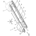
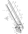
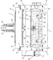
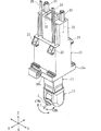
図1ないし図6は、本発明の一実施形態(第1実施形態)によるガントリ形マシニングセンタ(工作機械)を説明するための図であり、図1,図2はガントリ形マシニングセンタの全体斜視図、図3はガントリ形マシニングセンタの加工ユニットの斜視図、図4,図5は遮蔽機構が配設された加工ユニットの断面側面図,正面図、図6は加工ユニットの主軸部分の斜視図である。   1 to 6 are views for explaining a gantry type machining center (machine tool) according to one embodiment (first embodiment) of the present invention. FIGS. 1 and 2 are perspective views of the entire gantry type machining center. 3 is a perspective view of a machining unit of the gantry type machining center, FIGS. 4 and 5 are sectional side views and front views of the machining unit provided with a shielding mechanism, and FIG. 6 is a perspective view of a main shaft portion of the machining unit.

図において、1はガントリ形マシニングセンタを示しており、これは工具Tが装着された主軸2をX軸,Y軸,Z軸の3軸方向に相対移動可能に支持する加工ユニット3と、該加工ユニット3を上記X軸方向と平行なU軸方向に移動可能に支持する左,右一対のベッド4,4とから構成されている。   In the figure, reference numeral 1 denotes a gantry machining center, which includes a machining unit 3 that supports a spindle 2 on which a tool T is mounted so as to be relatively movable in three axial directions of an X axis, a Y axis, and a Z axis. The unit 3 includes a pair of left and right beds 4 and 4 that support the unit 3 so as to be movable in the U-axis direction parallel to the X-axis direction.

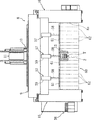
上記左,右のベッド4,4の間には加工テーブル5が配置されている。この加工テーブル5は、長さが20〜30mで幅が3〜5mに渡る大きさのものであり、上記U軸方向に配置された複数の加工エリアa1〜a4を有している。また上記左,右のベッド4,4のU軸方向両端部には加工テーブル5のU軸方向外側に位置するよう加工ユニット3の退避スペースが設けられており、該退避スペースに加工ユニット3を位置させた状態で幅広長尺ワークWを上下方向に着脱できるようになっている。   A processing table 5 is disposed between the left and right beds 4 and 4. The machining table 5 has a length ranging from 20 to 30 m and a width ranging from 3 to 5 m, and has a plurality of machining areas a1 to a4 arranged in the U-axis direction. Further, a retreat space for the processing unit 3 is provided at both ends of the left and right beds 4 and 4 in the U-axis direction so as to be located on the outer side of the processing table 5 in the U-axis direction. The wide and long workpiece W can be attached and detached in the up and down direction while being positioned.

上記加工ユニット3は、機械正面から上記U軸方向に見たとき、加工テーブル5を跨ぐように左,右のベッド4,4に搭載された門形コラム8と、該コラム8によりX軸方向に移動可能に支持されたクロスレール9と、該クロスレール9によりY軸方向に移動可能に支持されたサドル10と、該サドル10によりZ軸方向に移動可能に支持されたラム11とを備えており、該ラム11の下端に上記主軸2が軸線を概ね垂直方向に向けて配設されている。   The machining unit 3 includes a portal column 8 mounted on the left and right beds 4 and 4 so as to straddle the machining table 5 when viewed from the front of the machine in the U-axis direction, and the column 8 allows the X-axis direction. A cross rail 9 supported so as to be movable, a saddle 10 supported so as to be movable in the Y-axis direction by the cross rail 9, and a ram 11 supported so as to be movable in the Z-axis direction by the saddle 10. The main shaft 2 is disposed at the lower end of the ram 11 with its axis line oriented substantially vertically.

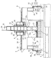
上記ラム11は、図6に示すように、主軸2を軸直角回りのA軸方向に回転割り出し駆動するとともに、主軸2を軸線回りのC軸方向に回転割り出し駆動する回転割り出し装置13を備えており、これにより5軸制御によるワーク加工が行えるようになっている。   As shown in FIG. 6, the ram 11 includes a rotary indexing device 13 for rotationally indexing and driving the main shaft 2 in the A-axis direction around the axis and rotating and driving the main shaft 2 in the C-axis direction around the axis. Thus, the workpiece can be machined by 5-axis control.

上記門形コラム8は、左,右のベッド4上に配置された前後方向に延びる側面視略長方形状の左,右のコラム本体15,16の前壁,後壁同士を前,後のクロスフレーム17,18により一体的に結合した構造となっている。上記前,後のクロスフレーム17,18と左,右のコラム本体15,16とで囲まれた部分に上記主軸2が配置されている。上記左,右のコラム本体15,16は各ベッド4,4の上面に配設された一対のU軸ガイドレール19,19により上記U軸方向に移動可能に支持されている。   The portal column 8 is arranged on the left and right beds 4 and has a substantially rectangular shape in a side view extending in the front-rear direction. The front and rear walls of the left and right column bodies 15 and 16 are front and rear crosses. The frame 17 and 18 are integrally connected. The main shaft 2 is disposed in a portion surrounded by the front and rear cross frames 17 and 18 and the left and right column bodies 15 and 16. The left and right column bodies 15 and 16 are supported by a pair of U-axis guide rails 19 and 19 disposed on the upper surfaces of the beds 4 and 4 so as to be movable in the U-axis direction.

上記クロスレール9は、上下方向に開口した矩形箱状のものからなり、平面視で、上記左,右のコラム本体15,16及び前,後のクロスフレーム17,18とで囲まれた空間内に配置されている。またクロスレール9の左右上縁部にはフランジ部9a,9aが形成されており、該左,右のフランジ部9aが各コラム本体15,16の上面に配設されたX軸ガイドレール21,21によりX軸方向に移動可能に支持されている。   The cross rail 9 has a rectangular box shape opened in the vertical direction, and in a space surrounded by the left and right column main bodies 15 and 16 and the front and rear cross frames 17 and 18 in plan view. Is arranged. Further, flange portions 9a, 9a are formed on the left and right upper edge portions of the cross rail 9, and the left and right flange portions 9a are arranged on the upper surfaces of the column main bodies 15, 16, respectively. 21 is supported so as to be movable in the X-axis direction.

上記サドル10は、上下方向に開口する角筒状のものからなり、上記クロスレール9内に配置されている。このサドル10の前,後壁にはそれぞれ一対の三角ブラケット25,25が取付け固定されており、この前,後の各ブラケット25,25がクロスレール9の前,後上面に配設されたY軸ガイドレール26,26によりY軸方向に移動可能に支持されている。   The saddle 10 is a rectangular tube that opens in the vertical direction, and is disposed in the cross rail 9. A pair of triangular brackets 25 and 25 are attached and fixed to the front and rear walls of the saddle 10, respectively. The front and rear brackets 25 and 25 are disposed on the front and rear upper surfaces of the cross rail 9, respectively. The shaft guide rails 26 and 26 are supported so as to be movable in the Y-axis direction.

また上記サドル10の前,後壁の下縁にはフランジ部10a,10aが形成されており、該前,後のフランジ部10aがクロスレール9の前,後下面に配設されたY軸ガイドレール27,27によりY軸方向に移動可能に支持されている。このようにしてサドル10は上,下のY軸ガイドレール26,27により挟持されている。   Further, flange portions 10a and 10a are formed on the lower edges of the front and rear walls of the saddle 10, and the front and rear flange portions 10a are disposed on the front and rear lower surfaces of the cross rail 9, respectively. The rails 27 and 27 are supported so as to be movable in the Y-axis direction. In this way, the saddle 10 is sandwiched between the upper and lower Y-axis guide rails 26 and 27.

上記ラム11は、上下方向に延びる角筒状のものであり、上記サドル10内に配置されている。このラム11はこれの前後,左右壁の4面が上記サドル10の各内壁面に配設されたすべり面(不図示)を介してZ軸方向に移動可能に支持されている。なお、29はラム11のZ軸方向位置を検出するスケールである。   The ram 11 has a rectangular tube shape extending in the vertical direction, and is disposed in the saddle 10. The ram 11 is supported so that the four surfaces of the ram 11 can be moved in the Z-axis direction through sliding surfaces (not shown) disposed on the inner wall surfaces of the saddle 10. Reference numeral 29 denotes a scale that detects the position of the ram 11 in the Z-axis direction.

上記X軸及びY軸ストロークは3〜4m程度に設定され、Z軸ストロークは1〜2m程度に設定されている。また上記クロスレール9,サドル10及びラム11はそれぞれボールねじ30,31、32及びサーボモータ33,34,35により往復駆動される。また図示していないが、上記加工ユニット3はU軸駆動装置によりU軸方向に往復駆動される。   The X-axis and Y-axis strokes are set to about 3 to 4 m, and the Z-axis stroke is set to about 1 to 2 m. The cross rail 9, saddle 10 and ram 11 are reciprocated by ball screws 30, 31, 32 and servo motors 33, 34, 35, respectively. Although not shown, the machining unit 3 is reciprocated in the U-axis direction by a U-axis drive device.

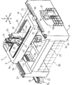
上記右側のコラム本体16には作業者が出入り可能な大きさを有する作業用開口16aが形成されており、該開口16aには機内と機外とを仕切る不図示の開閉ドアが配設されている。また上記作業用開口16a内のドア外側には操作パネル37が配設されている。   The right column body 16 is formed with a working opening 16a having a size that allows an operator to enter and exit. The opening 16a is provided with an opening / closing door (not shown) that separates the inside of the machine from the outside of the machine. Yes. An operation panel 37 is disposed outside the door in the work opening 16a.

上記左側のコラム本体15の外側壁には多数の工具Tnを保持する工具マガジン38が配設されている。また上記コラム本体15の工具交換位置に臨む部分には工具交換窓15aが形成されており、この工具交換窓15aを介して主軸2に装着された加工済み工具Tと、上記工具マガジン38に保持された次工程工具とを不図示の工具交換アームにより自動的に交換するようになっている。   A tool magazine 38 for holding a number of tools Tn is disposed on the outer wall of the left column body 15. Further, a tool change window 15a is formed at a portion of the column main body 15 facing the tool change position, and the processed tool T mounted on the spindle 2 is held by the tool magazine 38 through the tool change window 15a. The tool for the next process is automatically changed by a tool changing arm (not shown).

上記加工テーブル5の左,右側端部には、図5に示すように、クランプ装置45が長手方向に所定間隔をあけて配置固定されており、各クランプ装置45は油圧シリンダ46にクランプロッド47を進退自在に挿入配置した概略構造のものである。このクランプロッド47を幅広長尺ワークWの左,右外縁部に係合させて下降させることにより、幅広長尺ワークWを加工テーブル5に位置決め固定している。また上記加工テーブル5には幅広長尺ワークWの下面を支持する治具49が配置されている。   As shown in FIG. 5, clamp devices 45 are arranged and fixed at predetermined intervals in the longitudinal direction at the left and right end portions of the processing table 5, and each clamp device 45 is connected to a hydraulic cylinder 46 with a clamp rod 47. It is the thing of the general | schematic structure which inserted and arrange | positioned so that it could advance and retract. By engaging and lowering the clamp rod 47 with the left and right outer edges of the wide elongated workpiece W, the wide elongated workpiece W is positioned and fixed to the processing table 5. Further, a jig 49 for supporting the lower surface of the wide and long workpiece W is disposed on the processing table 5.

上記左,右のコラム本体15,16と前,後のクロスフレーム17,18と加工テーブル5とで形成された前,後の開口8a,8bには加工中の切り屑やクーラントが機外に飛散するのを防止する遮蔽機構50が配設されており、該遮蔽機構50は以下の構成となっている。   The front and rear openings 8a and 8b formed by the left and right column main bodies 15 and 16 and the front and rear cross frames 17 and 18 and the processing table 5 have chips and coolant being processed outside the machine. A shielding mechanism 50 for preventing scattering is provided, and the shielding mechanism 50 has the following configuration.

上記遮蔽機構50は、図4及び図5に示すように、左,右のコラム本体15,16間に渡って延びる棒材55に多数の帯板状のカーテンプレート56を懸吊支持し、上記棒材55の両端部に左,右のシリンダ機構(駆動機構)57のピストンロッド58を連結した構成となっている。上記シリンダ機構57は上記左,右のコラム本体15,16の前,後の各外壁面に取付け固定されている。   As shown in FIGS. 4 and 5, the shielding mechanism 50 suspends and supports a large number of strip-like car templates 56 on a bar 55 extending between the left and right column bodies 15 and 16. A piston rod 58 of a left and right cylinder mechanism (drive mechanism) 57 is connected to both ends of the bar 55. The cylinder mechanism 57 is fixedly attached to the front and rear outer wall surfaces of the left and right column bodies 15 and 16.

上記各シリンダ機構57は、シリンダ59内に不図示のピストンを摺動自在に挿入配置し、該ピストンに上記ピストンロッド58を接続した構造ものであり、上記前,後のシリンダ機構57により棒材55を介してカーテンプレート56を前,後の開口8a,8bをそれぞれ略閉塞する閉位置と、該各開口8a,8bを略開放する開位置との間で昇降駆動するようになっている。   Each cylinder mechanism 57 has a structure in which a piston (not shown) is slidably inserted in a cylinder 59, and the piston rod 58 is connected to the piston. A rod member is formed by the front and rear cylinder mechanisms 57. 55, the car template 56 is driven up and down between a closed position where the front and rear openings 8a and 8b are substantially closed and an open position where the openings 8a and 8b are substantially opened.

上記各カーテンプレート56は、図4に示すように、上記各開口8a,8bの上側半部を覆う上側プレート51と、下側半部を覆う下側プレート52とを備えており、上側プレート51の上端部が上記棒材55に取付け固定されている。   As shown in FIG. 4, each car template 56 includes an upper plate 51 that covers the upper half of each of the openings 8 a and 8 b and a lower plate 52 that covers the lower half. Is attached and fixed to the bar 55.

そして上記上側プレート51の下端部にはストッパ部51aが屈曲形成されている。また下側プレート52の上端部には環状の係合部52aが形成されている。該係合部52aに上記上側プレート51が挿通され、また係合部52aは上記ストッパ部51aに当接して該下側プレート52の下端位置を規制するようになっている。これにより下側プレート52は上側プレート51により上下方向に移動可能に支持されている。カーテンプレート56が閉位置に下降し、下側プレート52がワークWに当接すると該下側プレート52はその位置に停まり、もって幅広長尺ワークWの幅方向各部の高さ位置が異なるのを吸収するようになっている。   A stopper 51 a is bent at the lower end of the upper plate 51. An annular engaging portion 52 a is formed at the upper end portion of the lower plate 52. The upper plate 51 is inserted into the engaging portion 52a, and the engaging portion 52a is in contact with the stopper portion 51a to regulate the lower end position of the lower plate 52. Accordingly, the lower plate 52 is supported by the upper plate 51 so as to be movable in the vertical direction. When the car template 56 is lowered to the closed position and the lower plate 52 comes into contact with the workpiece W, the lower plate 52 stops at that position, and the height position of each part in the width direction of the wide and long workpiece W is different. To absorb.

本実施形態のガントリ形マシニングセンタ1でワーク加工を行うには、幅広長尺ワークWを加工テーブル5に搭載し、治具49により支持するとともに各クランプ装置45により位置決め固定する。次に退避している加工ユニット3を第1加工エリアa1に移動させて位置決め固定し、前,後のカーテンプレート56を下降させる。すると下側プレート52が幅広長尺ワークWaの上面に幅方向に順次当接し、さらに閉位置まで下降すると下側プレート52はワーク当接位置に停まって上方に相対移動し、これによりワークWの各部の高さ位置の差異を吸収し、もってワーク上方の開口8a,8bが遮蔽される。なお、ワークWの幅方向外側に位置する残りの下側プレート52は加工テーブル5上に近接する下端位置まで下降する。   In order to perform workpiece machining with the gantry machining center 1 of the present embodiment, a wide and long workpiece W is mounted on the machining table 5, supported by a jig 49, and positioned and fixed by each clamp device 45. Next, the retracted machining unit 3 is moved to the first machining area a1, positioned and fixed, and the front and rear car templates 56 are lowered. Then, the lower plate 52 sequentially contacts the upper surface of the wide and long workpiece Wa in the width direction. When the lower plate 52 is further lowered to the closed position, the lower plate 52 stops at the workpiece contact position and relatively moves upward. The differences in the height positions of the respective parts are absorbed, so that the openings 8a and 8b above the workpiece are shielded. The remaining lower plate 52 located on the outer side in the width direction of the workpiece W is lowered to the lower end position close to the processing table 5.

この状態で主軸2をX軸,Y軸,Z軸方向に相対移動させつつ工具Tにより幅広長尺ワークWに所定の加工を施す。この場合、コラム8の前,後の開口8a,8bはそれぞれ上側,下側プレート51,52で覆われており、加工中の切り屑やクーラントが機外に飛散することはない。   In this state, the tool T performs a predetermined process on the wide and long workpiece W while relatively moving the main shaft 2 in the X-axis, Y-axis, and Z-axis directions. In this case, the front and rear openings 8a and 8b of the column 8 are covered with the upper and lower plates 51 and 52, respectively, so that chips and coolant during processing are not scattered outside the machine.

上記ワーク加工が終了すると加工ユニット3を次の加工エリアa2に移動させ、該加工エリアa2にて上記同様に開口8a,8bをカーテンプレート56で覆い、主軸2によるワーク加工を行う。このようにして加工エリアa1〜a4毎に加工ユニット3を順次移動させ、各加工エリアa1〜a4にて主軸2によるワーク加工を行う。具体的には、例えば電車やバス等の大型車両ボディに所定間隔ごとに窓をくり抜いて形成したり、各窓孔の外周部にボルト孔等を形成したりする場合に好適である。   When the workpiece machining is completed, the machining unit 3 is moved to the next machining area a2, the openings 8a and 8b are covered with the car template 56 in the machining area a2, and the workpiece machining by the spindle 2 is performed. In this manner, the machining unit 3 is sequentially moved for each machining area a1 to a4, and the workpiece machining by the spindle 2 is performed in each machining area a1 to a4. Specifically, it is suitable when, for example, a large-sized vehicle body such as a train or a bus is formed by hollowing a window at a predetermined interval, or a bolt hole or the like is formed on the outer periphery of each window hole.

本実施形態によれば、コラム8を左,右コラム本体15,16の前,後壁面同士を前,後のクロスフレーム17,18で結合してなるものとし、該前,後のクロスフレーム17,18と左,右のコラム本体15,16と加工テーブル5とで形成された前,後の開口8a,8bに多数のカーテンプレート56からなる遮蔽機構50を配設したので、主軸2の加工領域の左,右側方はコラム本体15,16により遮蔽されており、従って左,右のコラム本体15,16と前,後のクロスフレーム17,18により形成された前,後の開口8a,8bだけを遮蔽すればよく、従来の機械本体の外周全体を遮蔽する場合に比べて遮蔽機構50を小型化でき、コスト上昇を抑制できる。   According to the present embodiment, the column 8 is formed by connecting the left and right column main bodies 15 and 16 in front, the rear wall surfaces with the front and rear cross frames 17 and 18, and the front and rear cross frames 17. , 18 and the left and right column bodies 15, 16 and the machining table 5, the front and rear openings 8a, 8b are provided with shielding mechanisms 50 made up of a large number of car templates 56. The left and right sides of the region are shielded by the column bodies 15 and 16, and therefore the front and rear openings 8a and 8b formed by the left and right column bodies 15 and 16 and the front and rear cross frames 17 and 18, respectively. The shielding mechanism 50 can be reduced in size compared with the conventional case where the entire outer periphery of the machine body is shielded, and an increase in cost can be suppressed.

本実施形態では、上記コラム8を加工テーブル5の加工エリアa1〜a4毎に移動可能とし、カーテンプレート56を幅広長尺ワークWに当接して前,後の開口8a,8bを略閉塞する閉位置と、該開口8a,8bを開放する開位置との間で昇降駆動したので、加工テーブル5に搭載された幅広長尺ワークWの加工を行う際のワーク上方の開口8a,8bを確実に遮蔽することができる。   In this embodiment, the column 8 can be moved for each of the processing areas a1 to a4 of the processing table 5, and the car template 56 is brought into contact with the wide and long workpiece W to close the front and rear openings 8a and 8b. Since it is driven up and down between the position and the open position where the openings 8a and 8b are opened, the openings 8a and 8b above the workpiece when the wide and long workpiece W mounted on the machining table 5 is machined are surely formed. Can be shielded.

本実施形態では、棒材55に懸吊支持された多数の帯板状カーテンプレート56をシリンダ機構57により昇降駆動したので、遮蔽機構50を簡単な構造で、かつ特別な設置スペースを設けることなく配置できるとともに、コラム8を移動させる際にカーテンプレート56がワークWに干渉するのを防止できる。   In the present embodiment, since a large number of strip plate-like car templates 56 suspended and supported by the bar 55 are driven up and down by the cylinder mechanism 57, the shielding mechanism 50 has a simple structure and without providing a special installation space. In addition to the arrangement, the car template 56 can be prevented from interfering with the workpiece W when the column 8 is moved.

上記カーテンプレート56を棒材55に支持された上側プレート51と該上側プレート51に上下移動可能に支持された下側プレート52とから構成したので、幅方向各部で高さ位置の異なる幅広長尺ワークWの加工を行う際のワーク上方の開口8a,8bを自動的にかつ簡単な構造で確実に遮蔽することができる。   Since the car template 56 is composed of the upper plate 51 supported by the bar 55 and the lower plate 52 supported by the upper plate 51 so as to be movable up and down, the wide template is different in height position in each part in the width direction. The openings 8a and 8b above the workpiece when machining the workpiece W can be automatically and reliably shielded with a simple structure.

図7は、本発明の第2実施形態による遮蔽部材を説明するための図であり、図中、図5と同一符号は同一又は相当部分を示す。   FIG. 7 is a view for explaining a shielding member according to the second embodiment of the present invention, in which the same reference numerals as those in FIG. 5 denote the same or corresponding parts.

本実施形態の遮蔽機構60は、左,右のコラム本体15,16間に所定間隔をあけて3つのシリンダ機構57を配置し、該各シリンダ機構57のピストンロッド58に棒材61を固定し、各棒材61に多数のカーテンプレート62を上下移動可能に懸吊支持して構成されている。なお、各シリンダ機構57は上記クロスフレーム17,18に取付け固定されている。   In the shielding mechanism 60 of this embodiment, three cylinder mechanisms 57 are arranged with a predetermined interval between the left and right column bodies 15 and 16, and the rod 61 is fixed to the piston rod 58 of each cylinder mechanism 57. Each bar 61 is constructed by suspending and supporting a large number of car templates 62 so as to be vertically movable. Each cylinder mechanism 57 is fixedly attached to the cross frames 17 and 18.

上記各シリンダ機構57は、各棒材61を介してカーテンプレート62を閉位置と開位置との間でそれぞれ独立して昇降駆動する。上記棒材61が下降してカーテンプレート62がワークに当接するとそのカーテンプレート62はその当接位置に停まることとなる。このようにして上記開口8a,8bを遮蔽することができる。   Each cylinder mechanism 57 drives the car template 62 up and down independently between the closed position and the open position via each bar 61. When the bar 61 descends and the car template 62 comes into contact with the workpiece, the car template 62 stops at the contact position. In this way, the openings 8a and 8b can be shielded.

本実施形態では、3つのシリンダ機構57により各カーテンプレート62をそれぞれ独立して昇降駆動するようにしたので、開口8a,8bのうち必要な部分だけを開閉でき、開口面積の大きい大型の工作機械に採用する場合の作業性を向上できる。   In the present embodiment, each car template 62 is driven up and down independently by the three cylinder mechanisms 57, so that only necessary portions of the openings 8a and 8b can be opened and closed, and a large machine tool having a large opening area. It is possible to improve the workability when employed in the above.

本発明の第1実施形態によるガントリ形マシニングセンタの全体斜視図である。1 is an overall perspective view of a gantry type machining center according to a first embodiment of the present invention. 上記ガントリ形マシニングセンタの全体斜視図である。It is a whole perspective view of the said gantry type machining center. 上記ガントリ形マシニングセンタの加工ユニットの斜視図である。It is a perspective view of the processing unit of the said gantry type machining center. 上記加工ユニットに配設された遮蔽部材の断面側面図である。It is a cross-sectional side view of the shielding member arranged in the processing unit. 上記遮蔽部材の正面図である。It is a front view of the said shielding member. 上記加工ユニットの主軸部分の斜視図である。It is a perspective view of the main-axis part of the said processing unit. 本発明の第2実施形態による遮蔽部材の正面図である。It is a front view of the shielding member by a 2nd embodiment of the present invention.

符号の説明Explanation of symbols

1 ガントリ形マシニングセンタ(工作機械)
2 主軸
8 コラム
8a,8b 開口
15,16 コラム本体
17,18 クロスフレーム
50,60 遮蔽機構
51 上側プレート
52 下側プレート
55,61 棒材
56,62 カーテンプレート
57 シリンダ機構(駆動機構)
1 Gantry machining center (machine tool)
2 Main shaft 8 Column 8a, 8b Opening 15, 16 Column body 17, 18 Cross frame 50, 60 Shielding mechanism 51 Upper plate 52 Lower plate 55, 61 Bar material 56, 62 Car template 57 Cylinder mechanism (drive mechanism)

Claims (6)

工具が装着された主軸を相対移動させることにより加工テーブルに搭載されたワークに所定の加工を施すようにした工作機械において、上記主軸を加工ユニットにより上記加工テーブルに対してX軸,Y軸,Z軸方向に相対移動可能に支持し、該加工ユニットに切り屑やクーラントが加工エリア外に飛散するのを防止する遮蔽機構を設けたことを特徴とする工作機械。   In a machine tool configured to perform predetermined machining on a workpiece mounted on a machining table by relatively moving a spindle on which a tool is mounted, the spindle is moved with respect to the machining table by an X-axis, a Y-axis, A machine tool that is supported so as to be relatively movable in the Z-axis direction, and is provided with a shielding mechanism that prevents chips and coolant from scattering outside the processing area. 請求項1において、上記加工ユニットは、上記加工テーブルの左,右に立設された左,右のコラム本体の前,後端部同士を前,後のクロスフレームで結合してなるコラムを備え、上記主軸は、該前,後のクロスフレームと上記左,右のコラム本体とで囲まれた部分に軸線を略鉛直に向けて配置されており、上記遮蔽機構は、上記前,後のクロスフレームに上下動可能に吊設され、上記コラム本体,クロスフレーム及び加工テーブルで形成された前,後の開口を開閉する前,後の遮蔽部材を備えていることを特徴とする工作機械。   2. The processing unit according to claim 1, wherein the processing unit includes a column formed by connecting front and rear end portions of the left and right column bodies erected on the left and right of the processing table with front and rear cross frames. The main shaft is disposed in a portion surrounded by the front and rear cross frames and the left and right column main bodies with the axis line oriented substantially vertically, and the shielding mechanism includes the front and rear cross A machine tool, comprising a shielding member that is suspended from a frame so as to be movable up and down, and that opens and closes front and rear openings formed by the column main body, the cross frame, and a processing table. 請求項2において、上記加工テーブルは一方向に配置された複数の加工エリアを有し、上記加工ユニットは、上記加工エリアの配置方向に延びる長尺状のベッド上に該加工エリア配置方向に移動可能に搭載され、何れかの加工エリアに位置決めされた状態で上記主軸をX軸,Y軸及びZ軸方向に移動させることにより上記ワークの加工を行うように構成されており、上記前,後の遮蔽部材は、上記加工ユニットを何れかの加工エリアに位置決めした状態で上記前,後の開口を開閉するように構成されていることを特徴とする工作機械。   3. The machining table according to claim 2, wherein the machining table has a plurality of machining areas arranged in one direction, and the machining unit moves in the machining area arrangement direction on a long bed extending in the arrangement direction of the machining area. The workpiece can be machined by moving the spindle in the X-axis, Y-axis, and Z-axis directions while being positioned in any machining area. The shielding member is configured to open and close the front and rear openings in a state where the processing unit is positioned in any processing area. 請求項2又は3において、上記遮蔽部材は、上記左,右のコラム本体間に渡るように配設された前,後の棒材に多数の帯板状カーテンプレートを懸吊支持し、該棒材を駆動機構により上記開口を略閉塞する閉位置と開放する開位置との間で昇降駆動するように構成されていることを特徴とする工作機械。   4. The shield member according to claim 2, wherein the shielding member suspends and supports a large number of strip-like car templates on the front and rear bar members arranged to extend between the left and right column bodies. A machine tool configured to drive a material up and down between a closed position in which the opening is substantially closed and an open position in which the material is opened by a drive mechanism. 請求項4において、上記各カーテンプレートは、上記棒材に上下移動可能に吊り下げられており、上記棒材を閉位置に下降させるとワークに当接した位置に停まることを特徴とする工作機械。   5. The machine tool according to claim 4, wherein each car template is suspended from the bar so as to be vertically movable, and stops at a position in contact with a workpiece when the bar is lowered to a closed position. machine. 請求項4又は5において、上記各カーテンプレートは、上記棒材に支持された上側プレートと該上側プレートに上下方向に移動可能に支持された下側プレートとから構成されており、上記棒材を閉位置に下降させると下側プレートはワークに当接した位置に停まることを特徴とする工作機械。   6. The car template according to claim 4, wherein each car template includes an upper plate supported by the bar and a lower plate supported by the upper plate so as to be movable in the vertical direction. A machine tool characterized in that when the lower plate is lowered to the closed position, the lower plate stops at a position in contact with the workpiece.
JP2004112683A 2004-04-07 2004-04-07 Machine Tools Withdrawn JP2005297085A (en)

Priority Applications (1)

Application Number Priority Date Filing Date Title
JP2004112683A JP2005297085A (en) 2004-04-07 2004-04-07 Machine Tools

Applications Claiming Priority (1)

Application Number Priority Date Filing Date Title
JP2004112683A JP2005297085A (en) 2004-04-07 2004-04-07 Machine Tools

Publications (1)

Publication Number Publication Date
JP2005297085A true JP2005297085A (en) 2005-10-27

Family

ID=35329256

Family Applications (1)

Application Number Title Priority Date Filing Date
JP2004112683A Withdrawn JP2005297085A (en) 2004-04-07 2004-04-07 Machine Tools

Country Status (1)

Country Link
JP (1) JP2005297085A (en)

Cited By (1)

* Cited by examiner, † Cited by third party
Publication number Priority date Publication date Assignee Title
CN112659200A (en) * 2020-11-16 2021-04-16 江苏悦达兴业汽车配件有限公司 Automobile spare and accessory part cutting equipment with cooling function

Cited By (1)

* Cited by examiner, † Cited by third party
Publication number Priority date Publication date Assignee Title
CN112659200A (en) * 2020-11-16 2021-04-16 江苏悦达兴业汽车配件有限公司 Automobile spare and accessory part cutting equipment with cooling function

Similar Documents

Publication Publication Date Title
US7255519B2 (en) Machine tool
JP5708825B2 (en) Machine Tools
JP4745612B2 (en) Machine Tools
JP6199511B1 (en) Combined processing apparatus and combined processing method
JP6604592B2 (en) Machine Tools
JPWO2018047301A1 (en) Machine Tools
US7509718B1 (en) Machine tool with selective drive motor positioning
JP4410002B2 (en) Machine Tools
JP2014058032A (en) Machine tool having protective cover
JP2018027612A (en) Composite machining apparatus
CN104411453A (en) Machine tool
JP5332153B2 (en) Machine tool with loader
JPH0899302A (en) Gantry type machine tool
JP5171111B2 (en) Pallet changer
EP1795298A1 (en) Machine tool with loading device
JP2010179418A (en) Machining device
JP2005297085A (en) Machine Tools
JP2002154026A (en) Attachment storage device
JP2001205541A (en) Machine Tools
JP5201473B2 (en) Machine tool body cover
JP2006255845A (en) Machine tool
KR101045553B1 (en) Wood processing machine
JP4522684B2 (en) Machine Tools
CN223406576U (en) A CNC gantry milling machine with a structure for preventing waste chips from splashing outward
KR101671858B1 (en) Door system for machining center

Legal Events

Date Code Title Description
A621 Written request for application examination

Effective date: 20070314

Free format text: JAPANESE INTERMEDIATE CODE: A621

A761 Written withdrawal of application

Free format text: JAPANESE INTERMEDIATE CODE: A761

Effective date: 20080611