JP2005297084A - Machine tool - Google Patents
Machine tool Download PDFInfo
- Publication number
- JP2005297084A JP2005297084A JP2004112682A JP2004112682A JP2005297084A JP 2005297084 A JP2005297084 A JP 2005297084A JP 2004112682 A JP2004112682 A JP 2004112682A JP 2004112682 A JP2004112682 A JP 2004112682A JP 2005297084 A JP2005297084 A JP 2005297084A
- Authority
- JP
- Japan
- Prior art keywords
- machining
- workpiece
- axis
- processing
- spindle
- Prior art date
- Legal status (The legal status is an assumption and is not a legal conclusion. Google has not performed a legal analysis and makes no representation as to the accuracy of the status listed.)
- Withdrawn
Links
Images

Landscapes
- Jigs For Machine Tools (AREA)
- Machine Tool Units (AREA)
Abstract
【課題】幅広長尺ワークを加工する場合の加工精度を確保できる工作機械を提供する。
【解決手段】工具Tが装着された主軸2を相対移動させることにより加工テーブル5に搭載されたワークWに所定の加工を施すようにした工作機械において、上記主軸2を加工ユニット3により上記加工テーブル5に対してX軸,Y軸,Z軸方向に相対移動可能に支持し、該加工ユニット3に上記ワークWを加工テーブル5に押圧固定するワーク押え装置40を設ける。
【選択図】 図3A machine tool capable of ensuring machining accuracy when machining a wide and long workpiece is provided.
In a machine tool configured to perform predetermined machining on a workpiece W mounted on a machining table 5 by relatively moving a spindle 2 on which a tool T is mounted, the spindle 2 is machined by a machining unit 3. A work pressing device 40 that supports the table 5 so as to be relatively movable in the X-axis, Y-axis, and Z-axis directions and presses and fixes the work W to the processing table 5 is provided in the processing unit 3.
[Selection] Figure 3
Description
本発明は、工具が装着された主軸をX軸,Y軸,Z軸方向に相対移動させることにより加工テーブルに搭載されたワークに所定の加工を施すようにした工作機械に関する。 The present invention relates to a machine tool that performs predetermined machining on a workpiece mounted on a machining table by relatively moving a spindle on which a tool is mounted in the X-axis, Y-axis, and Z-axis directions.
比較的長尺のワークを加工するためのガントリ形マシニングセンタとして、例えば、特許文献1又は2に記載されたものがある。特許文献1のものは、長尺状のベッド2に門形のコラム7をX軸方向に移動可能に配設し、該コラム7のクロスレール7cの前面にサドル25をY軸方向に移動可能に配設し、該サドル25にラム30をZ軸方向に移動可能に配設し、該ラム30に、工具32が装着された主軸31を配設した構造となっている。
As a gantry type machining center for processing a relatively long workpiece, for example, there is one described in
この種のマシニングセンタでは、ベッド2上に比較的長尺のワークWを搭載し、コラム7,サドル25,ラム30をそれぞれX軸,Y軸,Z軸方向に相対移動させて主軸31により上記ワークWに所定の加工を行うようになっている。
ところで、上記従来の工作機械において、加工テーブルの略全域に渡るような大きさの幅広長尺ワークを加工する場合、ワークの外縁部のみが固定されているだけであるから、ワーク中央部分での固定が十分でなくなり、該中央部分の加工精度にこのワーク固定方法が悪影響を与えるという懸念がある。 By the way, in the above-mentioned conventional machine tool, when processing a wide and long workpiece having such a size as to cover almost the entire area of the processing table, only the outer edge portion of the workpiece is fixed, There is a concern that this work fixing method will adversely affect the machining accuracy of the central portion because the fixing is not sufficient.
本発明は、上記従来の実情に鑑みてなされたもので、幅広長尺ワークを加工する場合の加工精度を確保できる工作機械を提供することを目的としている。 The present invention has been made in view of the above-described conventional situation, and an object of the present invention is to provide a machine tool capable of ensuring machining accuracy when machining a wide and long workpiece.
請求項1の発明は、工具が装着された主軸を相対移動させることにより加工テーブルに搭載されたワークに所定の加工を施すようにした工作機械において、上記主軸を加工ユニットにより上記加工テーブルに対してX軸,Y軸,Z軸方向に相対移動可能に支持し、該加工ユニットに、上記ワークを加工テーブルに対して押圧固定するワーク押え装置を設けたことを特徴としている。 According to the first aspect of the present invention, in a machine tool configured to perform a predetermined process on a workpiece mounted on a machining table by relatively moving a spindle on which a tool is mounted, the spindle is moved with respect to the machining table by a machining unit. The workpiece holding device is provided that supports the workpiece so as to be relatively movable in the X-axis, Y-axis, and Z-axis directions, and presses and fixes the workpiece against the machining table.
請求項2の発明は、請求項1において、上記ワーク押え装置は、上記加工ユニットに装着され、シリンダによりピストンロッドを進退自在に支持する複数のシリンダ機構を備えており、上記各ピストンロッドの先端部には上記ワークの形状に追随するよう取付姿勢又は形状を変化させつつ上記ワークを押圧するパッド部材が装着されていることを特徴としている。 According to a second aspect of the present invention, in the first aspect, the work presser device includes a plurality of cylinder mechanisms that are attached to the processing unit and that support the piston rod by a cylinder so that the piston rod can be advanced and retracted. A pad member that presses the workpiece while changing its mounting posture or shape so as to follow the shape of the workpiece is mounted on the part.
請求項3の発明は、請求項1又は2において、上記加工テーブルは一方向に配置された複数の加工エリアを有し、上記加工ユニットは、上記加工エリアの配置方向に延びる長尺状のベッド上に該加工エリア配置方向に移動可能に搭載され、何れかの加工エリアに位置決めされた状態で上記主軸をX軸,Y軸及びZ軸方向に移動させることにより上記ワークの加工を行うように構成されており、上記ワーク押え装置は、ワークの上記加工エリア部分のみを押圧固定するように構成されていることを特徴としている。
The invention of
請求項4の発明は、請求項3において、上記加工ユニットは、上記加工テーブルを跨ぐように上記ベッド上に配設されており、上記加工テーブルには各加工エリアの略全域に渡る大きさ,形状を有する幅広長尺ワークが搭載されており、上記シリンダ機構は、上記加工ユニットの上記加工テーブルを跨ぐ梁部材に略垂直下方に向けて配設され、上記ワークを垂直下方に押圧固定していることを特徴としている。
The invention of claim 4 is the invention according to
請求項1の発明に係る工作機械によれば、主軸を支持する加工ユニットにワークを加工テーブルに対して押圧固定するワーク押え装置を設けたので、幅広長尺ワークであってもワーク全体を加工テーブルに確実に固定することができ、加工精度を確保できる。 According to the machine tool of the first aspect of the present invention, since the work pressing device that presses and fixes the work against the work table is provided in the work unit that supports the spindle, the entire work is processed even for a wide and long work. It can be securely fixed to the table, ensuring machining accuracy.
請求項2の発明では、各シリンダ機構のピストンロッドにワーク形状に追随するよう取付姿勢が変化するパッド部材を装着したので、ワークに傾斜面や凹凸があっても確実に該ワークを加工テーブルに押圧固定することができる。
In the invention of
請求項3の発明では、加工ユニットを何れかの加工エリアに位置決めした状態で主軸によるワーク加工を行うようにしたので、幅広長尺ワークであっても該ワークの加工エリア部分だけを押圧固定するだけで良く、ワーク全体を押圧する場合に比べてワーク押え装置を小型かつ簡単な構造にできる。
In the invention of
請求項4の発明では、加工ユニットの加工テーブルを跨ぐ梁部材にシリンダ機構を取り付けてワークを加工テーブル上に押圧固定したので、各加工エリアの略全域に渡るような大きさ,形状を有する幅広長尺ワークであっても該ワークの中央部分を確実に押圧固定でき、該中央部分を加工する場合の加工精度を確保することができる。 In the invention of claim 4, since the cylinder mechanism is attached to the beam member straddling the processing table of the processing unit and the workpiece is pressed and fixed on the processing table, the wide width having a size and shape over almost the entire processing area. Even in the case of a long workpiece, the central portion of the workpiece can be reliably pressed and fixed, and the processing accuracy when processing the central portion can be ensured.
以下、本発明の実施の形態を添付図面に基づいて説明する。 Hereinafter, embodiments of the present invention will be described with reference to the accompanying drawings.
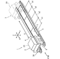
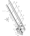
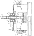
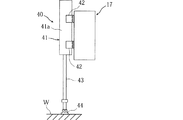
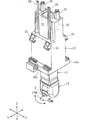
図1ないし図6は、本発明の一実施形態によるガントリ形マシニングセンタ(工作機械)を説明するための図であり、図1はガントリ形マシニングセンタの全体斜視図、図2はガントリ形マシニングセンタの加工ユニットの斜視図、図3,図4はワーク押え装置を備えた加工ユニットの正面図,断面側面図、図5はワーク押え装置の側面図、図6は加工ユニットの主軸部分の斜視図である。 1 to 6 are views for explaining a gantry type machining center (machine tool) according to an embodiment of the present invention. FIG. 1 is an overall perspective view of the gantry type machining center, and FIG. 2 is a processing unit of the gantry type machining center. FIGS. 3 and 4 are a front view and a cross-sectional side view of a machining unit provided with a workpiece pressing device, FIG. 5 is a side view of the workpiece pressing device, and FIG. 6 is a perspective view of a main shaft portion of the machining unit.
図において、1はガントリ形マシニングセンタを示しており、これは工具Tが装着された主軸2をX軸,Y軸,Z軸の3軸方向に相対移動可能に支持する加工ユニット3と、該加工ユニット3を上記X軸方向と平行なU軸方向(加工エリア配置方向)に移動可能に支持する左,右一対のベッド4,4とから構成されている。
In the figure, reference numeral 1 denotes a gantry machining center, which includes a
上記左,右のベッド4,4の間には加工テーブル5が配置されている。この加工テーブル5は、長さが20〜30mで幅が3〜5mに渡る大形のものであり、上記U軸方向に配置された複数の加工エリアa1〜a4を有している。また上記左,右のベッド4,4のU軸方向両端部には加工テーブル5のU軸方向外側に位置するよう加工ユニット3の退避スペースが設けられており、該退避スペースに加工ユニット3を位置させた状態で幅広長尺ワークWを上下方向に着脱できるようになっている。
A processing table 5 is disposed between the left and right beds 4 and 4. The machining table 5 is a large one having a length of 20 to 30 m and a width of 3 to 5 m, and has a plurality of machining areas a1 to a4 arranged in the U-axis direction. Further, a retreat space for the
上記加工ユニット3は、機械正面から上記U軸方向に見たとき、加工テーブル5を跨ぐように左,右のベッド4,4に搭載された門形コラム8と、該コラム8によりX軸方向に移動可能に支持されたクロスレール9と、該クロスレール9によりY軸方向に移動可能に支持されたサドル10と、該サドル10によりZ軸方向に移動可能に支持されたラム11とを備えており、該ラム11の下端に上記主軸2が軸線を概ね垂直方向に向けて配設されている。
The
上記ラム11は、図6に示すように、主軸2を軸直角回りのA軸方向に回転割り出し駆動するとともに、主軸2を軸線回りのC軸方向に回転割り出し駆動する回転割り出し装置13を備えており、これにより5軸制御によるワーク加工が行えるようになっている。
As shown in FIG. 6, the
上記門形コラム8は、左,右のベッド4上に配置された側面視略長方形状の左,右のコラム本体15,16の前壁,後壁同士を前,後のクロスフレーム17,18により一体的に結合した構造となっている。上記左,右のコラム本体15,16は各ベッド4,4の上面に配設された一対のU軸ガイドレール19,19により上記U軸方向に移動可能に支持されている。
The
上記クロスレール9は、上下方向に開口した矩形箱状のものからなり、平面視で、上記左,右のコラム本体15,16及び前,後のクロスフレーム17,18とで囲まれた空間内に配置されている。またクロスレール9の左右上縁部にはフランジ部9a,9aが形成されており、該左,右のフランジ部9aが各コラム本体15,16の上面に配設されたX軸ガイドレール21,21によりX軸方向に移動可能に支持されている。
The
上記サドル10は、上下方向に開口する角筒状のものからなり、上記クロスレール9内に配置されている。このサドル10の前,後壁にはそれぞれ一対の三角ブラケット25,25が取付け固定されており、この前,後の各ブラケット25,25がクロスレール9の前,後上面に配設されたY軸ガイドレール26,26によりY軸方向に移動可能に支持されている。
The
また上記サドル10の前,後壁の下縁にはフランジ部10a,10aが形成されており、該前,後のフランジ部10aがクロスレール9の前,後下面に配設されたY軸ガイドレール27,27によりY軸方向に移動可能に支持されている。このようにしてサドル10は上,下のY軸ガイドレール26,27により挟持されている。
Further,
上記ラム11は、上下方向に延びる角筒状のものであり、上記サドル10内に配置されている。このラム11はこれの前後,左右壁の4面が上記サドル10の各内壁面に配設されたすべり面(不図示)を介してZ軸方向に移動可能に支持されている。なお、29はラム11のZ軸方向位置を検出するスケールである。
The
上記X軸及びY軸ストロークは3〜4m程度に設定され、Z軸ストロークは1〜2m程度に設定されている。また上記クロスレール9,サドル10及びラム11はそれぞれボールねじ30,31、32及びサーボモータ33,34,35により往復駆動される。また図示していないが、上記加工ユニット3は、U軸駆動装置により上記U軸方向に往復駆動される。
The X-axis and Y-axis strokes are set to about 3 to 4 m, and the Z-axis stroke is set to about 1 to 2 m. The
上記右側のコラム本体16には作業者が出入り可能な大きさを有する作業用開口16aが形成されており、該開口16aには機内と機外とを仕切る不図示の開閉ドアが配設されている。また上記作業用開口16a内のドア外側には操作パネル37が配設されている。
The
上記左側のコラム本体15の外側壁には多数の工具Tnを保持する工具マガジン38が配設されている。また上記コラム本体15の交換位置に臨む部分には工具交換窓15aが形成されており、この工具交換窓15aを介して主軸2に装着された加工済み工具Tと、上記工具マガジン38に保持された次工程工具とを不図示の工具交換アームにより自動的に交換するようになっている。
A
上記加工テーブル5の左,右側端部には、図3に示すように、クランプ装置45が長手方向に所定間隔をあけて配置されている。この各クランプ装置45は油圧シリンダ46によりクランプロッド47を進退自在に支持した概略構造のものである。このクランプロッド47を幅広長尺ワークWの左,右外縁部Wa,Wbに係合させて下降させることにより、幅広長尺ワークWを加工テーブル5に位置決め固定している。また上記加工テーブル5には幅広長尺ワークWの下面を支持する治具49が配置されている。
As shown in FIG. 3,
上記加工ユニット3には、図3ないし図5に示すように、幅広長尺ワークWを加工テーブル5に押圧固定するワーク押え装置40が配設されており、該ワーク押え装置40は以下の構造となっている。
As shown in FIGS. 3 to 5, the
上記コラム8の加工テーブル5を跨ぐように位置する前,後のクロスフレーム(梁部材)17,18の前,後壁面にはそれぞれ4つのシリンダ機構41が所定間隔をあけて配設されており、各シリンダ機構41は幅広長尺ワークWの加工エリア部分のU軸方向前,後端部における幅方向両端部及び中央部に臨む位置に配置されている。
Four
上記各シリンダ機構41はこれのシリンダ41aが上,下一対のブラケット42,42により上記クロスフレーム17,18にボルト締め固定されている。この各シリンダ機構41は、シリンダ41a内に摺動自在に挿入されたピストン(不図示)にピストンロッド43を接続してなり、該各ピストンロッド43は各シリンダ41aに圧縮空気を供給することにより昇降駆動される。
Each
上記各ピストンロッド43の下端部にはスラストパッド(パッド部材)44が装着されている。このスラストパッド44はワークWの傾斜面や凹凸に追随するようその取付姿勢及び形状が変化するようになっている。
A thrust pad (pad member) 44 is attached to the lower end of each
上記各シリンダ機構41への圧縮空気の供給圧力は幅広長尺ワークWを十分に固定可能で、かつ該ワークWを変形させることのない値に制御される。なお、各シリンダ機構41を幅広長尺ワークWの大きさ等に応じて個別又はグループ毎に制御しても良い。
The supply pressure of the compressed air to each
本実施形態のガントリ形マシニングセンタ1でワーク加工を行うには、幅広長尺ワークWを加工テーブル5の治具49上に搭載して支持するとともに各クランプ装置45により位置決め固定する。次に退避スペースにある加工ユニット3を第1加工エリアa1に移動させて位置決め固定する。
In order to perform workpiece machining with the gantry machining center 1 of the present embodiment, a wide and long workpiece W is mounted on and supported on a
そして上記各シリンダ機構41に圧縮空気を供給してピストンロッド43を下降させ、幅広長尺ワークWを加工テーブル5上に押圧固定する。この場合、スラストパッド44が幅広長尺ワークWの傾斜面に追随するよう取付姿勢を変化させて傾斜し、あるいはさらに変形しつつワークWを押圧することとなる。これにより幅広長尺ワークWの第1加工エリアa1の外周部は左,右のクランプ装置45と前,後の各シリンダ機構41により押圧固定される。この状態で主軸2をX軸,Y軸,Z軸方向に相対移動させつつ工具Tにより幅広長尺ワークWに所定の加工が施される。
Then, compressed air is supplied to each
上記ワーク加工が終了すると、各ピストンロッド43を上昇させて幅広長尺ワークWの押圧を解除し、加工ユニット3を次の加工エリアa2に移動させ、該加工エリアa2にて上記同様に加工ユニット3を位置決め固定するとともに、各シリンダ機構41により幅広長尺ワークWを押圧固定し、主軸2によるワーク加工が行なわれる。このようにして加工エリアa1〜a4毎に加工ユニット3を順次移動させ、各加工エリアa1〜a4にて主軸2によるワーク加工が行なわれる。具体的には、例えば電車やバス等の大型車両ボディに所定間隔ごとに窓をくり抜いて形成したり、各窓孔の外周部にボルト孔等を形成したりする場合に好適である。
When the workpiece machining is completed, each
このように本実施形態によれば、主軸2をX,Y,Z軸方向に移動可能に支持する加工ユニット3に幅広長尺ワークWの加工エリア部分を加工テーブル5に押圧固定するワーク押え装置40を設けたので、幅広長尺ワークWの固定が困難な中央部分に加工を施す場合の加工精度を確保できる。
As described above, according to the present embodiment, the work pressing device that presses and fixes the processing area portion of the wide long workpiece W to the processing table 5 to the
本実施形態では、各シリンダ機構41のピストンロッド43にワーク形状に追随するよう取付姿勢が変化するスラストパッド44を装着したので、上記幅広長尺ワークWに傾斜面や凹凸があっても該ワークWを確実に加工テーブル5に押圧固定することができる。
In this embodiment, since the
また上記加工ユニット3を加工テーブル5の各加工エリアa1〜a4毎に移動させ、各加工エリアa1〜a4内にて主軸2によるワーク加工を行うようにしたので、ワークの加工エリアa1〜a4部分だけを押圧固定すれば済み、長尺ワーク全体を押圧する場合に比べてワーク押え装置40を小型化でき、また構造が簡単で済む。
Further, since the
1 ガントリ形マシニングセンタ(工作機械)
2 主軸
3 加工ユニット
5 加工テーブル
17,18 クロスフレーム(梁部材)
40 ワーク押え装置
41 シリンダ機構
41a シリンダ
43 ピストンロッド
44 スラストパッド(パッド部材)
W 幅広長尺ワーク
1 Gantry machining center (machine tool)
2
40
W Wide and long workpiece
Claims (4)
Priority Applications (1)
| Application Number | Priority Date | Filing Date | Title |
|---|---|---|---|
| JP2004112682A JP2005297084A (en) | 2004-04-07 | 2004-04-07 | Machine tool |
Applications Claiming Priority (1)
| Application Number | Priority Date | Filing Date | Title |
|---|---|---|---|
| JP2004112682A JP2005297084A (en) | 2004-04-07 | 2004-04-07 | Machine tool |
Publications (1)
| Publication Number | Publication Date |
|---|---|
| JP2005297084A true JP2005297084A (en) | 2005-10-27 |
Family
ID=35329255
Family Applications (1)
| Application Number | Title | Priority Date | Filing Date |
|---|---|---|---|
| JP2004112682A Withdrawn JP2005297084A (en) | 2004-04-07 | 2004-04-07 | Machine tool |
Country Status (1)
| Country | Link |
|---|---|
| JP (1) | JP2005297084A (en) |
Cited By (2)
| Publication number | Priority date | Publication date | Assignee | Title |
|---|---|---|---|---|
| CN104369022A (en) * | 2014-11-19 | 2015-02-25 | 经纬纺织机械股份有限公司 | Auxiliary floating supporting device for machining large castings and sheet type parts |
| WO2026074769A1 (en) * | 2024-10-04 | 2026-04-09 | 村田機械株式会社 | Machine tool |
-
2004
- 2004-04-07 JP JP2004112682A patent/JP2005297084A/en not_active Withdrawn
Cited By (2)
| Publication number | Priority date | Publication date | Assignee | Title |
|---|---|---|---|---|
| CN104369022A (en) * | 2014-11-19 | 2015-02-25 | 经纬纺织机械股份有限公司 | Auxiliary floating supporting device for machining large castings and sheet type parts |
| WO2026074769A1 (en) * | 2024-10-04 | 2026-04-09 | 村田機械株式会社 | Machine tool |
Similar Documents
| Publication | Publication Date | Title |
|---|---|---|
| US7172375B2 (en) | Machine tool | |
| JP4854131B2 (en) | Equipment for performing manufacturing processes on processed products | |
| JP3442590B2 (en) | Punching machine and machining method | |
| US20080178447A1 (en) | Machining center | |
| EP2708312B1 (en) | Machining center | |
| CN102046327A (en) | Machine tool | |
| JP6693777B2 (en) | Work processing device | |
| JP4410002B2 (en) | Machine Tools | |
| CN113070505A (en) | Multi-spindle efficient drilling and milling machine tool and drilling method thereof | |
| JPH0346252B2 (en) | ||
| JP2009178804A (en) | Machine tool having a boring bar magazine and boring bar magazine | |
| KR20170009060A (en) | Apparatus for changing a workpiece of a turning center | |
| JP3165158U (en) | Machine tool with a boring bar magazine | |
| JPH0899302A (en) | Gantry type machine tool | |
| JP6537546B2 (en) | Machining system | |
| JP2005297084A (en) | Machine tool | |
| JP5171111B2 (en) | Pallet changer | |
| JPH0577124A (en) | Shape steel machining machine | |
| CN103153510B (en) | Crankshaft milling machine | |
| KR20100094407A (en) | Drilling machine for processing holes | |
| JP2011110622A (en) | Production line and machine tool | |
| CN210551286U (en) | A double-station fixture mounted on a manipulator | |
| JPH0531639A (en) | Machining device for long workpiece | |
| CN206185489U (en) | Lathe of cutter side formula | |
| JP3810388B2 (en) | Double-sided milling machine |
Legal Events
| Date | Code | Title | Description |
|---|---|---|---|
| A621 | Written request for application examination |
Free format text: JAPANESE INTERMEDIATE CODE: A621 Effective date: 20070315 |
|
| A761 | Written withdrawal of application |
Effective date: 20080611 Free format text: JAPANESE INTERMEDIATE CODE: A761 |