JP2005297080A - Robot device and robot joint device - Google Patents
Robot device and robot joint device Download PDFInfo
- Publication number
- JP2005297080A JP2005297080A JP2004112597A JP2004112597A JP2005297080A JP 2005297080 A JP2005297080 A JP 2005297080A JP 2004112597 A JP2004112597 A JP 2004112597A JP 2004112597 A JP2004112597 A JP 2004112597A JP 2005297080 A JP2005297080 A JP 2005297080A
- Authority
- JP
- Japan
- Prior art keywords
- preload
- robot
- joint
- leaf spring
- bearing
- Prior art date
- Legal status (The legal status is an assumption and is not a legal conclusion. Google has not performed a legal analysis and makes no representation as to the accuracy of the status listed.)
- Pending
Links
Images

Landscapes
- Toys (AREA)
- Manipulator (AREA)
- Support Of The Bearing (AREA)
Abstract
【課題】 ロボット装置の落下時・転倒時に衝撃力を緩和して減速機並びにアクチュエータ・モータを保護することができるベアリングの予圧機構を構成する。
【解決手段】 リング状の板バネを利用し、板バネの弾性を利用してベアリングに一定圧力の予圧をかける機構を採用する。板バネは連結する部位の重量を十分支持できる軸方向の弾性力を発生できるような形状に構成する。そして、板バネの弾性力は落下・衝撃時に過大なモーメント又は外力が作用した場合、予圧を行う板バネに塑性変形が生じないように設計する。勿論、通常動作時にも板バネ部の弾性力で与えたベアリング予圧力で高い剛性で関節を保持できるようにする。
【選択図】 図4
PROBLEM TO BE SOLVED: To provide a bearing preload mechanism capable of protecting a speed reducer and an actuator / motor by relaxing an impact force when a robot apparatus is dropped or falls.
A mechanism that applies a preload of a constant pressure to a bearing by utilizing the elasticity of a leaf spring is employed using a ring-like leaf spring. The leaf spring is configured in a shape that can generate an elastic force in the axial direction that can sufficiently support the weight of the connected portion. The elastic force of the leaf spring is designed so that plastic deformation does not occur in the leaf spring that performs preload when an excessive moment or external force is applied during dropping or impact. Of course, the joint can be held with high rigidity by the bearing preload given by the elastic force of the leaf spring portion even during normal operation.
[Selection] Figure 4
Description
本発明は、例えば2足歩行や4足歩行を始めとするロボット装置並びにロボットの関節装置に係り、特に、腕や脚など少なくとも1つの関節駆動部はアクチュエータ・モータ及び減速機で構成されるロボット装置並びにロボットの関節装置に関する。 The present invention relates to a robot apparatus and a robot joint apparatus including, for example, biped walking and quadruped walking, and in particular, a robot in which at least one joint driving unit such as an arm or a leg is composed of an actuator motor and a speed reducer. The present invention relates to a device and a robot joint device.
さらに詳しくは、本発明は、アクチュエータ・モータ及び減速機を回動可能に軸支する回転軸支持構造に用いられるベアリング部分を適当な圧力によりアクチュエータの軸方向に保持する予圧機構を備えているロボット装置並びにロボットの関節装置に係り、特に、十分な回転精度と剛性を得るとともに、ロボット装置の落下時・転倒時やその他の関節部に過大な外力が印加された場合において衝撃力を吸収又は緩和して減速機並びにアクチュエータ・モータを保護するベアリングの予圧機構を備えたロボット装置並びにロボットの関節装置に関する。 More specifically, the present invention relates to a robot having a preload mechanism for holding a bearing portion used in a rotating shaft support structure for pivotally supporting an actuator / motor and a speed reducer in an axial direction of the actuator with an appropriate pressure. In particular, it is necessary to obtain sufficient rotational accuracy and rigidity, and to absorb or mitigate impact force when the robot device is dropped or overturned or when excessive external force is applied to other joints. The present invention relates to a robot apparatus having a bearing preload mechanism that protects a reduction gear and an actuator / motor, and a robot joint apparatus.
最近、イヌやネコのように4足歩行の動物の身体メカニズムやその動作を模したペット型ロボット、あるいは、ヒトのような2足直立歩行を行なう動物の身体メカニズムや動作をモデルにしてデザインされた「人間形」若しくは「人間型」と呼ばれるロボット(humanoid robot)など、脚式移動ロボットに関する研究開発が進展し、実用化への期待も高まってきている。 Recently designed as a model of the body mechanism and movement of a pet-type robot that mimics the body mechanism and movement of a quadruped animal, such as a dog or a cat, or the animal that performs biped upright walking, such as a human. Further, research and development on legged mobile robots such as robots called “humanoids” or “humanoids” have progressed, and expectations for practical use are also increasing.
この種の脚式移動ロボットは、一般に、多数の関節自由度を備え、関節の動きをアクチュエータ・モータで実現するようになっている。また、各モータの回転位置、回転量などを取り出して、サーボ制御を行なうことにより、所望の動作パターンを再現するとともに、姿勢制御を行なうようになっている。 This type of legged mobile robot generally has a large number of joint degrees of freedom, and the movement of the joint is realized by an actuator motor. Further, by extracting the rotation position and rotation amount of each motor and performing servo control, a desired operation pattern is reproduced and posture control is performed.
また、アクチュエータ・モータから高出力トルクを得るために、モータの出力端に減速部を設けるのが一般的である。減速部には、例えば遊星歯車機構(例えば、特許文献1を参照のこと)が適用される。遊星歯車機構は、恒星としての太陽歯車と、惑星としての遊星歯車と、遊星歯車の公転軌道を規定する内歯歯車で構成される歯車構造であり、この他に、遊星歯車の軸中心をつなぐ遊星キャリアを備えている。遊星歯車機構を用いた減速機によれば、駆動軸と同軸上で減速をすることが可能なため、複段数の連結により強力な減速比を得ることができる。 Further, in order to obtain a high output torque from the actuator / motor, it is common to provide a speed reduction portion at the output end of the motor. For example, a planetary gear mechanism (see, for example, Patent Document 1) is applied to the speed reduction unit. The planetary gear mechanism is a gear structure composed of a sun gear as a star, a planetary gear as a planet, and an internal gear that defines the revolution orbit of the planetary gear. In addition, the planetary gear mechanism connects the axis centers of the planetary gears. Has a planetary carrier. According to the speed reducer using the planetary gear mechanism, it is possible to reduce the speed on the same axis as the drive shaft, so that a strong reduction ratio can be obtained by connecting multiple stages.
一般に、回転自由度を持つ機械装置においては、アクチュエータ・モータ及び減速機の回転軸部分を回動可能に軸支するために、ボール・ベアリングなどが用いられる(例えば、特許文献2を参照のこと)。さらに、回転軸の回転精度を向上させるために、2個のボール・ベアリングを対向させて配設することが多い(例えば、図8を参照のこと)。 In general, in a mechanical device having a degree of freedom of rotation, a ball bearing or the like is used to pivotally support a rotation shaft portion of an actuator / motor and a speed reducer (see, for example, Patent Document 2). ). Further, in order to improve the rotation accuracy of the rotating shaft, two ball bearings are often arranged facing each other (see, for example, FIG. 8).
また、このように2個以上のボール・ベアリングを組み合わせて構成される回転軸支持構造においては、これらの回転軸の軸方向に対するガタを防止するために、これらベアリング部分を適当な圧力によりアクチュエータの軸方向に保持する予圧機構を装備するのが一般的である。 Further, in the rotary shaft support structure configured by combining two or more ball bearings in this way, in order to prevent backlash with respect to the axial direction of these rotary shafts, these bearing portions are attached to the actuator by an appropriate pressure. It is common to equip a preload mechanism that holds in the axial direction.
通常機械の場合は、一旦据え付けられると、(移設されるまで)その場で稼動し続け、自ら移動しない。したがって、その回転部支持構造においてベアリングを使用する場合、その与圧機構に関しては剛性設計と寿命設計などを考慮すれば十分である。例えば図9に示すように、アクチュエータ・モータ又は減速機の回転軸を軸支するためにその軸端に設けられた1対のボール・ベアリングを、軸端を覆う蓋体を軸方向に所定量だけ捩じ込んで、適当な予圧をボール・ベアリングに与える、という方法が一般採用されている。 In the case of a normal machine, once installed, it continues to operate on the spot (until it is relocated) and does not move by itself. Therefore, when a bearing is used in the rotating part support structure, it is sufficient to consider the rigidity design and life design for the pressurizing mechanism. For example, as shown in FIG. 9, a pair of ball bearings provided at the end of the shaft to support the rotation shaft of the actuator / motor or speed reducer, and a lid covering the shaft end in a predetermined amount in the axial direction. Generally, a method of applying only a suitable preload to the ball bearing is employed.
通常の機械装置においては、回転部の剛性としては、軸方向のみを考慮すればよく、それ以外の不規則な方向へ印加されるモーメントを考慮する必要はない。また、回転部支持構造における剛性のみを考慮すればよく、過度の加重やモーメントが印加された場合における衝撃の緩和や吸収といった事柄を考慮する必要はない。 In a normal mechanical device, only the axial direction needs to be considered as the rigidity of the rotating portion, and there is no need to consider the moment applied in other irregular directions. Further, only the rigidity of the rotating part support structure needs to be considered, and there is no need to consider matters such as shock relaxation and absorption when an excessive load or moment is applied.
これに対し、アクチュエータ・モータ並びにその減速機がエンターテインメント・ロボットにおける腕や脚などの可動部の関節駆動部に適用された場合には、機械自らが移動するために、転倒や衝突による自分へのダメージを考慮した機械設計が求められる。 On the other hand, when the actuator / motor and its speed reducer are applied to the joint drive part of a movable part such as an arm or leg in an entertainment robot, the machine itself moves, so Mechanical design considering damage is required.
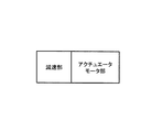
図10には、アクチュエータ・モータ並びに減速機からなる関節駆動部を、2足歩行のエンターテインメント・ロボットの肩関節(ピッチ軸)に適用している様子を示している。この場合、腕を用いて予想外に重たい物体を持ち上げようとする場合や、落下時や転倒時において腕を床に着いて保護動作を行なおうとするような場合には(例えば、特許文献3を参照のこと)、過度の加重やモーメントが関節駆動部に印加されることになる。 FIG. 10 shows a state in which a joint drive unit including an actuator / motor and a speed reducer is applied to a shoulder joint (pitch axis) of a biped walking entertainment robot. In this case, when trying to lift an unexpectedly heavy object using the arm, or when trying to perform a protective operation by putting the arm on the floor when falling or falls (for example, Patent Document 3) ), An excessive load or moment is applied to the joint drive unit.
図11には、ロボット装置の腕や脚部などの関節駆動部に適用されたアクチュエータに対して印加される力やモーメントを表している。図示の通り、ロボット装置の関節駆動部に適用されるアクチュエータにおいては、落下や転倒時において、軸方向の力FzやモーメントMxやMvなど、従来の機械装置においては考慮する必要のない力やモーメントが印加される。 FIG. 11 shows forces and moments applied to an actuator applied to a joint drive unit such as an arm or a leg of the robot apparatus. As shown in the figure, the actuator applied to the joint drive unit of the robot apparatus does not need to be considered in the conventional mechanical apparatus such as the axial force F z , moment M x, and M v when dropping or overturning. A force or moment is applied.
また、アクチュエータ・モータ若しくは減速機の出力軸に印加された過度の衝撃力や衝撃モーメントが減速機やアクチュエータ・モータに直接伝達されると、これら機器の破損、破壊を招来し、修理や部品の交換を余儀なくされてしまう。 In addition, if excessive impact force or impact moment applied to the output shaft of the actuator / motor or reducer is directly transmitted to the reducer / actuator / motor, these devices may be damaged or It will be forced to exchange.
転倒や衝突によって発生する外力やモーメントはロボット各部位の中でも特に関節部の回転支持構造に激しく作用し、性能に悪影響を与えることになる。 An external force or moment generated by a fall or a collision acts violently on the rotation support structure of the joint portion among the robot parts, and adversely affects performance.
このため、ロボット装置の関節駆動部に用いられる場合、アクチュエータ・モータ並びに減速機の回転部支持に使用されるベアリングに圧力を与える予圧機構は、従来通りに剛性設計と寿命設計を考慮するだけでは不十分であり、図9に示したようなベアリングの予圧機構は不適当である。すなわち、ベアリングの予圧機構として、過度の衝撃力や衝撃モーメントを緩和又は吸収する衝撃吸収の作用効果を備えていなければならない、と本発明者らは思料する。勿論、ロボット装置の小型化設計を実現するためには、アクチュエータ・モータと減速機の合計で、より軸長が短くなるような予圧機構の構成であることが望ましい。 For this reason, when used in a joint drive unit of a robot apparatus, a preload mechanism that applies pressure to a bearing used to support a rotating unit of an actuator / motor and a speed reducer is not limited to just considering rigidity design and life design as usual. The bearing preload mechanism as shown in FIG. 9 is inadequate. That is, the present inventors consider that the preload mechanism of the bearing must have an impact absorption effect that relieves or absorbs excessive impact force and impact moment. Of course, in order to realize a miniaturized design of the robot apparatus, it is desirable that the preload mechanism has a configuration in which the shaft length is further shortened in total of the actuator / motor and the speed reducer.
関節駆動部の動力源としてのアクチュエータには、ロボット装置の上位制御層より必要な駆動電力が供給され、これに従ってアクチュエータが作動し、ロボットの装置動作が実現する。 Necessary drive power is supplied from the upper control layer of the robot apparatus to the actuator as a power source of the joint drive unit, and the actuator operates in accordance with this to realize the apparatus operation of the robot.
他方、ロボット装置に対し外力が印加された場合、とりわけ急激な変化をする力(撃力)が加わった場合に発生する歯部の過大な応力、電気回路に発生する逆起電力などに十分耐える設計が必要になる。 On the other hand, when an external force is applied to the robotic device, it is sufficiently resistant to excessive stress on the teeth, especially when a force that changes suddenly (shocking force) is applied, back electromotive force generated in the electric circuit, etc. Design is required.
電気的には電気回路上の逆起電力に耐えるような回路構成を考案すればよい。機械的には回転方向の過大なトルクを逃がす装置としてトルクリミッタという衝撃緩衝機構を内部に設けることが考えられるが、図11に示したようなモーメントや軸力には効果がない。 Electrically, a circuit configuration that can withstand the counter electromotive force on the electric circuit may be devised. Mechanically, it is conceivable to provide an impact buffer mechanism called a torque limiter as a device for releasing excessive torque in the rotational direction. However, there is no effect on the moment and axial force as shown in FIG.
そこで、与えられた撃力が印加されても、減速機の内歯やピニオンの歯部に過大な応力が発生しないような構成のアクチュエータ設計が望まれる、という訳である。 Therefore, it is desirable to design an actuator that does not generate excessive stress on the internal teeth of the speed reducer and the teeth of the pinion even when a given impact force is applied.
本発明の目的は、腕や脚など少なくとも1つの関節駆動部がアクチュエータ・モータ及び減速機により好適に構成される、優れたロボット装置並びにロボットの関節装置を提供することにある。 An object of the present invention is to provide an excellent robot apparatus and robot joint apparatus in which at least one joint drive unit such as an arm or a leg is preferably configured by an actuator motor and a speed reducer.
本発明のさらなる目的は、アクチュエータ・モータ及び減速機を回動可能に軸支する回転軸支持構造に用いられるベアリング部分を適当な圧力によりアクチュエータの軸方向に保持することができる予圧機構を備えている、優れたロボット装置並びにロボットの関節装置を提供することにある。 It is a further object of the present invention to provide a preload mechanism capable of holding the bearing portion used in the rotating shaft support structure for pivotally supporting the actuator / motor and the speed reducer in the axial direction of the actuator with an appropriate pressure. Another object of the present invention is to provide an excellent robot apparatus and a robot joint apparatus.
本発明のさらなる目的は、十分な回転精度と剛性を得るとともに、ロボット装置の落下時・転倒時やその他の関節部に過大な外力が印加された場合において衝撃力を吸収又は緩和して減速機並びにアクチュエータ・モータを保護することができるベアリングの予圧機構を備えた、優れたロボット装置並びにロボットの関節装置を提供することにある。 A further object of the present invention is to obtain sufficient rotational accuracy and rigidity, and to reduce or reduce the impact force by absorbing or mitigating impact force when the robot apparatus is dropped or falls or when excessive external force is applied to other joints. It is another object of the present invention to provide an excellent robot apparatus and a robot joint apparatus having a bearing preload mechanism capable of protecting an actuator / motor.
本発明は、上記課題を参酌してなされたものであり、複数の関節部を備えたロボット装置において、
関節を駆動するアクチュエータのモータ部と、
前記モータ部の出力端に配設された減速部と、
前記減速部の出力軸を軸支する軸受部と、
前記軸受部を軸方向の弾性力により一定圧力の予圧を与える予圧部と、
を具備することを特徴とするロボット装置である。
The present invention has been made in consideration of the above problems, and in a robot apparatus having a plurality of joints,
A motor part of an actuator that drives the joint;
A speed reduction portion disposed at an output end of the motor portion;
A bearing that pivotally supports the output shaft of the speed reduction unit;
A preload portion that applies a preload of a constant pressure to the bearing portion by an axial elastic force;
A robot apparatus comprising:
ここで、前記減速部は、例えば、恒星としての太陽歯車と、惑星としての遊星歯車と、遊星歯車の公転軌道を規定する内歯歯車からなる遊星歯車機構により構成される。遊星歯車機構を用いた減速機によれば、駆動軸と同軸上で減速をすることが可能なため、複段数の連結により強力な減速比を得ることができる。 Here, the speed reduction part is configured by a planetary gear mechanism including, for example, a sun gear as a star, a planetary gear as a planet, and an internal gear that defines the revolution orbit of the planetary gear. According to the speed reducer using the planetary gear mechanism, it is possible to reduce the speed on the same axis as the drive shaft, so that a strong reduction ratio can be obtained by connecting multiple stages.
また、前記軸受部は、軸方向に対向する1対のボール・ベアリングにより構成され、前記予圧部は、軸方向に弾性力を持つリング状の板バネで構成される。 Further, the bearing portion is constituted by a pair of ball bearings opposed in the axial direction, and the preload portion is constituted by a ring-shaped leaf spring having an elastic force in the axial direction.
そして、前記予圧部は、通常の運動の負荷条件において、前記関節部を十分に高い剛性で保持できる大きさに予圧が設定されており、過大なモーメント力の作用を前記弾性力で吸収することができる。また、前記予圧部は、想定している衝撃力がなくなった後には、予圧状態が元の状態に復帰するような弾性特性を持つので、大きな力(モーメント)の回避を可能にすることができる。 The preload portion is set to a size capable of holding the joint portion with sufficiently high rigidity under normal motion load conditions, and absorbs the action of an excessive moment force with the elastic force. Can do. Further, since the preload portion has an elastic characteristic that the preload state returns to the original state after the assumed impact force is lost, it is possible to avoid a large force (moment). .
脚式移動ロボットを始めとする多関節型のロボット装置においては、関節の動きをアクチュエータ・モータで実現し、さらにアクチュエータ・モータから高出力トルクを得るために、遊星歯車機構などで構成される減速機がモータ部の出力端に取り付けられる。 In articulated robots such as legged mobile robots, joint movements are realized with actuators and motors, and in order to obtain high output torque from actuators and motors, a reduction gear composed of a planetary gear mechanism, etc. A machine is attached to the output end of the motor section.
また、アクチュエータ・モータ及び減速機の回転軸部分を回動可能に軸支するために、例えばボール・ベアリングのような軸受けが用いられる。そして、このような回転軸支持構造においては、回転軸の軸方向に対するガタを防止するために、これらベアリング部分を適当な圧力によりアクチュエータの軸方向に保持する予圧機構が必要となる。 Further, a bearing such as a ball bearing is used to pivotally support the rotation shaft portions of the actuator / motor and the speed reducer. And in such a rotating shaft support structure, in order to prevent the backlash with respect to the axial direction of a rotating shaft, the preload mechanism which hold | maintains these bearing parts in the axial direction of an actuator with a suitable pressure is needed.
ここで、アクチュエータ・モータ並びにその減速機がエンターテインメント・ロボットにおける腕や脚などの可動部の関節駆動部に適用された場合には、機械自らが移動するために、転倒や衝突による自分へのダメージを考慮した機械設計が求められる。このため、ロボット装置の関節駆動部においては、ベアリングに圧力を与える予圧機構は、従来通りに剛性設計と寿命設計を考慮するだけでは不十分であり、過度の衝撃力や衝撃モーメントを緩和又は吸収する衝撃吸収の作用効果を備えている必要がある。 Here, if the actuator / motor and its speed reducer are applied to the joint drive part of a movable part such as an arm or leg in an entertainment robot, the machine itself will move, causing damage to itself due to a fall or collision. Mechanical design that takes into account For this reason, in the joint drive part of the robot apparatus, it is not sufficient to consider the rigid design and life design as usual for the preload mechanism that applies pressure to the bearings, and to reduce or absorb excessive impact force and impact moment. It is necessary to have the effect of shock absorption.
そこで、本発明では、リング状の板バネを利用して、板バネの弾性を利用してベアリングに一定圧力の予圧をかける機構を採用する。この板バネは連結する部位の重量を十分支持できる軸方向の弾性力を発生できるような形状に構成する。そして、板バネの弾性力は落下・衝撃時に過大なモーメント又は外力が作用した場合、予圧を行う板バネに塑性変形が生じないように設計する。勿論、通常動作時にも板バネ部の弾性力で与えたベアリング予圧力で高い剛性で関節を保持できるようにする。 Therefore, the present invention employs a mechanism that uses a ring-shaped plate spring to apply a preload of a constant pressure to the bearing using the elasticity of the plate spring. The leaf spring is configured in a shape that can generate an elastic force in the axial direction that can sufficiently support the weight of the connected portion. The elastic force of the leaf spring is designed so that plastic deformation does not occur in the leaf spring that performs preload when an excessive moment or external force is applied during dropping or impact. Of course, the joint can be held with high rigidity by the bearing preload given by the elastic force of the leaf spring portion even during normal operation.
したがって、本発明に係る回転部支持構造によれば、エンターテイメントロボットの動力源であるアクチュエータにおいて歩行中の転倒や衝突の際にロボットの腕や脚の関節に作用する過大な外力(モーメント)から、与圧機構の弾性力による衝撃緩和作用によって、アクチュエータや減速機を保護することができる。また、通常の動作時においては、ベアリングに対し十分な予圧を与えて、関節を高い剛性に保持することができる。 Therefore, according to the rotating part support structure according to the present invention, from an excessive external force (moment) acting on the arm and leg joint of the robot in the event of a fall or collision during walking in the actuator that is the power source of the entertainment robot, The actuator and the speed reducer can be protected by the impact mitigating action by the elastic force of the pressurizing mechanism. In addition, during normal operation, a sufficient preload can be applied to the bearing to keep the joint highly rigid.
本発明によれば、腕や脚など少なくとも1つの関節駆動部がアクチュエータ・モータ及び減速機により好適に構成される、優れたロボット装置並びにロボットの関節装置を提供することができる。 According to the present invention, it is possible to provide an excellent robot apparatus and robot joint apparatus in which at least one joint drive unit such as an arm or a leg is preferably configured by an actuator motor and a speed reducer.
また、本発明によれば、アクチュエータ・モータ及び減速機を回動可能に軸支する回転軸支持構造に用いられるベアリング部分を適当な圧力によりアクチュエータの軸方向に保持することができる予圧機構を備えている、優れたロボット装置並びにロボットの関節装置を提供することができる。 In addition, according to the present invention, a preload mechanism is provided that can hold the bearing portion used in the rotating shaft support structure that pivotally supports the actuator / motor and the speed reducer in the axial direction of the actuator with an appropriate pressure. It is possible to provide an excellent robot apparatus and a robot joint apparatus.
また、本発明によれば、十分な回転精度と剛性を得るとともに、ロボット装置の落下時・転倒時やその他の関節部に過大な外力が印加された場合において衝撃力を吸収又は緩和して減速機並びにアクチュエータ・モータを保護することができるベアリングの予圧機構を備えた、優れたロボット装置並びにロボットの関節装置を提供することができる。 In addition, according to the present invention, sufficient rotational accuracy and rigidity can be obtained, and when the robot apparatus is dropped or falls, or when an excessive external force is applied to other joints, the impact force is absorbed or reduced to reduce the speed. It is possible to provide an excellent robot apparatus and a robot joint apparatus having a bearing preload mechanism capable of protecting the machine and the actuator / motor.
本発明によれば、エンターテイメント・ロボットの関節アクチュエータの減速機出力軸に設けられたベアリング予圧機構において、板バネ部の弾性力によって予圧を与えることにより、以下のような効果を得ることができる。すなわち、
(1)通常動作時には、板バネ部の弾性力で与えたベアリング予圧力により、関節を高い剛性で保持することができる。
(2)ロボット装置が落下又は衝撃するときには、関節駆動部に印加される過大なモーメント力の作用を板バネの弾性力で吸収し、アクチュエータや減速機の損傷を回避することができる。
(3)関節機構を小型・省スペースで設計することができる。
According to the present invention, in the bearing preloading mechanism provided on the speed reducer output shaft of the joint actuator of the entertainment robot, the following effects can be obtained by applying the preload by the elastic force of the leaf spring portion. That is,
(1) During normal operation, the joint can be held with high rigidity by the bearing pre-pressure given by the elastic force of the leaf spring portion.
(2) When the robot apparatus drops or impacts, the excessive moment force applied to the joint drive unit can be absorbed by the elastic force of the leaf spring, and damage to the actuator and the speed reducer can be avoided.
(3) The joint mechanism can be designed in a compact and space-saving manner.
本発明のさらに他の目的、特徴や利点は、後述する本発明の実施形態や添付する図面に基づくより詳細な説明によって明らかになるであろう。 Other objects, features, and advantages of the present invention will become apparent from more detailed description based on embodiments of the present invention described later and the accompanying drawings.
以下、図面を参照しながら本発明の実施形態について詳解する。 Hereinafter, embodiments of the present invention will be described in detail with reference to the drawings.
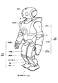
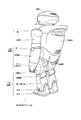
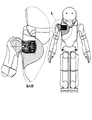
図1及び図2には、本発明の一実施形態に係る動作編集システムによる動作編集となる脚式移動ロボットの外観構成を示している。この脚式移動ロボットは、「人間形」又は「人間型」と呼ばれ、図示の通り、脚式移動ロボットは、胴体部と、頭部と、左右の上肢部と、脚式移動を行なう左右2足の下肢部とで構成され、例えば胴体に内蔵されている制御部(図示しない)により機体の動作を統括的にコントロールするようになっている。 1 and 2 show an external configuration of a legged mobile robot that performs motion editing by the motion editing system according to an embodiment of the present invention. This legged mobile robot is called "human form" or "human form", and as shown in the figure, the legged mobile robot has a torso, a head, left and right upper limbs, and left and right legs that perform legged movement. It consists of two leg parts, for example, and controls the operation of the aircraft in an integrated manner by a control unit (not shown) built in the torso, for example.
左右各々の下肢は、大腿部と、膝関節と、脛部と、足首と、足平とで構成され、股関節によって体幹部の略最下端にて連結されている。また、左右各々の上肢は、上腕と、肘関節と、前腕とで構成され、肩関節によって体幹部の上方の左右各側縁にて連結されている。また、頭部は、首関節によって体幹部の略最上端中央に連結されている。 Each of the left and right lower limbs is composed of a thigh, a knee joint, a shin, an ankle, and a foot, and is connected by a hip joint at the substantially lower end of the trunk. The left and right upper limbs are composed of an upper arm, an elbow joint, and a forearm, and are connected to the left and right side edges above the trunk by shoulder joints. The head is connected to the substantially uppermost center of the trunk by a neck joint.
このように構成された脚式移動ロボットは、制御部による全身協調的な動作制御により、2足歩行を実現することができる。かかる2足歩行は、一般に、以下に示す各動作期間に分割される歩行周期を繰り返すことによって行なわれる。すなわち、 The legged mobile robot configured as described above can realize bipedal walking by whole body cooperative operation control by the control unit. Such biped walking is generally performed by repeating a walking cycle divided into the following operation periods. That is,
(1)右脚を持ち上げた、左脚による単脚支持期
(2)右足が接地した両脚支持期
(3)左脚を持ち上げた、右脚による単脚支持期
(4)左足が接地した両脚支持期
(1) Single leg support period with left leg lifted right leg (2) Both leg support period with right leg grounded (3) Single leg support period with right leg lifted with left leg (4) Both legs with left leg grounded Support period
この脚式移動ロボットの関節自由度は、アクチュエータ・モータを用いて実現され、各モータの回転位置、回転量などを取り出して、サーボ制御を行なうことにより、所望の動作パターンを再現するとともに、姿勢制御を行なうようになっている。すなわち、制御部(図示しない)は、各関節アクチュエータの駆動制御や各センサなどからの外部入力を処理するコントローラ(主制御部)や、電源回路その他の周辺機器類を搭載した筐体である。制御部は、その他、遠隔操作用の通信インターフェースや通信装置を含んでいてもよい。 The degree of freedom of joints of this legged mobile robot is realized by using actuators and motors. By taking out the rotation position and rotation amount of each motor and performing servo control, the desired movement pattern is reproduced and the posture Control is to be performed. In other words, the control unit (not shown) is a housing on which a controller (main control unit) that processes external inputs from each joint actuator, each sensor, and the like, a power supply circuit, and other peripheral devices are mounted. In addition, the control unit may include a communication interface and a communication device for remote operation.
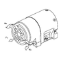
また、アクチュエータ・モータから高出力トルクを得るために、モータ部の出力端に減速部が配設されている(図3を参照のこと)。本実施形態では、減速部には遊星歯車機構が適用される。遊星歯車機構は、恒星としての太陽歯車と、惑星としての遊星歯車と、遊星歯車の公転軌道を規定する内歯歯車で構成される歯車構造であり、この他に、遊星歯車の軸中心をつなぐ遊星キャリアを備えている。遊星歯車機構を用いた減速機によれば、駆動軸と同軸上で減速をすることが可能なため、複段数の連結により強力な減速比を得ることができる。 Further, in order to obtain a high output torque from the actuator / motor, a speed reduction unit is provided at the output end of the motor unit (see FIG. 3). In this embodiment, a planetary gear mechanism is applied to the speed reduction unit. The planetary gear mechanism is a gear structure composed of a sun gear as a star, a planetary gear as a planet, and an internal gear that defines the revolution orbit of the planetary gear. In addition, the planetary gear mechanism connects the axis centers of the planetary gears. Has a planetary carrier. According to the speed reducer using the planetary gear mechanism, it is possible to reduce the speed on the same axis as the drive shaft, so that a strong reduction ratio can be obtained by connecting multiple stages.
ここで、アクチュエータ・モータ及び減速機の回転軸部分を回動可能に軸支するために、例えばボール・ベアリングのような軸受けが用いられる。さらに、回転軸の回転精度を向上させるために、2個のボール・ベアリングを対向させて配設する。また、このように2個以上のボール・ベアリングを組み合わせて構成される回転軸支持構造においては、回転軸の軸方向に対するガタを防止するために、これらベアリング部分を適当な圧力によりアクチュエータの軸方向に保持する予圧機構が必要となる。 Here, for example, a bearing such as a ball bearing is used to pivotally support the rotary shaft portions of the actuator / motor and the speed reducer. Furthermore, in order to improve the rotation accuracy of the rotating shaft, two ball bearings are arranged facing each other. Further, in the rotary shaft support structure configured by combining two or more ball bearings in this way, in order to prevent backlash with respect to the axial direction of the rotary shaft, these bearing portions are moved in the axial direction of the actuator with an appropriate pressure. It is necessary to have a preloading mechanism that holds it.
通常機械の場合は、一旦据え付けられると、(移設されるまで)その場で稼動し続け、自ら移動しない。したがって、その回転部支持構造においてベアリングを使用する場合、その与圧機構に関しては剛性設計と寿命設計などを考慮すれば十分である。また、回転部支持構造における剛性のみを考慮すればよく、過度の加重やモーメントが印加された場合における衝撃の緩和や吸収といった事柄を考慮する必要はない。 In the case of a normal machine, once installed, it continues to operate on the spot (until it is relocated) and does not move by itself. Therefore, when a bearing is used in the rotating part support structure, it is sufficient to consider the rigidity design and life design for the pressurizing mechanism. Further, only the rigidity of the rotating part support structure needs to be considered, and there is no need to consider matters such as shock relaxation and absorption when an excessive load or moment is applied.
これに対し、アクチュエータ・モータ並びにその減速機がエンターテインメント・ロボットにおける腕や脚などの可動部の関節駆動部に適用された場合には、機械自らが移動するために、転倒や衝突による自分へのダメージを考慮した機械設計が求められる。例えば、落下時や転倒時において、過度の加重やモーメントが関節駆動部に印加されることになる。 On the other hand, when the actuator / motor and its speed reducer are applied to the joint drive part of a movable part such as an arm or leg in an entertainment robot, the machine itself moves, so Mechanical design considering damage is required. For example, an excessive load or moment is applied to the joint drive unit when it falls or falls.
このため、ロボット装置の関節駆動部に用いられる場合、アクチュエータ・モータ並びに減速機の回転部支持に使用されるベアリングに圧力を与える予圧機構は、従来通りに剛性設計と寿命設計を考慮するだけでは不十分であり、過度の衝撃力や衝撃モーメントを緩和又は吸収する衝撃吸収の作用効果を備えている必要がある。勿論、ロボット装置の小型化設計を実現するためには、アクチュエータ・モータと減速機の合計で、より軸長が短くなるような予圧機構の構成であることが望ましい。 For this reason, when used in a joint drive unit of a robot apparatus, a preload mechanism that applies pressure to a bearing used to support a rotating unit of an actuator / motor and a speed reducer is not limited to just considering rigidity design and life design as usual. It is inadequate, and it is necessary to have an effect of impact absorption that relaxes or absorbs excessive impact force and impact moment. Of course, in order to realize a miniaturized design of the robot apparatus, it is desirable that the preload mechanism has a configuration in which the shaft length is further shortened in total of the actuator / motor and the speed reducer.
そこで、本実施形態では、リング状の板バネを利用して、板バネの弾性を利用してベアリングに一定圧力の予圧をかける機構を採用する。この板バネは連結する部位の重量を十分支持できる軸方向の弾性力を発生できるような形状に構成する。そして、板バネの弾性力は落下・衝撃時に過大なモーメント又は外力が作用した場合、予圧を行う板バネに塑性変形が生じないように設計する。 Therefore, in the present embodiment, a mechanism that applies a preload of a constant pressure to the bearing by using the elasticity of the leaf spring using a ring-like leaf spring is employed. The leaf spring is configured in a shape that can generate an elastic force in the axial direction that can sufficiently support the weight of the connected portion. The elastic force of the leaf spring is designed so that plastic deformation does not occur in the leaf spring that performs preload when an excessive moment or external force is applied during dropping or impact.
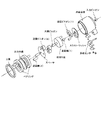
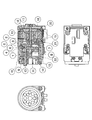
アクチュエータ装置には、駆動源としてのサーボ・モータの出力軸と同軸状に、遊星歯車機構からなる減速部が取り付けらける。図4には、アクチュエータ装置に取り付けられる減速機の分解図を示している。 The actuator device can be attached with a speed reduction unit comprising a planetary gear mechanism coaxially with an output shaft of a servo motor as a drive source. FIG. 4 shows an exploded view of the speed reducer attached to the actuator device.
また、遊星歯車機構は、図示の通り、スラスト・ワッシャー、初段遊星ピニオン、初段遊星軸、取付け板、太陽ピニオン、出段遊星ピニオン、スペーサ、出段遊星軸、一対のベアリングに挟まれた出力太陽、並びに上板が軸方向に配設され、マグネシウム合金からなる上記の減速部ケーシング内に収容されることにより構成される。減速機ケーシングの内周には内歯歯車が形設され、上述した遊星歯車機構の各部品が内蔵されている。 As shown in the figure, the planetary gear mechanism includes a thrust washer, a first stage planetary pinion, a first stage planetary shaft, a mounting plate, a sun pinion, a first stage planetary pinion, a spacer, a first stage planetary shaft, and an output sun sandwiched between a pair of bearings. The upper plate is disposed in the axial direction, and is accommodated in the speed reduction portion casing made of a magnesium alloy. An internal gear is formed on the inner periphery of the reduction gear casing, and each component of the planetary gear mechanism described above is incorporated.
また、減速部のケーシング内部には、サーボ・モータの出力軸の原点を検出するための原点センサやその他の計測機器類も収容される。 In addition, an origin sensor for detecting the origin of the output shaft of the servo motor and other measuring devices are housed inside the casing of the deceleration unit.
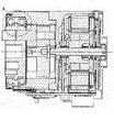
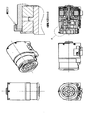
図5には、本発明の一実施形態に係るアクチュエータ装置の軸方向断面構成図を示している。以下、同図を参照しながらアクチュエータ装置の内部構成について説明する。 FIG. 5 shows an axial sectional configuration diagram of an actuator device according to an embodiment of the present invention. Hereinafter, the internal configuration of the actuator device will be described with reference to FIG.
参照番号1は、減速機の内歯ケースである。また、参照番号2は、アクチュエータ・モータのケースである。
これら内歯ケース1及びモータ・ケース2には、それぞれタップ穴を持つ足となる部分か2つずつ配設されており、ロボット装置側の関節部フレームのベース側(図示しない)への取り付けに使用される。
Each of the
参照番号3は、銅ワッシャーであり、初段遊星ピニオン5とモータ・ケース2の間の摩擦を減じるために挿設される。
参照番号4は、入力ピニオンであり、モータの出力軸端に取り付けられている。
参照番号5は、初段遊星ピニオンであり、遊星減速機では2〜4個(通常は3個)が配置される。
参照番号6は、初段遊星軸であり、キャリアプレート7によって圧入固定されている。
参照番号8は、太陽ピニオンである。ここで、キャリアプレート7上野5本の処断優勢軸6と太陽ピニオン8との間の平行度や同心度を十分に高い精度(例えば50μm)に抑えることが、遊星ピニオンや内歯の摩滅を防ぐ上で重要である。
参照番号9は、出段遊星軸であり、出力太陽11によって圧入固定されている。
参照番号10は、出段遊星ピニオンであり、遊星減速機では2〜4個が配置される。
出力太陽11は、ロボットの各部位の駆動対象部品(図示しない)に取り付けられる。
The
参照番号12は、軸方向に対向して配設された1対のボール・ベアリングである。出力太陽11にボール・ベアリング12の内輪を圧入して構成される構成部品を減速機の内歯ケース1内部に挿入する。
参照番号13は、位置決めピンであり、出力太陽11に圧入され、駆動対象部品(前述)との移相関係を決定する。
参照番号14は、リング状の板バネであり、その男性を利用してボール・ベアリング12に対し軸方向の一定圧力の予圧を与えるために使用される。本実施形態では、この板バネ14は連結する部位の重量を十分支持できる軸方向の弾性力を発生できるような形状に構成する。そして、板バネの弾性力は落下・衝撃時に過大なモーメント又は外力が作用した場合、予圧を与える板バネに塑性変形が生じないように構成されている。
参照番号15は、固定子コア巻き線組み立て部品であり、モータ・ケース2に圧入接着固定された上で、駆動時のコイル巻き線の振動を抑制するために粘度の高い接着剤で含浸固定される。
参照番号16は、回転子マグネット組み立て部品であり、段付き軸とマグネットを接着固定した後で、当該マグネットを着磁磁化して使用する。
参照番号17は、駆動基板であり、固定子コア巻き線組み立て部品15の巻き線への駆動電流(モータ電流)を制御する。
参照番号18は、側板であり、モータ内部に収容した臓物に最後に蓋をする。
参照番号19は、ボール・ベアリングであり、回転子16を回動可能に軸支し、その回転を円滑にする。
参照番号20は、通信基板であり、外部システムとの通信と、回転センサ基板21から出力される回転子マグネット16の回転状態の情報を受信し、駆動基板17への信号や電源の供給を行なう。
参照番号21は、回転センサ基板であり、回転子マグネット組み立て基板の端面に取り付けられたマグネットの磁気を検知するホール素子などのセンサを搭載している。
参照番号22は、原点センサであり、回転位相の原点を感知する。
ここで、落下・衝撃時にアクチュエータ外部から出力太陽11を通して大きな力(トルク)が遊星減速機内部に作用する。
Here, a large force (torque) acts on the inside of the planetary reduction gear from the outside of the actuator through the
出力太陽11を押し倒したりしようとするモーメントや軸方向の力などが作用して、内側のベアリング12のレース面に圧痕やついてしまうことがある。また、キャリアプレート7や出段遊星ピニオン10の歯部は、特に強度的に弱いので、歯面に圧痕の形成し、最悪の場合には歯が破損してしまうことになる。
Moments or axial forces that try to push down the
過大なトルクを逃がす装置として、トルクリミッタという衝撃緩衝機構を内部に設けることも、当業者であれば相当される。しかしながら、このような手段は、回転方向の過大なトルクを逃がす機構として作用することはできても、上記のようなモーメントや軸力(図11を参照のこと)には効果がない。 A person skilled in the art can provide an internal shock absorbing mechanism called a torque limiter as a device for releasing excessive torque. However, although such means can act as a mechanism for releasing excessive torque in the rotational direction, it is not effective for the moment and axial force (see FIG. 11) as described above.
そこで、本実施形態では、上述したように、板バネ14のような板材で製作した予圧バネを用いている。板バネ14は、軸方向に可撓性を持ち、その弾性力によりボール・ベアリング12に一定圧力の予圧を与えるように構成されている。
Therefore, in the present embodiment, as described above, a preload spring made of a plate material such as the
ここで、板バネ14により設定する予圧の設定値は、通常の運動の負荷条件では予圧量は関節を十分に高い剛性で保持できる大きさに設定する。このような場合、落下・衝撃時には過大なモーメント力の作用を板バネ14の弾性力で吸収することができる。且つ、想定している衝撃力がなくなった後には、予圧状態が元の状態に復帰するような弾性特性を持つように板厚を設定し、大きな力(モーメント)の回避を可能にすることができる。
Here, the set value of the preload set by the
このように、板バネ14という簡単な部品で予圧を設定することができるので、ベアリングの予圧機構を簡素で且つ省スペースで製作することができる。したがって、減速機を小型に設計することができるメリットがある。
Thus, since the preload can be set with a simple component such as the
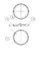
図6には、板バネ16の正面、側面、並びに背面をそれぞれ示している。板バネ14の中で、a部は減速機の内歯ケース1の先端部の凸に引っ掛けて板バネ14を固定する爪を構成する。板バネ14が与える予圧の量は、G部寸法管理と内歯ケース1及び内歯ケース1の中に収容する部品の寸法管理によって決まる。
FIG. 6 shows the front, side, and back of the
本実施形態に係る減速機の内部構成は、図4に示した通りである。また、図7には、図4に示した断面のうち、板バネ12の取り付け部分を拡大して描いている。板バネ14は、断面略コの字をなす円筒状の構造体であり、コの字側壁に相当する上板部14aと、コの字の先端すなわち上板部14aの端縁に沿って形設された引っ掛け部(爪)14bと、コの字の底面部分に相当するバネ部14cで構成される。引っ掛け部14bは、取り付け対象となる出力太陽11の当接部位と係合するように構成されている。また、バネ部14cは、軸方向に可撓性を持ち、その弾性力によりボール・ベアリング12に一定圧力の予圧を与えるように構成されている。
The internal configuration of the speed reducer according to the present embodiment is as shown in FIG. Further, in FIG. 7, the attachment portion of the
以下では、板バネ14の組み立て方法について詳解する。
Below, the assembly method of the leaf |
まず、出力太陽11に2個のボール・ベアリング12を内輪圧入して、その組み立て部品をモータ・ケース1内部に隙間バメする。
First, two
その後、板バネ14を押し込み、そのバネ圧によりボール・ベアリング12に対し予圧を与える。
Thereafter, the
この際に、図6中のa部に形設されている爪(引っ掛け部)は、モータ・ケース1の先端部の凸を乗り越えなければならないが、当該爪の部分は板バネを強固に固定するために弾性変形し易く設計されていない、したがって、図6中のb部に示すように、当該爪をモータ・ケース1に引っ掛ける爪を逃がす役目をする切欠を設け、取り付けを容易にする。
At this time, the claw (hanging portion) formed in the portion a in FIG. 6 must get over the convexity of the tip of the
また、図6中のc部は、ボール・ベアリング12に当接する部分の曲げをプレス加工により製作し易くするための切欠である。
Further, a portion c in FIG. 6 is a notch for facilitating the bending of the portion in contact with the
以上説明したように、本実施形態によれば、組立て易くて、分解しにくい(耐久性十分な)予圧機構を実現することができる。 As described above, according to the present embodiment, it is possible to realize a preload mechanism that is easy to assemble and difficult to disassemble (sufficient in durability).
本明細書では、特定の実施形態を参照しながら、本発明について詳解してきた。しかしながら、本発明の要旨を逸脱しない範囲で当業者が該実施形態の修正や代用を成し得ることは自明である。 In the present specification, the present invention has been described in detail with reference to specific embodiments. However, it is obvious that those skilled in the art can make modifications and substitutions of the embodiment without departing from the gist of the present invention.
本発明の要旨は、必ずしも「ロボット」と称される製品には限定されない。すなわち、電気的若しくは磁気的な作用を用いて人間の動作に似せた運動を行なう機械装置あるいはその他一般的な移動体装置であるならば、例えば玩具などのような他の産業分野に属する製品であっても、同様に本発明を適用することができる。 The gist of the present invention is not necessarily limited to a product called a “robot”. That is, if it is a mechanical device or other general mobile device that performs a movement resembling human movement using electrical or magnetic action, it is a product belonging to another industrial field such as a toy. Even if it exists, this invention can be applied similarly.
要するに、例示という形態で本発明を開示してきたのであり、本明細書の記載内容を限定的に解釈するべきではない。本発明の要旨を判断するためには、冒頭に記載した特許請求の範囲の欄を参酌すべきである。 In short, the present invention has been disclosed in the form of exemplification, and the description of the present specification should not be interpreted in a limited manner. In order to determine the gist of the present invention, the claims section described at the beginning should be considered.
1…減速機の内歯ケース
2…アクチュエータ・モータのケース
3…銅ワッシャー
4…入力ピニオン
5…初段遊星ピニオン
6…初段遊星軸
7…キャリアプレート
8…太陽ピニオン
9…出段遊星軸
10…出段遊星ピニオン
11…出力太陽
12…ボール・ベアリング
13…位置決めピン
14…板バネ
15…固定子コア巻き線組み立て部品
16…回転子マグネット組み立て部品
17…駆動基板
18…側板
19…ボール・ベアリング
20…通信基板
21…回転センサ基板
22…原点センサ
DESCRIPTION OF
Claims (12)
関節を駆動するアクチュエータのモータ部と、
前記モータ部の出力端に配設された減速部と、
前記減速部の出力軸を軸支する軸受部と、
前記軸受部を軸方向の弾性力により一定圧力の予圧を与える予圧部と、
を具備することを特徴とするロボット装置。 In a robot apparatus having a plurality of joints,
A motor part of an actuator that drives the joint;
A speed reduction portion disposed at an output end of the motor portion;
A bearing that pivotally supports the output shaft of the speed reduction unit;
A preload portion that applies a preload of a constant pressure to the bearing portion by an axial elastic force;
A robot apparatus comprising:
ことを特徴とする請求項1に記載のロボット装置。 The speed reduction unit is configured by a planetary gear mechanism including a sun gear as a star, a planetary gear as a planet, and an internal gear that defines the revolution orbit of the planetary gear.
The robot apparatus according to claim 1.
前記予圧部は、軸方向に弾性力を持つリング状の板バネで構成される、
ことを特徴とする請求項1に記載のロボット装置。 The bearing portion is constituted by a pair of ball bearings facing in the axial direction,
The preload portion is composed of a ring-shaped leaf spring having an elastic force in the axial direction.
The robot apparatus according to claim 1.
ことを特徴とする請求項1に記載のロボット装置。 The preload is set to a size capable of holding the joint with sufficiently high rigidity under normal exercise load conditions.
The robot apparatus according to claim 1.
ことを特徴とする請求項1に記載のロボット装置。 The preload portion absorbs the action of an excessive moment force with the elastic force;
The robot apparatus according to claim 1.
ことを特徴とする請求項5に記載のロボット装置。 The preload portion has an elastic characteristic such that the preload state returns to the original state after the assumed impact force is lost.
The robot apparatus according to claim 5.
関節を駆動するアクチュエータのモータ部と、
前記モータ部の出力端に配設された減速部と、
前記減速部の出力軸を軸支する軸受部と、
前記軸受部を軸方向の弾性力により一定圧力の予圧を与える予圧部と、
を具備することを特徴とするロボットの関節装置。 In a joint device for a robot having a plurality of joint portions,
A motor part of an actuator that drives the joint;
A speed reduction portion disposed at an output end of the motor portion;
A bearing that pivotally supports the output shaft of the speed reduction unit;
A preload portion that applies a preload of a constant pressure to the bearing portion by an axial elastic force;
A robot joint device comprising:
ことを特徴とする請求項6に記載のロボットの関節装置。 The speed reduction unit is configured by a planetary gear mechanism including a sun gear as a star, a planetary gear as a planet, and an internal gear that defines the revolution orbit of the planetary gear.
The robot joint apparatus according to claim 6.
前記予圧部は、軸方向に弾性力を持つリング状の板バネで構成される、
ことを特徴とする請求項6に記載のロボットの関節装置。 The bearing portion is constituted by a pair of ball bearings facing in the axial direction,
The preload portion is composed of a ring-shaped leaf spring having an elastic force in the axial direction.
The robot joint apparatus according to claim 6.
ことを特徴とする請求項6に記載のロボットの関節装置。 The preload is set to a size capable of holding the joint with sufficiently high rigidity under normal exercise load conditions.
The robot joint apparatus according to claim 6.
ことを特徴とする請求項6に記載のロボットの関節装置。 The preload portion absorbs the action of an excessive moment force with the elastic force;
The robot joint apparatus according to claim 6.
ことを特徴とする請求項6に記載のロボットの関節装置。
The preload portion has an elastic characteristic such that the preload state returns to the original state after the assumed impact force is lost.
The robot joint apparatus according to claim 6.
Priority Applications (1)
| Application Number | Priority Date | Filing Date | Title |
|---|---|---|---|
| JP2004112597A JP2005297080A (en) | 2004-04-06 | 2004-04-06 | Robot device and robot joint device |
Applications Claiming Priority (1)
| Application Number | Priority Date | Filing Date | Title |
|---|---|---|---|
| JP2004112597A JP2005297080A (en) | 2004-04-06 | 2004-04-06 | Robot device and robot joint device |
Publications (1)
| Publication Number | Publication Date |
|---|---|
| JP2005297080A true JP2005297080A (en) | 2005-10-27 |
Family
ID=35329251
Family Applications (1)
| Application Number | Title | Priority Date | Filing Date |
|---|---|---|---|
| JP2004112597A Pending JP2005297080A (en) | 2004-04-06 | 2004-04-06 | Robot device and robot joint device |
Country Status (1)
| Country | Link |
|---|---|
| JP (1) | JP2005297080A (en) |
Cited By (6)
| Publication number | Priority date | Publication date | Assignee | Title |
|---|---|---|---|---|
| JP2012106312A (en) * | 2010-11-17 | 2012-06-07 | Tokai Rubber Ind Ltd | Supporting apparatus |
| KR101488249B1 (en) * | 2014-01-27 | 2015-01-30 | 연세대학교 산학협력단 | Untethered Biped Walking Machine Using Air-Core Coils |
| CN111360872A (en) * | 2020-04-01 | 2020-07-03 | 合肥工业大学 | A small integrated robot joint module |
| KR102322610B1 (en) * | 2021-07-21 | 2021-11-04 | 김몽룡 | Robot applied reducer for robot joint |
| WO2024139395A1 (en) * | 2022-12-26 | 2024-07-04 | 美的集团股份有限公司 | Internal meshing planetary gear apparatus and robot joint apparatus |
| WO2024140199A1 (en) * | 2022-12-30 | 2024-07-04 | 北京石头世纪科技股份有限公司 | Mechanical joint, mechanical arm, and self-moving cleaning device |
-
2004
- 2004-04-06 JP JP2004112597A patent/JP2005297080A/en active Pending
Cited By (6)
| Publication number | Priority date | Publication date | Assignee | Title |
|---|---|---|---|---|
| JP2012106312A (en) * | 2010-11-17 | 2012-06-07 | Tokai Rubber Ind Ltd | Supporting apparatus |
| KR101488249B1 (en) * | 2014-01-27 | 2015-01-30 | 연세대학교 산학협력단 | Untethered Biped Walking Machine Using Air-Core Coils |
| CN111360872A (en) * | 2020-04-01 | 2020-07-03 | 合肥工业大学 | A small integrated robot joint module |
| KR102322610B1 (en) * | 2021-07-21 | 2021-11-04 | 김몽룡 | Robot applied reducer for robot joint |
| WO2024139395A1 (en) * | 2022-12-26 | 2024-07-04 | 美的集团股份有限公司 | Internal meshing planetary gear apparatus and robot joint apparatus |
| WO2024140199A1 (en) * | 2022-12-30 | 2024-07-04 | 北京石头世纪科技股份有限公司 | Mechanical joint, mechanical arm, and self-moving cleaning device |
Similar Documents
| Publication | Publication Date | Title |
|---|---|---|
| JP7288926B2 (en) | Screw actuators for legged robots | |
| JP7303840B2 (en) | Transmission with integrated overload protection for legged robots | |
| JP7393407B2 (en) | Clutch type joint module for robot system | |
| JP5899660B2 (en) | Actuator device, multi-axis drive device, and robot device | |
| JP5480081B2 (en) | Rotary series type elastic actuator | |
| JP2021182862A (en) | Integrated motor and controller for legged robots | |
| JP2006507464A (en) | Standardized rotary actuator | |
| JP2022512022A (en) | Two-joint module for robots and walking robots and collaborative robot arms to which they are applied | |
| CN115741643B (en) | Active and passive combined knee exoskeleton robot | |
| CN101849119A (en) | Gear bearing driving device | |
| JP6729855B2 (en) | Multi-directional driving device, robot joint mechanism, and multi-directional driving method | |
| JP2005297081A (en) | Robot device and robot joint device | |
| CN112728014A (en) | Overload impact resistant planetary reducer, robot joint and quadruped robot | |
| CN116573165A (en) | Rigid-flexible coupling buffer legs for extraterrestrial detection | |
| JP2005297080A (en) | Robot device and robot joint device | |
| JP2003266357A (en) | Legged robot and palm structure | |
| JP4289447B2 (en) | Robot device and joint axis drive device | |
| CN214265635U (en) | Robot wrist joint device | |
| JP2008142829A (en) | Daily life support manipulator device | |
| CN220337326U (en) | Brake device, motor and robot thereof | |
| JP2005297079A (en) | Robot device and robot joint device | |
| CN217777024U (en) | Hollow large-torque miniaturized robot joint | |
| JP2007007815A (en) | Robot apparatus and actuator | |
| WO2023281796A1 (en) | Linear motion mechanism | |
| CN113442124A (en) | Series elastic robot joint and using method thereof |