JP2005297079A - Robot device and robot joint device - Google Patents
Robot device and robot joint device Download PDFInfo
- Publication number
- JP2005297079A JP2005297079A JP2004112596A JP2004112596A JP2005297079A JP 2005297079 A JP2005297079 A JP 2005297079A JP 2004112596 A JP2004112596 A JP 2004112596A JP 2004112596 A JP2004112596 A JP 2004112596A JP 2005297079 A JP2005297079 A JP 2005297079A
- Authority
- JP
- Japan
- Prior art keywords
- joint
- robot
- frame
- casing
- planetary gear
- Prior art date
- Legal status (The legal status is an assumption and is not a legal conclusion. Google has not performed a legal analysis and makes no representation as to the accuracy of the status listed.)
- Pending
Links
Images
Landscapes
- Manipulator (AREA)
Abstract
Description
本発明は、例えば2足歩行や4足歩行を始めとするロボット装置並びにロボットの関節装置に係り、特に、少なくとも1つの関節駆動部はアクチュエータ・モータ及び減速機で構成されるロボット装置並びにロボットの関節装置に関する。 The present invention relates to a robot apparatus and a robot joint apparatus including, for example, biped walking and quadruped walking, and in particular, at least one joint driving unit includes a robot apparatus and a robot including an actuator / motor and a speed reducer. The present invention relates to a joint device.
さらに詳しくは、本発明は、アクチュエータ・モータ部分と減速機部分が出力トルクに対し十分な捩り強度を持つロボット装置並びにロボットの関節装置に係り、特に、ロボットのフレームやアクチュエータ並びに減速機のケーシング若しくはハウジングの肉厚を増すことなく、十分な捩り強度を得て、小型・軽量化を実現するロボット装置並びにロボットの関節装置に関する。 More particularly, the present invention relates to a robot apparatus and a robot joint apparatus in which an actuator / motor part and a speed reducer part have sufficient torsional strength against output torque, and in particular, a robot frame or actuator and a speed reducer casing or The present invention relates to a robot apparatus and a joint apparatus for a robot that achieve sufficient torsional strength without increasing the wall thickness of a housing, thereby realizing a reduction in size and weight.
最近、イヌやネコのように4足歩行の動物の身体メカニズムやその動作を模したペット型ロボット、あるいは、ヒトのような2足直立歩行を行なう動物の身体メカニズムや動作をモデルにしてデザインされた「人間形」若しくは「人間型」と呼ばれるロボット(humanoid robot)など、脚式移動ロボットに関する研究開発が進展し、実用化への期待も高まってきている。 Recently designed as a model of the body mechanism and movement of a pet-type robot that mimics the body mechanism and movement of a quadruped animal, such as a dog or a cat, or the animal that performs biped upright walking, such as a human. Further, research and development on legged mobile robots such as robots called “humanoids” or “humanoids” have progressed, and expectations for practical use are also increasing.
この種の脚式移動ロボットは、一般に、多数の関節自由度を備え、関節の動きをアクチュエータ・モータで実現するようになっている。また、各モータの回転位置、回転量などを取り出して、サーボ制御を行なうことにより、所望の動作パターンを再現するとともに、姿勢制御を行なうようになっている。 This type of legged mobile robot generally has a large number of joint degrees of freedom, and the movement of the joint is realized by an actuator motor. Further, by extracting the rotation position and rotation amount of each motor and performing servo control, a desired operation pattern is reproduced and posture control is performed.
また、アクチュエータ・モータから高出力トルクを得るために、モータの出力端に減速部を設けるのが一般的である。減速部には、例えば遊星歯車機構(例えば、特許文献1を参照のこと)が適用される。遊星歯車機構は、恒星としての太陽歯車と、惑星としての遊星歯車と、遊星歯車の公転軌道を規定する内歯歯車で構成される歯車構造であり、この他に、遊星歯車の軸中心をつなぐ遊星キャリアを備えている。遊星歯車機構を用いた減速機によれば、駆動軸と同軸上で減速をすることが可能なため、複段数の連結により強力な減速比を得ることができる。 Further, in order to obtain a high output torque from the actuator / motor, it is common to provide a speed reduction portion at the output end of the motor. For example, a planetary gear mechanism (see, for example, Patent Document 1) is applied to the speed reduction unit. The planetary gear mechanism is a gear structure composed of a sun gear as a star, a planetary gear as a planet, and an internal gear that defines the revolution orbit of the planetary gear. In addition, the planetary gear mechanism connects the axis centers of the planetary gears. Has a planetary carrier. According to the speed reducer using the planetary gear mechanism, it is possible to reduce the speed on the same axis as the drive shaft, so that a strong reduction ratio can be obtained by connecting multiple stages.
また、一般には、ロボットの運動の原動力となるアクチュエータ・ユニットとロボット装置本体側のフレームは、別々に加工されて、アクチュエータのケーシングとロボット装置本体側のフレームを連結若しくは取り付けることでロボット装置が組み上げられる。 In general, the actuator unit that is the driving force of the robot motion and the frame on the robot device main body side are processed separately, and the robot device is assembled by connecting or attaching the actuator casing and the frame on the robot device main body side. It is done.
ここで、アクチュエータの駆動部すなわちモータ部分と減速機部分は、出力トルクに対し十分な捩り強度を持つ必要がある。このため、そのケース若しくはハウジング類には十分な肉厚が必要であると思料される。 Here, the actuator drive portion, that is, the motor portion and the speed reducer portion must have sufficient torsional strength against the output torque. For this reason, it is thought that sufficient thickness is required for the case or housings.
このとき、ロボット本体のフレームとアクチュエータは基本的に別体である。したがって、ロボット本体のフレーム、並びに遊星歯車減速機の内歯がそれぞれ出力トルクに対して十分な捩り強度を持つ必要がある。捩り強度を上げるためには、ロボットのフレームやアクチュエータ並びに減速機のケーシング若しくはハウジングの十分な肉厚を必要とする。ところが、これらロボットのフレームと、ケーシング若しくはハウジングの肉厚と隙間を足し合わせると、非常に大きなスペースが必要となる。これは、ロボットの小型・軽量化の障害となる。 At this time, the frame of the robot body and the actuator are basically separate. Therefore, the frame of the robot body and the internal teeth of the planetary gear reducer need to have sufficient torsional strength with respect to the output torque. In order to increase the torsional strength, a sufficient thickness of the robot frame and actuator and the casing or housing of the speed reducer is required. However, when the thickness of the robot frame and the thickness of the casing or housing and the gap are added together, a very large space is required. This is an obstacle to reducing the size and weight of the robot.
本発明の目的は、少なくとも1つの関節駆動部はアクチュエータ・モータ及び減速機により構成される、優れたロボット装置並びにロボットの関節装置を提供することにある。 An object of the present invention is to provide an excellent robot apparatus and a robot joint apparatus in which at least one joint drive unit includes an actuator motor and a speed reducer.
本発明のさらなる目的は、関節部を駆動させるためのアクチュエータ・モータ部分と減速機部分が出力トルクに対し十分な捩り強度を持つことができる、優れたロボット装置並びにロボットの関節装置を提供することにある。 A further object of the present invention is to provide an excellent robot apparatus and robot joint apparatus in which the actuator / motor part and the speed reducer part for driving the joint part can have sufficient torsional strength against the output torque. It is in.
本発明のさらなる目的は、ロボットのフレームやアクチュエータ並びに減速機のケーシング若しくはハウジングの肉厚を増すことなく、十分な捩り強度を得て、小型・軽量化を実現することができる、優れたロボット装置並びにロボットの関節装置を提供することにある。 A further object of the present invention is to provide an excellent robot apparatus capable of obtaining a sufficient torsional strength and reducing the size and weight without increasing the thickness of the robot frame and actuator and the casing or housing of the speed reducer. An object of the present invention is to provide a joint device for a robot.
本発明は、上記課題を参酌してなされたものであり、複数の関節部を備えたロボット装置において、
関節を駆動するアクチュエータのモータ部と、
前記モータ部の出力端に配設された減速部と、
前記減速部のケーシングと一体的に構成された関節部フレームと、
を具備することを特徴とするロボット装置である。
The present invention has been made in consideration of the above problems, and in a robot apparatus having a plurality of joints,
A motor part of an actuator that drives the joint;
A speed reduction portion disposed at an output end of the motor portion;
A joint part frame configured integrally with the casing of the speed reduction part;
A robot apparatus comprising:
ここで、前記減速部は、恒星としての太陽歯車と、惑星としての遊星歯車と、遊星歯車の公転軌道を規定する内歯歯車からなる遊星歯車機構により構成される。 Here, the speed reduction unit is constituted by a planetary gear mechanism including a sun gear as a star, a planetary gear as a planet, and an internal gear that defines the revolution orbit of the planetary gear.
また、前記関節部フレームは、前記モータ部の取付部位を有する関節部フレーム本体と、前記遊星歯車機構の内歯歯車部を備えている。そして、前記関節部フレームは、パイプ状の部品からなる内歯スリーブを収容する内歯収容部を備え、前記内歯歯車部はこの内歯スリーブ内径部を案内に使ってブローチ加工することにより形設される。 Moreover, the said joint part frame is provided with the joint part frame main body which has the attachment site | part of the said motor part, and the internal gear part of the said planetary gear mechanism. The joint frame includes an internal tooth accommodating portion for accommodating an internal sleeve made of a pipe-shaped component, and the internal gear portion is formed by broaching using the internal diameter portion of the internal sleeve as a guide. Established.
脚式移動ロボットを始めとする多関節型のロボット装置においては、関節の動きをアクチュエータ・モータで実現し、さらにアクチュエータ・モータから高出力トルクを得るために、遊星歯車機構などで構成される減速機がモータ部の出力端に取り付けられる。 In articulated robots such as legged mobile robots, joint movements are realized with actuators and motors, and in order to obtain high output torque from actuators and motors, a reduction gear composed of a planetary gear mechanism, etc. A machine is attached to the output end of the motor section.
ここで、アクチュエータのモータ部分と減速機部分が出力トルクに対し十分な捩り強度を持つためには、これらのケース若しくはハウジング類には十分な肉厚が必要となる。ところが、これら部品間の隙間を考慮すると、ロボットの小型・軽量化の障害となる。すなわち、伝達するトルクに耐える強度を持つ厚みのある部品をロボット装置のフレーム側とアクチュエータ側にそれぞれ使用すると小型・軽量化ができない。 Here, in order for the motor portion and the speed reducer portion of the actuator to have sufficient torsional strength against the output torque, these cases or housings need to have a sufficient thickness. However, considering the gap between these parts, it becomes an obstacle to the reduction in size and weight of the robot. In other words, if thick parts having strength to withstand the transmitted torque are used on the frame side and the actuator side of the robot apparatus, the size and weight cannot be reduced.
これに対し、本発明によれば、ロボット本体の関節部フレームと減速機のケーシングを一体化して構成し、部品として共通化することにより、隙間を極小化して小型・軽量化するとともに高剛性化を実現する。 On the other hand, according to the present invention, the joint frame of the robot body and the casing of the speed reducer are integrated and configured as a common part, thereby minimizing the gap, reducing the size and weight, and increasing the rigidity. Is realized.
例えば、減速機として遊星歯車機構を用いることにより、駆動軸と同軸上で減速をすることが可能なため、複段数の連結により強力な減速比を得ることができる。 For example, by using a planetary gear mechanism as a speed reducer, it is possible to decelerate on the same axis as the drive shaft, so that a strong reduction ratio can be obtained by connecting multiple stages.
ここで、減速機として遊星歯車機構を用いる場合、この遊星減速機の内歯歯車のブローチ加工を関節部フレームと一体化した状態で実現できるかが問題となる。本発明では、ロボットの関節部フレームは、軽量化のため、マグネシウム合金を使用する。そして、この関節部フレームに対し、パイプ状の部品からなる内歯スリーブを取り取り付け、フレームとは別の工程で内歯歯車を製作する。この内歯スリーブには、ブローチ加工のし易さと軽量化を考慮して、アルミ材が使用される。 Here, when a planetary gear mechanism is used as the speed reducer, it becomes a problem whether broaching of the internal gear of the planetary speed reducer can be realized in an integrated state with the joint part frame. In the present invention, the joint frame of the robot uses a magnesium alloy for weight reduction. Then, an internal tooth sleeve made of a pipe-like part is attached to the joint part frame, and an internal gear is manufactured in a separate process from the frame. An aluminum material is used for the internal tooth sleeve in consideration of ease of broaching and weight reduction.
また、ロボット装置が使用されるさまざまな温度環境下において、マグネシウム合金からなる関節部フレームとアルミニウムからなる内歯歯車が熱膨張率の相違により分離することなく、アクチュエータからフレームに伝達する過大なトルクに耐えられる保持力を持つ必要がある。そこで、アルミ製パイプ状の内歯スリーブを圧入、又は接着固定、熱バメ(ロボット・フレームを熱して内歯スリーブを大きな圧入代で固定)し、2部品を伝達トルクに対して十分に保持できる圧入力を生じさせる組立て方法を採用する。 Excessive torque transmitted from the actuator to the frame without separation due to the difference in thermal expansion coefficient between the joint frame made of magnesium alloy and the internal gear made of aluminum under various temperature environments where the robotic device is used It is necessary to have a holding power that can withstand. Therefore, it is possible to hold the two parts sufficiently against the transmission torque by press-fitting or fixing aluminum pipe-shaped inner tooth sleeves and heat fixing (heating the robot frame and fixing the inner tooth sleeve with a large press-fitting allowance). An assembly method for generating pressure input is adopted.
本発明によれば、関節部の駆動のためのアクチュエータ・モータ部分と減速機部分が出力トルクに対し十分な捩り強度を持つことができる、優れたロボット装置並びにロボットの関節装置を提供することができる。 According to the present invention, it is possible to provide an excellent robot apparatus and robot joint apparatus in which the actuator / motor part and the speed reducer part for driving the joint part can have sufficient torsional strength against the output torque. it can.
また、本発明によれば、ロボットのフレームやアクチュエータ並びに減速機のケーシング若しくはハウジングの肉厚を増すことなく、十分な捩り強度を得て、小型・軽量化を実現することができる、優れたロボット装置並びにロボットの関節装置を提供することができる。 In addition, according to the present invention, an excellent robot capable of obtaining a sufficient torsional strength and realizing a reduction in size and weight without increasing the thickness of the robot frame or actuator and the casing or housing of the speed reducer. It is possible to provide a device and a robot joint device.
本発明によれば、ロボットの関節部フレーム内に内歯歯車を設けて、ロボット骨格と遊星減速機を一体化することにより強度の必要な構造部品を集約でき、無駄なスペースがなくなり、軽量且つコンパクトな関節機構ができる。これにより小型・軽量なロボット装置を実現することができる。 According to the present invention, an internal gear is provided in the joint frame of the robot, and by integrating the robot skeleton and the planetary speed reducer, it is possible to collect structural parts that require strength, eliminate unnecessary space, reduce weight, A compact joint mechanism is possible. Thereby, a small and lightweight robot apparatus can be realized.
また、本発明によれば、駆動機構が回転軸の延長上に存在するので、ベルトドライブやギアトレインなどによって駆動力を回転軸に伝える方式と比べて減速機構、伝達機構の重量部品が回転軸中心に集まり、慣性モーメントが少ない可動関節機構が実現できる。これにより、歩行、ダンスなどのモーションが速い2足歩行エンターテイメント・ロボットを実現することができる。 In addition, according to the present invention, since the drive mechanism exists on the extension of the rotation shaft, the heavy parts of the speed reduction mechanism and the transmission mechanism are compared with the method in which the drive force is transmitted to the rotation shaft by a belt drive or a gear train. A movable joint mechanism that collects in the center and has a small moment of inertia can be realized. As a result, a bipedal walking entertainment robot with fast motion such as walking and dancing can be realized.
また、本発明によれば、フレームと内歯の共通化などの部品共通化により大物構成部品を少なくできることから、材料費、組立て工数などのコストダウンが可能となる。 In addition, according to the present invention, it is possible to reduce the number of large components by sharing the parts such as the common use of the frame and the internal teeth. Therefore, it is possible to reduce costs such as material costs and assembly man-hours.
本発明のさらに他の目的、特徴や利点は、後述する本発明の実施形態や添付する図面に基づくより詳細な説明によって明らかになるであろう。 Other objects, features, and advantages of the present invention will become apparent from more detailed description based on embodiments of the present invention described later and the accompanying drawings.
以下、図面を参照しながら本発明の実施形態について詳解する。 Hereinafter, embodiments of the present invention will be described in detail with reference to the drawings.
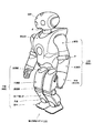
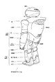
図1及び図2には、本発明の一実施形態に係る動作編集システムによる動作編集となる脚式移動ロボットの外観構成を示している。この脚式移動ロボットは、「人間形」又は「人間型」と呼ばれ、図示の通り、脚式移動ロボットは、胴体部と、頭部と、左右の上肢部と、脚式移動を行う左右2足の下肢部とで構成され、例えば胴体に内蔵されている制御部(図示しない)により機体の動作を統括的にコントロールするようになっている。 1 and 2 show an external configuration of a legged mobile robot that performs motion editing by the motion editing system according to an embodiment of the present invention. This legged mobile robot is called “humanoid” or “humanoid”, and as shown in the figure, the legged mobile robot has a torso, a head, left and right upper limbs, and a left and right that performs legged movement. It consists of two leg parts, for example, and controls the operation of the aircraft in an integrated manner by a control unit (not shown) built in the torso, for example.
左右各々の下肢は、大腿部と、膝関節と、脛部と、足首と、足平とで構成され、股関節によって体幹部の略最下端にて連結されている。また、左右各々の上肢は、上腕と、肘関節と、前腕とで構成され、肩関節によって体幹部の上方の左右各側縁にて連結されている。また、頭部は、首関節によって体幹部の略最上端中央に連結されている。 Each of the left and right lower limbs is composed of a thigh, a knee joint, a shin, an ankle, and a foot, and is connected by a hip joint at the substantially lower end of the trunk. The left and right upper limbs are composed of an upper arm, an elbow joint, and a forearm, and are connected to the left and right side edges above the trunk by shoulder joints. The head is connected to the substantially uppermost center of the trunk by a neck joint.
このように構成された脚式移動ロボットは、制御部による全身協調的な動作制御により、2足歩行を実現することができる。かかる2足歩行は、一般に、以下に示す各動作期間に分割される歩行周期を繰り返すことによって行なわれる。すなわち、 The legged mobile robot configured as described above can realize bipedal walking by whole body cooperative operation control by the control unit. Such biped walking is generally performed by repeating a walking cycle divided into the following operation periods. That is,
(1)右脚を持ち上げた、左脚による単脚支持期
(2)右足が接地した両脚支持期
(3)左脚を持ち上げた、右脚による単脚支持期
(4)左足が接地した両脚支持期
(1) Single leg support period with left leg lifted right leg (2) Both leg support period with right leg grounded (3) Single leg support period with right leg lifted with left leg (4) Both legs with left leg grounded Support period
この脚式移動ロボットの関節自由度は、アクチュエータ・モータを用いて実現され、各モータの回転位置、回転量などを取り出して、サーボ制御を行なうことにより、所望の動作パターンを再現するとともに、姿勢制御を行なうようになっている。すなわち、制御部(図示しない)は、各関節アクチュエータの駆動制御や各センサなどからの外部入力を処理するコントローラ(主制御部)や、電源回路その他の周辺機器類を搭載した筐体である。制御部は、その他、遠隔操作用の通信インターフェースや通信装置を含んでいてもよい。 The degree of freedom of joints of this legged mobile robot is realized by using actuators and motors. By taking out the rotation position and rotation amount of each motor and performing servo control, the desired movement pattern is reproduced and the posture Control is to be performed. In other words, the control unit (not shown) is a housing on which a controller (main control unit) that processes external inputs from each joint actuator, each sensor, and the like, a power supply circuit, and other peripheral devices are mounted. In addition, the control unit may include a communication interface and a communication device for remote operation.
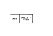
また、アクチュエータ・モータから高出力トルクを得るために、モータ部の出力端に減速部が配設されている(図3を参照のこと)。本実施形態では、減速部には遊星歯車機構が適用される。遊星歯車機構は、恒星としての太陽歯車と、惑星としての遊星歯車と、遊星歯車の公転軌道を規定する内歯歯車で構成される歯車構造であり、この他に、遊星歯車の軸中心をつなぐ遊星キャリアを備えている。遊星歯車機構を用いた減速機によれば、駆動軸と同軸上で減速をすることが可能なため、複段数の連結により強力な減速比を得ることができる。 Further, in order to obtain a high output torque from the actuator / motor, a speed reduction unit is provided at the output end of the motor unit (see FIG. 3). In this embodiment, a planetary gear mechanism is applied to the speed reduction unit. The planetary gear mechanism is a gear structure composed of a sun gear as a star, a planetary gear as a planet, and an internal gear that defines the revolution orbit of the planetary gear. In addition, the planetary gear mechanism connects the axis centers of the planetary gears. Has a planetary carrier. According to the speed reducer using the planetary gear mechanism, it is possible to reduce the speed on the same axis as the drive shaft, so that a strong reduction ratio can be obtained by connecting multiple stages.
ここで、アクチュエータのモータ部分と減速機部分が出力トルクに対し十分な捩り強度を持つためには、これらのケース若しくはハウジング類には十分な肉厚が必要となり、アクチュエータの取り付け側であるロボット本体の関節部フレームの肉厚やこれら部品間の隙間を考慮すると、ロボットの小型・軽量化の障害となる、という問題がある。すなわち、伝達するトルクに耐える強度を持つ厚みのある部品がフレーム側とアクチュエータ側にそれぞれ必要であるために小型・軽量化ができない。 Here, in order for the motor part and the speed reducer part of the actuator to have sufficient torsional strength with respect to the output torque, a sufficient thickness is required for these cases or housings, and the robot body on the actuator mounting side Considering the thickness of the joint frame and the gap between these parts, there is a problem that it becomes an obstacle to the reduction in size and weight of the robot. That is, since a thick part having strength that can withstand the torque to be transmitted is required on each of the frame side and the actuator side, the size and weight cannot be reduced.
これに対し、本実施形態では、ロボット本体の関節部フレームと減速機のケーシングを一体化して構成し、部品として共通化することにより、隙間を極小化して小型・軽量化、並びに高剛性化を図ることにした。 On the other hand, in this embodiment, the joint frame of the robot body and the casing of the speed reducer are integrated and configured as a component, thereby minimizing the gap and reducing the size, weight, and rigidity. I decided to plan.
上述したように、減速機に遊星歯車機構を用いた場合、この遊星減速機の内歯歯車のブローチ加工をフレームと一体化した状態で実現できるかがポイントとなる。何故ならば、ロボット本体のフレームは通常軽量化のためにマグネシウム合金で製造されるが、一般にマグネシウム合金にブローチ加工を行なうことができないからである。 As described above, when a planetary gear mechanism is used for the speed reducer, the point is whether the broaching of the internal gear of the planetary speed reducer can be realized in an integrated state with the frame. This is because the frame of the robot body is usually manufactured from a magnesium alloy for weight reduction, but generally broaching cannot be performed on the magnesium alloy.
遊星歯車の内歯は、通常、鉄系又はアルミニウム系の歯車形状の加工が容易な材質を用いられる。鉄は比重が高く装置の総重量の増大を招来することから、ロボット装置に組み込む場合には、アルミニウムを選択することが好ましいと本発明者らは思料する。 For the internal teeth of the planetary gear, a material that can be easily processed into an iron or aluminum gear shape is usually used. Since iron has a high specific gravity and causes an increase in the total weight of the apparatus, the present inventors consider that it is preferable to select aluminum when incorporated in a robot apparatus.
そこで、ロボット装置の各可動関節部位を、具体的には以下のように構成する。すなわち、 Therefore, each movable joint part of the robot apparatus is specifically configured as follows. That is,
(1)ロボットの可動関節部フレームは、軽量化のため、マグネシウム合金を使用する。これに対し、内歯歯車は、ブローチ加工性のため、アルミ材(例えば、A2017)のパイプ状の部品を、内歯スリーブとして、フレームとは別に製作する。これによって、マグネシウムによるロボット・フレームの超軽量化と、遊星減速機部分の内歯のアルミニウムによる軽量化とブローチ加工性を併せて実現することができる。 (1) The movable joint frame of the robot uses a magnesium alloy for weight reduction. On the other hand, the internal gear is manufactured separately from the frame by using a pipe-shaped part of an aluminum material (for example, A2017) as an internal tooth sleeve for broachability. As a result, it is possible to realize both the ultra-light weight of the robot frame by magnesium, the light weight by aluminum of the inner teeth of the planetary reduction gear and the broachability.
(2)温度環境下でマグネシウムとアルミニウムの伸び縮みの差が生じても、アクチュエータからフレームに伝達する過大なトルクに耐えられる保持力を持つ必要がある。そこで、アルミ製パイプ状の内歯スリーブを圧入、又は接着固定、熱バメ(ロボット・フレームを熱して内歯スリーブを大きな圧入代で固定)し、2部品を伝達トルクに対して十分に保持できる圧入力を生じさせる組立て方法を採用する。 (2) Even if a difference in expansion and contraction between magnesium and aluminum occurs in a temperature environment, it is necessary to have a holding force capable of withstanding an excessive torque transmitted from the actuator to the frame. Therefore, it is possible to hold the two parts sufficiently against the transmission torque by press-fitting or fixing aluminum pipe-shaped inner tooth sleeves and heat fixing (heating the robot frame and fixing the inner tooth sleeve with a large press-fitting allowance). An assembly method for generating pressure input is adopted.
(3)そして、このような関節部フレームと内歯スリーブの組み立て部材を構成した後、内歯スリーブ内径部を案内に使ってブローチ加工して、フレームと遊星減速機内歯を一体化して構成する。この結果、小型、軽量、高捩り剛性の可動関節を実現することができる。 (3) Then, after constructing an assembly member of such a joint part frame and an internal tooth sleeve, the internal tooth sleeve inner diameter part is used as a guide and broached, and the frame and the planetary reducer internal teeth are integrated. . As a result, a movable joint having a small size, light weight, and high torsional rigidity can be realized.
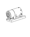
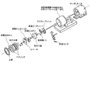
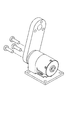
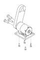
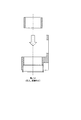
図4には、ロボット装置本体の関節部フレームと一体をなす減速部を備えた関節駆動用アクチュエータ装置の外観構成を示している。また、図5には、このアクチュエータ装置の分解図を示している。 FIG. 4 shows an external configuration of an actuator device for joint drive provided with a speed reduction unit integrated with the joint frame of the robot apparatus body. FIG. 5 is an exploded view of the actuator device.
図5に示すように、アクチュエータ装置は、駆動源としてのサーボ・モータの出力軸と同軸状に、遊星歯車機構からなる減速部が取り付けらける。この減速部のケーシングは、遊星減速機の内歯歯車とロボットの関節部フレームとを一体とした構造体であり、マグネシウム合金を型に鋳込むことで製作される。 As shown in FIG. 5, the actuator device can be attached with a speed reduction unit composed of a planetary gear mechanism coaxially with the output shaft of a servo motor as a drive source. The casing of this speed reduction part is a structure in which the internal gear of the planetary speed reducer and the joint frame of the robot are integrated, and is manufactured by casting a magnesium alloy into a mold.
また、遊星歯車機構は、図示の通り、スラスト・ワッシャー、遊星ピニオン(1)、遊星軸(1)、取付け板、太陽ピニオン、遊星ピニオン(2)、スペーサ、遊星軸(2)、一対のベアリングに挟まれた出力太陽、並びに上板が軸方向に配設され、マグネシウム合金からなる上記の減速部ケーシング内に収容されることにより構成される。 The planetary gear mechanism includes a thrust washer, a planetary pinion (1), a planetary shaft (1), a mounting plate, a solar pinion, a planetary pinion (2), a spacer, a planetary shaft (2), and a pair of bearings as shown in the figure. The output sun and the upper plate sandwiched between the two are arranged in the axial direction, and are housed in the speed reduction portion casing made of a magnesium alloy.
また、減速部のケーシング内部には、サーボ・モータの出力軸の原点を検出するための原点センサやその他の計測機器類も収容される。 In addition, an origin sensor for detecting the origin of the output shaft of the servo motor and other measuring devices are housed inside the casing of the deceleration unit.
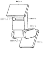
このような関節駆動用アクチュエータ装置は、図1並びに図2に示した脚式移動ロボットの各可動関節部位に適用することができる。図6には、この脚式移動ロボットの脚部の構造を取り出して示している。図示の脚部は、大腿部フレームと、脛部フレームと、足平フレームを備えている。 Such an actuator device for joint drive can be applied to each movable joint part of the legged mobile robot shown in FIG. 1 and FIG. FIG. 6 shows the leg structure of the legged mobile robot. The illustrated leg includes a thigh frame, a shin frame, and a foot frame.
胴体部に接続する腰部フレームの下面には、股関節(ピッチ軸)アクチュエータの出力を減速する減速機用のケーシングが一体的に構成されている。そして、減速機ケーシングの内周には内歯歯車が形設され、図6に示したように遊星歯車機構が内蔵されている。そして、股関節(ピッチ軸)アクチュエータの出力軸は大腿部フレームの上端部に取り付けられている。 A casing for a speed reducer that reduces the output of the hip joint (pitch axis) actuator is integrally formed on the lower surface of the waist frame connected to the body part. And the internal gear is formed in the inner periphery of the reduction gear casing, and the planetary gear mechanism is built in as shown in FIG. The output shaft of the hip joint (pitch axis) actuator is attached to the upper end of the thigh frame.
また、大腿部フレームの下端には、膝関節(ピッチ軸)アクチュエータの出力を減速する減速機用のケーシングが一体的に構成されている。そして、減速機ケーシングの内周には内歯歯車が形設され、図6に示したように遊星歯車機構が内蔵されている。そして、膝関節(ピッチ軸)アクチュエータの出力軸は脛部フレームの上端部に取り付けられている。 Further, a lower casing of the thigh frame is integrally configured with a speed reducer casing that decelerates the output of the knee joint (pitch axis) actuator. And the internal gear is formed in the inner periphery of the reduction gear casing, and the planetary gear mechanism is built in as shown in FIG. The output shaft of the knee joint (pitch axis) actuator is attached to the upper end of the shin frame.
また、足平フレームの上面には、足首関節(ピッチ軸)アクチュエータの出力を減速すると減速機用のケーシングが一体的に構成されている。そして、減速機ケーシングの内周には内歯歯車が形設され、図6に示したように遊星歯車機構が内蔵されている。そして、足首関節(ピッチ軸)アクチュエータの出力軸は脛部フレームの下端部に取り付けられている。 Further, a casing for a speed reducer is integrally formed on the upper surface of the foot frame when the output of the ankle joint (pitch axis) actuator is decelerated. And the internal gear is formed in the inner periphery of the reduction gear casing, and the planetary gear mechanism is built in as shown in FIG. The output shaft of the ankle joint (pitch axis) actuator is attached to the lower end of the shin frame.
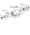
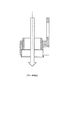
図7には、図4に示したアクチュエータ装置をロボットの脚部に適用した様子を示している。 FIG. 7 shows a state in which the actuator device shown in FIG. 4 is applied to the leg portion of the robot.
図示の通り、アクチュエータ装置のサーボ・モータの入力軸は、ベアリング及びストッパを介して一方の膝部フレームに螺着されている。 As shown in the figure, the input shaft of the servo motor of the actuator device is screwed to one knee frame via a bearing and a stopper.
また、アクチュエータ装置のサーボ・モータの出力軸に取り付けられた減速部の出力軸は、ワッシャーを介して他方の膝部フレームに螺着されている。 Further, the output shaft of the speed reduction portion attached to the output shaft of the servo motor of the actuator device is screwed to the other knee frame via a washer.
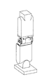
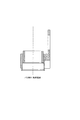
図8には、本実施形態に係るアクチュエータ装置をロボット装置の膝部に組み込んだ様子を示している。図示の通り、膝関節を構成する大腿部フレームの下端部において内歯歯車を形設し、ロボットの骨格に相当する大腿部フレームと遊星減速機を一体化することにより、この膝関節部を駆動するためのアクチュエータ・モータ部分と減速機部分が出力トルクに対し十分な捩り強度を持つことができる。 FIG. 8 shows a state in which the actuator device according to this embodiment is incorporated in the knee of the robot device. As shown in the figure, an internal gear is formed at the lower end of the thigh frame constituting the knee joint, and the thigh frame corresponding to the skeleton of the robot and the planetary reducer are integrated to form this knee joint. The actuator / motor part and the speed reducer part for driving the motor can have sufficient torsional strength against the output torque.
また、このようにロボット骨格と遊星減速機を一体化することにより強度の必要な構造部品を集約でき、無駄なスペースがなくなり、軽量且つコンパクトな関節機構ができる。これにより小型・軽量なロボット装置を実現することができる、という点を十分理解されたい。 In addition, by integrating the robot skeleton and the planetary speed reducer in this way, structural parts that require strength can be integrated, and there is no wasted space, and a lightweight and compact joint mechanism can be achieved. It should be fully understood that a small and lightweight robot apparatus can be realized.
また、図7並びに図8に示すような関節部構造によれば、駆動機構が回転軸の延長上に存在するので、ベルトドライブやギアトレインなどによって駆動力を回転軸に伝える方式と比べて減速機構、伝達機構の重量部品が回転軸中心に集まり、慣性モーメントが少ない可動関節機構が実現できる。これにより、歩行、ダンスなどのモーションが速い2足歩行エンターテイメント・ロボットを実現することができる。勿論、フレームと内歯の共通化などの部品共通化により大物構成部品を少なくできることから、材料費、組立て工数などのコストダウンが可能となる。 Further, according to the joint structure as shown in FIGS. 7 and 8, since the drive mechanism exists on the extension of the rotation shaft, the speed is reduced compared to a method in which the drive force is transmitted to the rotation shaft by a belt drive or a gear train. Since the heavy parts of the mechanism and transmission mechanism are gathered at the center of the rotation axis, a movable joint mechanism with a small moment of inertia can be realized. As a result, a bipedal walking entertainment robot with fast motion such as walking and dancing can be realized. Of course, since the large components can be reduced by sharing parts such as the common use of the frame and internal teeth, it is possible to reduce costs such as material costs and assembly man-hours.
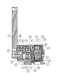
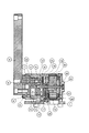
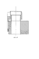
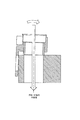
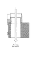
図9及び図10には、本発明の実施形態に係るロボット装置の関節部構造の斜視図と軸方向断面構成図をそれぞれ示している。既に述べたように、本実施形態においては、関節部フレームと減速機ケーシングが一体的に構成されている。また、図11及び図12には、これとの比較のため、従来の設計方式に基づいて関節部フレームと減速機ケーシングが別個の独立した部品として構成された場合の、関節部構造の斜視図と軸方向断面構成図をそれぞれ示している。 9 and 10 are respectively a perspective view and an axial sectional configuration diagram of the joint structure of the robot apparatus according to the embodiment of the present invention. As already described, in the present embodiment, the joint frame and the speed reducer casing are integrally formed. 11 and 12 are perspective views of the joint structure when the joint frame and the speed reducer casing are configured as separate and independent parts based on the conventional design method for comparison. FIG. 2 shows an axial sectional configuration diagram.
参照番号1は、ベースとなる関節部フレームであり、関節駆動用アクチュエータが取り付けられる。関節駆動用アクチュエータは、アクチュエータ・モータとその出力を減速する減速部で構成される。本実施形態では、減速部は、遊星歯車減速機により構成される。関節部フレーム1は、軽量化のため、マグネシウム合金の鋳造部品として構成される。
参照番号2は減速機ケーシングであり、その内周に沿って遊星歯車の公転軌道を規定する内歯歯車が形設されている。また、参照番号3はアクチュエータ・モータのケーシングである。
減速機ケーシング2、並びにアクチュエータ・モータのケーシング3には<タップ穴を持つ脚となる部分が2つずつ設けられている。図11並びに図12に示した従来の設計方式においては、これらのタップ穴はロボット装置側の関節部フレーム1への取り付けのために使われる。これに対し、本実施形態では、関節部フレーム1と減速機ケーシング2が一体的に構成されることから、これらのタップ穴が不要となる、というメリットがある。図11においては、減速機ケーシング2が図中下方から数本の螺子により関節部フレーム1に螺着されているが、図9では、これが不要である。
The
参照番号4は、関節駆動用アクチュエータが駆動する対象となる、ロボット装置の他方の関節部フレームである。関節部フレーム4は、対となる関節部フレーム1と同様に、軽量化のため、マグネシウム合金の鋳造部品として構成される。
参照番号5は、内歯スリーブであり、関節部フレームに対し、例えば圧入接着で固定され、アクチュエータからフレームに伝達する過大なトルクに耐えられる保持力が与えられている。この内歯スリーブ5の内径部分はブローチ加工により内歯が切られている。内歯スリーブ5は、軽量であるとともに加工容易性が求められ、本実施形態ではアルミ材質により構成される。
参照番号6は、アクチュエータの出力軸を回動可能に支持するための軸受けであり、その内輪を出力太陽7に圧入されている。
参照番号8は、軸受け6をアクチュエータの軸方向にて支持する上板である。本実施形態では、この上板8は可撓性を持つ板バネで構成されており、この板バネの弾性力若しくは復元力を利用して、軸受け6及び出力太陽7に予圧を印加し、出力太陽7に回転剛性を与える構成となっている。
参照番号9は、位置決めピンであり、出力太陽7に圧入され、出力太陽7と駆動対象部品(図示の例では関節フレーム4)との位相関係を規定する役目を持つ。
Reference numeral 9 is a positioning pin, which is press-fitted into the output sun 7 and has a role of defining the phase relationship between the output sun 7 and the component to be driven (
参照番号10は、出力段側遊星軸である。図示の例では、出力太陽7に対し、3本の出力段側遊星軸10が円周上で均等に配置され、圧入されている、
参照番号11は、出力段側遊星ピニオンであり、その表面をグリース(潤滑油)で十分に潤滑されてから、出力段側遊星軸10に取り付けられる。
参照番号12は、太陽ピニオンであり、取り付け板13により圧入されている。
参照番号14は、入力段側遊星軸である。図示の例では、3本の入力段側遊星軸14が円周上で均等に配置され、圧入されている、
参照番号15は、入力段側遊星ピニオンであり、その表面をグリース(潤滑油)で十分に潤滑されてから、入力段側遊星軸14に取り付けられる。
ここで、キャリア・プレート上の3本の入力段遊星軸14と太陽ピニオン12の間の平行度並びに同芯度を十分に高い精度(例えば50μm以下)に抑えることが、遊星ピニオン11、15や内歯の摩滅を防ぐ上で必要になる。
Here, to suppress the parallelism and concentricity between the three input stage
参照番号16は入力ピニオン、参照番号17は、アクチュエータ・モータ側のケーシング3と入力段側遊星ピニオン15の間の摩擦を減らすために挿設された胴ワッシャーである。また、参照番号18はアクチュエータ・モータのケーシング3用のベアリングであり、参照番号19はアクチュエータ・モータの固定子巻き線組み立て部品である。これらをアクチュエータ・モータ側のケーシング3内に圧入接着により固定された上で、駆動用のコイル巻き線の振動を抑制するために、粘度の高い接着剤により含浸固定される。
参照番号20は、アクチュエータ・モータの回転子マグネット組み立て部品であり、段付き軸とマグネットを接着固定した後に、マグネットを着磁磁化して使用する。
参照番号21は、駆動基板であり、回転子マグネットへの駆動電流(モータ電流)を制御する。
参照番号22は、側板であり、アクチュエータ・モータのケーシング3内部にすべての部品を組み込んだ後に内部を隠蔽する(蓋をする)ために用いられる。
参照番号23は、ボール・ベアリングであり、回転子マグネット20を回転可能に軸支する。
参照番号24は、通信基板であり、外部システムとの通信と、回転センサ基板25から出力される回転子マグネット20の回転状態の情報を受信し、駆動基板21への信号や電源の供給を行なう。
回転センサ基板25は、回転子マグネット20の端面に取り付けられたマグネットの磁気を感知するセンサ(ホール素子)を搭載している。
The
参照番号26は、回転子マグネット20の回転位相の原点を感知する原点センサである。
Reference numeral 26 is an origin sensor that senses the origin of the rotational phase of the
続いて、減速機ケーシング2に内歯スリーブ5を取り付けて内歯歯車を形設することにより、ベース側の関節部フレーム1と減速機ケーシング2を一体化するための製作手順について説明する。
Next, a manufacturing procedure for integrating the base-side
関節部フレーム1は、その比強度の高さからマグネシウム合金(例えばAZ91D)が用いられる。但し、マグネシウム合金に直接ブローチ加工をして内歯を生成することができない。代替の工程について、図13〜図18を参照しながら説明する。
The
(1)まず、パイ部状の部品からなる内歯スリーブを製作する。内歯スリーブ5には、加工性の良さからアルミニウム(例えばA2017)が用いられ、ブローチ加工によりその内周に内歯歯車が形設される。
(1) First, an internal tooth sleeve made of a pie-shaped part is manufactured. Aluminum (for example, A2017) is used for the
(2)次いで、ロボットの関節部フレーム1(マグネシウム合金)に内歯スリーブ5(A2017)を圧入又は接着固定、熱バメ(ロボットの関節部フレーム1を熱して内歯スリーブを大きな圧入代で固定)する(図13を参照のこと)。
(2) Next, the inner sleeve 5 (A2017) is press-fitted or bonded and fixed to the joint frame 1 (magnesium alloy) of the robot, and the thermal sleeve (the robot's
このような内歯スリーブ5の取り付け方法により、ロボットの関節部装置として完成し、通常の装置駆動により想定されるさまざまな温度環境下でマグネシウムとアルミニウムの伸び縮みの差が生じても、マグネシウム合金からなる関節部フレームとアルミニウムからなる内歯歯車が熱膨張率の相違により分離することなく、アクチュエータからフレームに伝達する過大なトルクに耐えられる保持力を得ることができる。
With such an
ここで、外径φ25〜30mmのパイプ材を製品使用温度環境下で十分な保持力を与えるだけの圧入代で圧入するためには数百キロの圧入力が必要になる。そこで、事前にロボットの関節部フレーム1のマグネシウム合金を加熱して熱膨張させ、その内径を内歯スリーブ5の外径よりも大きくした状態を形成した後、瞬間的に隙間バメする根ツバメの方が良好な圧入が可能なので好ましい。圧入の良し悪しがブローチ加工や遊星ギアの出来具合に影響するので、安定した圧入作業が要求される。
Here, in order to press-fit a pipe material having an outer diameter of φ25 to 30 mm with a press-fitting allowance sufficient to give a sufficient holding force under a product use temperature environment, press input of several hundred kilometers is required. Therefore, after the magnesium alloy of the
(3)次いで、内歯スリーブ5とロボット側の関節部フレーム1の内歯スリーブ内径部を案内に使って、内歯スリーブのパイプの内周にブローチ加工を施し、内歯歯車を形設する(図14を参照のこと)。
(3) Next, using the
このとき、関節部フレームをセッティングする際(図16を参照のこと)、内歯スリーブ5とロボット側の関節部フレーム1単体で立てるには形状的なバランスがよくないので(図17を参照のこと)、冶具に内歯スリーブ内径部が加工する円筒の端面を全周均等に受けて直角に立つような工夫することが必要になる(図18を参照のこと)。
At this time, when setting the joint frame (see FIG. 16), the shape balance is not good to stand by the
図17に示したように、安定したセッティングが出来ないと、ブローチ加工中の切削抵抗によってサンプルが傾き、内歯が曲がってあけられてしまう。すると内部に組みつけられる遊星ピニオンとの接触若しくは隙間関係が設計通りにならない。最悪の場合、部品を組み付けるためのすきますら確保できず、組み立て不能となってしまう。また、接触若しくは隙間関係が設計通りでないと、設計目標のバックラッシュ、バックドライブを実現できなかったり、減速機運転中に短時間で歯が摩滅してしまったりすることになる。 As shown in FIG. 17, if a stable setting cannot be made, the sample is inclined due to the cutting resistance during broaching, and the inner teeth are bent and opened. Then, the contact or clearance relationship with the planetary pinion assembled inside does not become as designed. In the worst case, even the clearance for assembling the parts cannot be secured, and the assembly becomes impossible. Also, if the contact or clearance relationship is not as designed, the design target backlash and backdrive cannot be realized, or teeth are worn out in a short time during the operation of the reduction gear.
(4)最後に、バリ取りを行ない、組み上がった状態で洗浄する(図15を参照のこと)。以上の工程により、減速機ケーシング2と一体化した関節部フレーム1が完成する。
(4) Finally, deburring is performed and cleaning is performed in an assembled state (see FIG. 15). The
本明細書では、特定の実施形態を参照しながら、本発明について詳解してきた。しかしながら、本発明の要旨を逸脱しない範囲で当業者が該実施形態の修正や代用を成し得ることは自明である。 In the present specification, the present invention has been described in detail with reference to specific embodiments. However, it is obvious that those skilled in the art can make modifications and substitutions of the embodiment without departing from the gist of the present invention.
本発明の要旨は、必ずしも「ロボット」と称される製品には限定されない。すなわち、電気的若しくは磁気的な作用を用いて人間の動作に似せた運動を行なう機械装置あるいはその他一般的な移動体装置であるならば、例えば玩具などのような他の産業分野に属する製品であっても、同様に本発明を適用することができる。 The gist of the present invention is not necessarily limited to a product called a “robot”. That is, if it is a mechanical device or other general mobile device that performs a movement resembling human movement using electrical or magnetic action, it is a product belonging to another industrial field such as a toy. Even if it exists, this invention can be applied similarly.
要するに、例示という形態で本発明を開示してきたのであり、本明細書の記載内容を限定的に解釈するべきではない。本発明の要旨を判断するためには、冒頭に記載した特許請求の範囲の欄を参酌すべきである。 In short, the present invention has been disclosed in the form of exemplification, and the description of the present specification should not be interpreted in a limited manner. In order to determine the gist of the present invention, the claims section described at the beginning should be considered.
1…関節部フレーム(ベース)
2…減速機ケーシング
3…アクチュエータ・モータのケーシング
4…関節部フレーム(駆動対象部品)
5…内歯スリーブ
6…軸受け
7…出力太陽
8…上板(板バネ)
9…位置決めピン
10…出力段側遊星軸
11…出力段側遊星ピニオン
12…太陽ピニオン
13…取り付け板
14…入力段側遊星軸
15…入力段側遊星ピニオン
16…入力ピニオン
17…胴ワッシャー
18…ベアリング
19…固定子コア巻き線組み立て部品
20…回転子マグネット組み立て部品
21…駆動基板
22…側板
23…ボール・ベアリング
24…通信基盤
25…回転センサ基板
26…原点センサ
1 ... Joint frame (base)
2.
5 ...
DESCRIPTION OF SYMBOLS 9 ... Positioning
Claims (12)
関節を駆動するアクチュエータのモータ部と、
前記モータ部の出力端に配設された減速部と、
前記減速部のケーシングと一体的に構成された関節部フレームと、
を具備することを特徴とするロボット装置。 In a robot apparatus having a plurality of joints,
A motor part of an actuator that drives the joint;
A speed reduction portion disposed at an output end of the motor portion;
A joint part frame configured integrally with the casing of the speed reduction part;
A robot apparatus comprising:
ことを特徴とする請求項1に記載のロボット装置。 The speed reduction unit is configured by a planetary gear mechanism including a sun gear as a star, a planetary gear as a planet, and an internal gear that defines the revolution orbit of the planetary gear.
The robot apparatus according to claim 1.
ことを特徴とする請求項2に記載のロボット装置。 The joint frame includes a joint frame body having a mounting portion of the motor unit, and an internal gear portion of the planetary gear mechanism.
The robot apparatus according to claim 2.
前記内歯歯車部は、前記内歯収容部に収容された内歯スリーブ内径部を案内に使ってブローチ加工を施して形設される、
ことを特徴とする請求項3に記載のロボット装置。 The joint part frame includes an internal tooth accommodating part for accommodating an internal tooth sleeve made of a pipe-shaped part,
The internal gear portion is formed by performing broaching using the inner sleeve inner diameter portion accommodated in the inner tooth accommodating portion as a guide,
The robot apparatus according to claim 3.
ことを特徴とする請求項3に記載のロボット装置。 The inner tooth sleeve is press-fitted, or adhesively fixed, and attached to the inner tooth receiving portion of the joint frame by heat shrinkage,
The robot apparatus according to claim 3.
ことを特徴とする請求項3に記載のロボット装置。 The joint frame is made of a magnesium alloy, and the internal tooth sleeve is made of an aluminum-based material.
The robot apparatus according to claim 3.
関節を駆動するアクチュエータのモータ部と、
前記モータ部の出力端に配設された減速部と、
前記ロボットの関節部フレームと一体的に構成された前記減速部のケーシングと、
を具備することを特徴とするロボットのための関節装置。 In the joint device that constitutes the joint freedom of the robot,
A motor part of an actuator that drives the joint;
A speed reduction portion disposed at an output end of the motor portion;
A casing of the speed reducer configured integrally with the joint frame of the robot;
A joint device for a robot, comprising:
ことを特徴とする請求項7に記載のロボットのための関節装置。 The speed reduction unit is configured by a planetary gear mechanism including a sun gear as a star, a planetary gear as a planet, and an internal gear that defines the revolution orbit of the planetary gear.
The joint device for a robot according to claim 7.
ことを特徴とする請求項8に記載のロボットのための関節装置。 The casing of the speed reduction part includes an attachment part of the motor part and an internal gear part of the planetary gear mechanism.
The joint device for a robot according to claim 8.
前記内歯歯車部は、前記内歯収容部に収容された内歯スリーブ内径部を案内に使ってブローチ加工を施して形設される、
ことを特徴とする請求項9に記載のロボットのための関節装置。 The casing of the speed reduction part includes an internal tooth receiving part for receiving an internal tooth sleeve made of a pipe-shaped part,
The internal gear part is formed by performing broaching using the inner sleeve inner diameter part accommodated in the internal tooth accommodating part as a guide,
The joint device for a robot according to claim 9.
ことを特徴とする請求項9に記載のロボットのための関節装置。 The inner tooth sleeve is press-fitted or bonded and fixed, and attached to the inner tooth accommodating portion of the casing of the speed reduction portion by heat shrinkage,
The joint device for a robot according to claim 9.
ことを特徴とする請求項9に記載のロボットのための関節装置。
The casing of the speed reduction part is made of a magnesium alloy, and the inner sleeve is made of an aluminum-based material.
The joint device for a robot according to claim 9.
Priority Applications (1)
| Application Number | Priority Date | Filing Date | Title |
|---|---|---|---|
| JP2004112596A JP2005297079A (en) | 2004-04-06 | 2004-04-06 | Robot device and robot joint device |
Applications Claiming Priority (1)
| Application Number | Priority Date | Filing Date | Title |
|---|---|---|---|
| JP2004112596A JP2005297079A (en) | 2004-04-06 | 2004-04-06 | Robot device and robot joint device |
Publications (1)
| Publication Number | Publication Date |
|---|---|
| JP2005297079A true JP2005297079A (en) | 2005-10-27 |
Family
ID=35329250
Family Applications (1)
| Application Number | Title | Priority Date | Filing Date |
|---|---|---|---|
| JP2004112596A Pending JP2005297079A (en) | 2004-04-06 | 2004-04-06 | Robot device and robot joint device |
Country Status (1)
| Country | Link |
|---|---|
| JP (1) | JP2005297079A (en) |
Cited By (4)
| Publication number | Priority date | Publication date | Assignee | Title |
|---|---|---|---|---|
| WO2015151842A1 (en) * | 2014-04-03 | 2015-10-08 | ナブテスコ株式会社 | Humanoid robot joint mechanism |
| WO2015151843A1 (en) * | 2014-04-03 | 2015-10-08 | ナブテスコ株式会社 | Joint mechanism for humanoid robot |
| CN111355331A (en) * | 2018-12-21 | 2020-06-30 | 日本电产株式会社 | Actuator |
| WO2024140199A1 (en) * | 2022-12-30 | 2024-07-04 | 北京石头世纪科技股份有限公司 | Mechanical joint, mechanical arm, and self-moving cleaning device |
-
2004
- 2004-04-06 JP JP2004112596A patent/JP2005297079A/en active Pending
Cited By (8)
| Publication number | Priority date | Publication date | Assignee | Title |
|---|---|---|---|---|
| WO2015151842A1 (en) * | 2014-04-03 | 2015-10-08 | ナブテスコ株式会社 | Humanoid robot joint mechanism |
| WO2015151843A1 (en) * | 2014-04-03 | 2015-10-08 | ナブテスコ株式会社 | Joint mechanism for humanoid robot |
| JP2015196238A (en) * | 2014-04-03 | 2015-11-09 | ナブテスコ株式会社 | Humanoid robot joint mechanism |
| JP2015196237A (en) * | 2014-04-03 | 2015-11-09 | ナブテスコ株式会社 | Humanoid robot joint mechanism |
| CN111355331A (en) * | 2018-12-21 | 2020-06-30 | 日本电产株式会社 | Actuator |
| JP2020102939A (en) * | 2018-12-21 | 2020-07-02 | 日本電産株式会社 | Actuator |
| CN111355331B (en) * | 2018-12-21 | 2022-10-21 | 日本电产株式会社 | Actuator |
| WO2024140199A1 (en) * | 2022-12-30 | 2024-07-04 | 北京石头世纪科技股份有限公司 | Mechanical joint, mechanical arm, and self-moving cleaning device |
Similar Documents
| Publication | Publication Date | Title |
|---|---|---|
| JP7288926B2 (en) | Screw actuators for legged robots | |
| JP6859434B2 (en) | Transmission with integrated overload protection for legged robots | |
| US9879760B2 (en) | Rotary actuator with shortest force path configuration | |
| KR0178812B1 (en) | Industrial robot with combined accelerator gear unit | |
| JP2021182862A (en) | Integrated motor and controller for legged robots | |
| JP5528207B2 (en) | Link actuator | |
| US5355743A (en) | Robot and robot actuator module therefor | |
| JP2006507464A (en) | Standardized rotary actuator | |
| EP2532927B1 (en) | Modular rotational electric actuator | |
| WO2020078158A1 (en) | Robot dual-joint unit as well as legged robot and cooperative robot arm using same | |
| US12564940B2 (en) | Screw actuator | |
| CN101112760A (en) | Space Manipulator Modular Joints | |
| US20240217096A1 (en) | Robotic Joint Actuator | |
| CN106132641A (en) | The articulation mechanism of humanoid robot | |
| CN114800602A (en) | Compact variable-rigidity joint module with flexible element | |
| CN112405606B (en) | Five-degree-of-freedom time-sharing driving power-assisted mechanical arm with mechanical locking function | |
| JP2005297079A (en) | Robot device and robot joint device | |
| CN112104149A (en) | Modular joint of biped robot | |
| JP2005297081A (en) | Robot device and robot joint device | |
| JP2005297080A (en) | Robot device and robot joint device | |
| CN112659175B (en) | Joint with streamline shell envelope | |
| CN213566217U (en) | Joint drive mechanism and robot | |
| CN121468652B (en) | Multi-mode robot elbow joint mechanism | |
| CN114952926A (en) | A compact integrated double-joint module | |
| CN224144687U (en) | Joint structure and robot |