JP2005297061A - Molding device - Google Patents
Molding device Download PDFInfo
- Publication number
- JP2005297061A JP2005297061A JP2005055057A JP2005055057A JP2005297061A JP 2005297061 A JP2005297061 A JP 2005297061A JP 2005055057 A JP2005055057 A JP 2005055057A JP 2005055057 A JP2005055057 A JP 2005055057A JP 2005297061 A JP2005297061 A JP 2005297061A
- Authority
- JP
- Japan
- Prior art keywords
- pressure
- chamber
- mold
- piston
- molding
- Prior art date
- Legal status (The legal status is an assumption and is not a legal conclusion. Google has not performed a legal analysis and makes no representation as to the accuracy of the status listed.)
- Granted
Links
Images

Classifications
-
- B—PERFORMING OPERATIONS; TRANSPORTING
- B22—CASTING; POWDER METALLURGY
- B22D—CASTING OF METALS; CASTING OF OTHER SUBSTANCES BY THE SAME PROCESSES OR DEVICES
- B22D17/00—Pressure die casting or injection die casting, i.e. casting in which the metal is forced into a mould under high pressure
- B22D17/20—Accessories: Details
- B22D17/2015—Means for forcing the molten metal into the die
- B22D17/2069—Exerting after-pressure on the moulding material
-
- B—PERFORMING OPERATIONS; TRANSPORTING
- B22—CASTING; POWDER METALLURGY
- B22D—CASTING OF METALS; CASTING OF OTHER SUBSTANCES BY THE SAME PROCESSES OR DEVICES
- B22D17/00—Pressure die casting or injection die casting, i.e. casting in which the metal is forced into a mould under high pressure
- B22D17/08—Cold chamber machines, i.e. with unheated press chamber into which molten metal is ladled
- B22D17/12—Cold chamber machines, i.e. with unheated press chamber into which molten metal is ladled with vertical press motion
-
- B—PERFORMING OPERATIONS; TRANSPORTING
- B22—CASTING; POWDER METALLURGY
- B22D—CASTING OF METALS; CASTING OF OTHER SUBSTANCES BY THE SAME PROCESSES OR DEVICES
- B22D17/00—Pressure die casting or injection die casting, i.e. casting in which the metal is forced into a mould under high pressure
- B22D17/20—Accessories: Details
- B22D17/2015—Means for forcing the molten metal into the die
- B22D17/2023—Nozzles or shot sleeves
-
- B—PERFORMING OPERATIONS; TRANSPORTING
- B22—CASTING; POWDER METALLURGY
- B22D—CASTING OF METALS; CASTING OF OTHER SUBSTANCES BY THE SAME PROCESSES OR DEVICES
- B22D17/00—Pressure die casting or injection die casting, i.e. casting in which the metal is forced into a mould under high pressure
- B22D17/20—Accessories: Details
- B22D17/2015—Means for forcing the molten metal into the die
- B22D17/203—Injection pistons
-
- B—PERFORMING OPERATIONS; TRANSPORTING
- B22—CASTING; POWDER METALLURGY
- B22D—CASTING OF METALS; CASTING OF OTHER SUBSTANCES BY THE SAME PROCESSES OR DEVICES
- B22D21/00—Casting non-ferrous metals or metallic compounds so far as their metallurgical properties are of importance for the casting procedure; Selection of compositions therefor
- B22D21/02—Casting exceedingly oxidisable non-ferrous metals, e.g. in inert atmosphere
- B22D21/04—Casting aluminium or magnesium
Landscapes
- Engineering & Computer Science (AREA)
- Mechanical Engineering (AREA)
- Moulds For Moulding Plastics Or The Like (AREA)
- Molds, Cores, And Manufacturing Methods Thereof (AREA)
- Injection Moulding Of Plastics Or The Like (AREA)
Abstract
【課題】製品の成型作業の能率を向上することができるとともに、貯留室内に余剰の溶湯が注入されても、成型作業を適正に行うことができる成型装置を提供する。
【解決手段】下型37に溶湯Yの貯留室47を設ける。下型37の第1成型面371と上型54の第2成型面541とによりキャビティKを形成する。キャビティKに面して上型54の第2成型面541にダンパー室Rを形成する。このダンパー室Rにシリンダ74によって往復動される加圧ロッド77を進入する。押出ロッド40によって貯留室47内の溶湯YがキャビティK内に押し出されたとき、余剰の溶湯Yをダンパー室Rに進入させ、成型作業の最終段階で余剰の溶湯Yを加圧ロッド77によって加圧する。
【選択図】 図1Provided is a molding apparatus capable of improving the efficiency of a product molding operation and appropriately performing the molding operation even when an excess molten metal is injected into a storage chamber.
A lower mold 37 is provided with a storage chamber 47 for molten metal Y. A cavity K is formed by the first molding surface 371 of the lower mold 37 and the second molding surface 541 of the upper mold 54. A damper chamber R is formed on the second molding surface 541 of the upper mold 54 so as to face the cavity K. A pressure rod 77 reciprocated by a cylinder 74 enters the damper chamber R. When the molten metal Y in the storage chamber 47 is pushed out into the cavity K by the extrusion rod 40, the excessive molten metal Y enters the damper chamber R, and the excessive molten metal Y is added by the pressure rod 77 at the final stage of the molding operation. Press.
[Selection] Figure 1
Description
本発明は、各種の製品をキャビティ内で成型するための成型装置に関するものである。 The present invention relates to a molding apparatus for molding various products in a cavity.
従来の成型装置として、図12に示すものが提案されている。この成型装置はベッド111に固定された金型把持体112に対し取り外し可能に装着された固定金型113と、前記金型把持体112に対し上下一対の案内レール114に沿って前後方向(図12の左右)の往復動可能に装着された金型把持体115とを備えている。この金型把持体115に可動金型116が取り外し可能に装着されている。又、前記ベッド111の右側方には型閉めされた固定金型113と可動金型116によって形成されるキャビティ内にアルミニウム等の溶湯を流し込んで製品を成型するための射出機構117が装着されている。この射出機構117は前記金型把持体112を貫通して固定金型113に連通された溶湯の貯留室119を有するスリーブ118を備えている。このスリーブ118の外端部には溶湯の注入口120が設けられている。前記貯留室119の内部には射出ロッド121が挿入され、シリンダ122によって往復動されるようになっている。
As a conventional molding apparatus, one shown in FIG. 12 has been proposed. This molding apparatus includes a fixed
ところが、上記従来の成型装置は、固定金型113に対し可動金型116を型閉めした状態で、注入口120から溶湯を貯留室119内に注入し、その後、シリンダ122を作動して射出ロッド121を前進させる。そして、貯留室119内の溶湯をキャビティ内に圧入する必要があるため、成型作業の工程数が型閉め・溶湯注入・溶湯圧入の三行程と多くなり、成型作業の能率が低下し製造コストの低減を図ることができないという問題があった。
However, the conventional molding apparatus injects the molten metal into the
又、上記従来の成型装置は、型閉めした後にキャビティ内の圧力を減圧することにより射出成型時にキャビティ内の空気が溶湯に混入しないようにしている。しかしながら、この減圧動作を高い負圧力で行うと、射出ロッド121の外周面とスリーブ118の内周面との細隙のシールが確保できないので、外部の空気がシール不足の細隙から貯留室119内の上部に侵入する。この空気がキャビティ側に引き込まれ、この過程で溶湯に微細な空気の気泡が混入し、製品の品質を低下するという問題があった。従来の減圧機構では前記負圧力を大きくすることが難しいので、製品の品質を向上する上で限界があった。
The conventional molding apparatus reduces the pressure in the cavity after closing the mold so that the air in the cavity does not enter the molten metal during injection molding. However, if this decompression operation is performed at a high negative pressure, the seal between the outer peripheral surface of the
本願発明者は上記問題を解決するため新しいタイプの成型装置を提案した。この成型装置は、成型用のキャビティを形成可能な第1型ユニットと、第2型ユニットを接近又は離間可能に対向して配置し、前記第1型ユニットと第2型ユニットの少なくとも一方の型ユニットの内部に成型用のキャビティに連通する被成型材料の貯留室を設けている。又、この成型装置は、前記貯留室を有する型ユニットに対応して前記両型ユニットの型閉め動作の後に前記貯留室内の被成型材料をキャビティ内に押し出す押出手段を設けている。 The inventor of the present application has proposed a new type of molding apparatus to solve the above problems. In this molding apparatus, a first mold unit capable of forming a molding cavity and a second mold unit are arranged to face each other so that they can approach or separate from each other, and at least one of the first mold unit and the second mold unit is disposed. A storage chamber for a molding material that communicates with a molding cavity is provided inside the unit. Further, this molding apparatus is provided with an extrusion means for extruding the molding material in the storage chamber into the cavity after the mold closing operation of both mold units corresponding to the mold unit having the storage chamber.
ところが、上記成型装置は、貯留室に貯留された溶湯が多過ぎる場合には、余剰の溶湯が型ユニットの型合わせ面から外部に漏出して、製品の外形形状を損なうという問題が生じた。このため、貯留室に貯留する溶湯の量を最初に厳密に計量しなければならず、成型作業の能率を低下させるという問題が生じた。 However, when the molten metal stored in the storage chamber is too much, the molding apparatus has a problem that the excessive molten metal leaks outside from the mold mating surface of the mold unit, and the outer shape of the product is damaged. For this reason, the amount of the molten metal stored in the storage chamber has to be strictly measured first, which causes a problem of reducing the efficiency of the molding operation.
本発明の目的は、上記従来の技術に存する問題点を解消して、製品の成型作業の能率を向上することができるとともに、貯留室内に余剰の溶湯が注入されても、成型作業を適正に行うことができる成型装置を提供することにある。 The object of the present invention is to solve the above-mentioned problems in the prior art and to improve the efficiency of product molding work, and to properly perform molding work even if excess molten metal is injected into the storage chamber. An object of the present invention is to provide a molding apparatus that can be used.
上記問題点を解決するために、請求項1に記載の発明は、成型用のキャビティを形成可能な第1型ユニットと第2型ユニットを接近又は離間可能に対向して配置し、前記両型ユニットの少なくとも一方の型ユニットの内部に前記キャビティに連通する被成型材料の貯留室を設け、該貯留室を有する型ユニットに対応して前記両型ユニットの型閉め動作の後に前記貯留室内の被成型材料をキャビティ内に押し出す押出手段を設け、前記型ユニットに対し前記キャビティ内の余剰被成型材料を収容するダンパー室を設けるとともに、余剰被成型材料を加圧する加圧手段を設けたことを要旨とする。
In order to solve the above-mentioned problems, the invention according to
請求項2に記載の発明は、請求項1において、前記加圧手段は、流体圧シリンダであって、そのピストンロッドにより往復動される加圧部材がダンパー室に収容されていることを要旨とする。
The invention of claim 2 is summarized in that, in
請求項3に記載の発明は、請求項1又は2において、前記加圧手段の加圧部材は、前記押出手段による被成型材料の押し出し動作の開始時に前記ダンパー室の容積を最小にする位置に保持され、前記貯留室の被成型材料のキャビティへの押し出し動作の最終段階で容積が最大となる位置に切り換えられるように構成されていることを要旨とする。 According to a third aspect of the present invention, in the first or second aspect, the pressurizing member of the pressurizing unit is at a position where the volume of the damper chamber is minimized at the start of the extrusion operation of the molding material by the extruding unit. The gist of the present invention is that it is configured to be held and switched to a position where the volume is maximized in the final stage of the pushing operation of the molding material in the storage chamber to the cavity.
請求項4に記載の発明は、請求項1又は2において、前記加圧手段の加圧部材は、前記押出手段による被成型材料の押し出し動作の開始時に前記ダンパー室の容積を最大にする位置に保持され、貯留室の被成型材料のキャビティへの押し出し動作の最終段階で容積が最小となる位置に切り換えられるように構成されていることを要旨とする。 According to a fourth aspect of the present invention, in the first or second aspect, the pressurizing member of the pressurizing unit is at a position where the volume of the damper chamber is maximized at the start of the extrusion operation of the molding material by the extruding unit. The gist is that it is configured to be held and switched to a position where the volume is minimized in the final stage of the pushing operation of the molding material in the storage chamber to the cavity.
請求項5に記載の発明は、請求項4において、前記貯留室の被成型材料のキャビティへの押し出し動作が終了した後に加圧部材により低圧力で前記ダンパー室の余剰溶湯を加圧し、次に、高圧力で余剰溶湯を加圧するように構成されていることを要旨とする。 According to a fifth aspect of the present invention, in the fourth aspect, after the operation of pushing the molding material in the storage chamber into the cavity is finished, the excess molten metal in the damper chamber is pressurized with a pressure member at a low pressure, and then The gist is that it is configured to pressurize the excess molten metal at a high pressure.
請求項6に記載の発明は、請求項2〜5のいずれか一項において、前記流体圧シリンダのピストン側シリンダ室とロッド側シリンダ室には圧力流体供給源から流体が第1管路、第2管路及び両管路に設けた第1電磁切換弁を介して交互に供給されるようになっており、前記ピストン側シリンダ室に接続された第1管路には第1圧力調整弁が設けられ、前記ピストン側シリンダ室が第1電磁切換弁によってドレンポートに切り換えられた状態で、制御装置からの信号によって前記第1圧力調整弁を制御して前記ピストン側シリンダ室内の流体の圧力を設定圧力に制御するように構成されていることを要旨とする。 According to a sixth aspect of the present invention, in any one of the second to fifth aspects, the fluid from the pressure fluid supply source is supplied to the piston side cylinder chamber and the rod side cylinder chamber of the fluid pressure cylinder. The first pressure switching valve is alternately supplied via the first electromagnetic switching valves provided in the two pipe lines and the two pipe lines, and a first pressure adjusting valve is provided in the first pipe line connected to the piston side cylinder chamber. In the state where the piston side cylinder chamber is switched to the drain port by the first electromagnetic switching valve, the pressure of the fluid in the piston side cylinder chamber is controlled by controlling the first pressure adjusting valve by a signal from the control device. The gist is that it is configured to control to the set pressure.
請求項7に記載の発明は、請求項1〜6のいずれか一項において、第1型ユニットとしての下型ユニットの上方に第2型ユニットとしての上型ユニットが装設され、前記押出手段は、前記貯留室を形成した下型ユニットに対し、該貯留室の底部から該貯留室に進退可能に挿入された押出ロッドにより構成されていることを要旨とする。
The invention according to claim 7 is the extrusion means according to any one of
請求項8に記載の発明は、請求項7において、前記貯留室には前記ダンパー室の機能が付与され、下型ユニットの下部には、前記押出ロッドを作動する流体圧シリンダが配設され、該流体圧シリンダのピストン側シリンダ室とロッド側シリンダ室には圧力流体供給源から流体が第1管路、第2管路及び両管路に設けた第1電磁切換弁を介して交互に供給されるようになっており、前記ピストン側シリンダ室に接続された第1管路には第1圧力調整弁が設けられ、前記ピストン側シリンダ室が第1電磁切換弁によってドレンポートに切り換えられた状態で、制御装置からの信号によって前記第1圧力調整弁を制御して前記ピストン側シリンダ室内の流体の圧力を設定圧力に制御するように構成されていることを要旨とする。 According to an eighth aspect of the present invention, in the seventh aspect, the function of the damper chamber is imparted to the storage chamber, and a fluid pressure cylinder that operates the push rod is disposed below the lower mold unit. Fluid is alternately supplied from the pressure fluid supply source to the piston-side cylinder chamber and the rod-side cylinder chamber of the fluid pressure cylinder via the first electromagnetic switching valve provided in the first pipeline, the second pipeline, and both pipelines. The first pipe connected to the piston-side cylinder chamber is provided with a first pressure regulating valve, and the piston-side cylinder chamber is switched to the drain port by the first electromagnetic switching valve. The gist of the invention is that the first pressure regulating valve is controlled by a signal from the control device to control the fluid pressure in the piston-side cylinder chamber to a set pressure.
請求項9に記載の発明は、請求項8において、前記圧力流体供給源と流体圧シリンダのピストン側シリンダ室との間には、第3管路及び第4管路が並列に接続され、前記第3管路には第2圧力調整弁、第2電磁切換弁、増速シリンダ及び第1逆止弁が直列に接続され、前記第4管路には、第3圧力調整弁、第3電磁切換弁及び第2逆止弁が直列に接続され、前記第2電磁切換弁は、前記両型ユニットの型閉め工程初期において前記制御装置からの信号によってドレンポートから供給ポートに切り換えられて、ピストン側シリンダ室を加圧し、前記第3電磁切換弁は、制御装置からの信号によって、貯留室の被成型材料のキャビティへの押し出し動作の最終段階でドレンポートから供給ポートに切り換えられて、ピストン側シリンダ室を加圧するように構成されていることを要旨とする。 According to a ninth aspect of the present invention, in the eighth aspect, a third pipe and a fourth pipe are connected in parallel between the pressure fluid supply source and the piston side cylinder chamber of the fluid pressure cylinder, A second pressure adjusting valve, a second electromagnetic switching valve, a speed increasing cylinder, and a first check valve are connected in series to the third pipe line, and a third pressure adjusting valve and a third electromagnetic valve are connected to the fourth pipe line. A switching valve and a second check valve are connected in series, and the second electromagnetic switching valve is switched from the drain port to the supply port by a signal from the control device in the early stage of the mold closing process of the two mold units, The side cylinder chamber is pressurized, and the third electromagnetic switching valve is switched from the drain port to the supply port at the final stage of the pushing operation of the material to be molded in the storage chamber to the cavity by the signal from the control device. Pressurize the cylinder chamber It is summarized as that is configured to.
請求項10に記載の発明は、請求項9において、前記流体圧シリンダのピストン側シリンダ室には、該シリンダ室を加圧するロッドレスタイプの増圧用シリンダが設けられ、前記流体圧シリンダと増圧用シリンダの間のピストン側シリンダ室には前記第3管路が接続され、前記増圧用シリンダの加圧室には前記第4管路が接続されていることを要旨とする。 According to a tenth aspect of the present invention, in the ninth aspect, the piston-side cylinder chamber of the fluid pressure cylinder is provided with a rodless type pressure increasing cylinder that pressurizes the cylinder chamber, and the fluid pressure cylinder and the pressure increasing cylinder are provided. The gist is that the third pipe line is connected to the piston side cylinder chamber between the cylinders, and the fourth pipe line is connected to the pressurizing chamber of the pressure increasing cylinder.
この発明によれば、従来の外部装着タイプの射出機構を無くして、構造を簡素化して装置の小型化及びコストの低減を図ることができるとともに、製品の成型作業の能率を向上することができる。又、貯留室内に余剰被成型材料が収容されても、ダンパー室によって吸収することができ、このため、型合わせ面に余剰被成型材料が侵入するのを防止して、製品の成型作業を適正に行うことができる。又、貯留室に貯留する余剰被成型材料の貯留量を厳密に管理しなくてもよいので、成型作業を迅速に行うことができる。 According to this invention, the conventional external mounting type injection mechanism can be eliminated, the structure can be simplified, the device can be reduced in size and the cost can be reduced, and the efficiency of the product molding operation can be improved. . In addition, even if surplus molding material is stored in the storage chamber, it can be absorbed by the damper chamber, so that the surplus molding material can be prevented from entering the mating surface and the product can be molded properly. Can be done. Moreover, since it is not necessary to strictly manage the storage amount of the excess molding material stored in the storage chamber, the molding operation can be performed quickly.
以下、本発明を具体化した成型装置の一実施形態を図1〜図7に従って説明する。
最初に、図7に基づいて成型装置全体の概略構成について説明する。
下部支持台11の下面には脚部12が設けられ、下部支持台11の上面には複数箇所(この実施形態では4箇所で二箇所のみ図示)に案内支柱13が上方に向けて互いに平行に立設されている。前記案内支柱13の上端部間には上部支持台14が架設されている。前記各案内支柱13の上部には水平方向に指向する昇降板15が上下方向の往復動可能に装着されている。この昇降板15は前記上部支持台14に下向きに固定した複数(一箇所のみ図示)の昇降用シリンダ16のピストンロッド17によって昇降動作されるようになっている。前記上部支持台14には型締シリンダ18が下向き固定され、そのピストンロッド19の下端が前記昇降板15に連結されている。
Hereinafter, an embodiment of a molding apparatus embodying the present invention will be described with reference to FIGS.
Initially, the schematic structure of the whole shaping | molding apparatus is demonstrated based on FIG.
前記下部支持台11の上面には前記複数の案内支柱13の間に位置するように第1型ユニットとしての下型ユニット21が装設されている。又、前記昇降板15の下面には第2型ユニットとしての上型ユニット22が装設されている。この下型ユニット21と上型ユニット22によって金型ユニット23が構成されている。
A
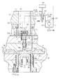
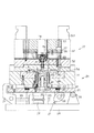
そこで、金型ユニット23の下型ユニット21と上型ユニット22の構成を図3を中心に説明する。
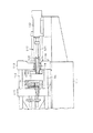
図3に示す下型ユニット21を構成する基板24は、図7に示す前記下部支持台11の上面に図示しないクランプ機構によって取り付けられるようになっている。この基板24の上面には水平支持板25がヒンジ機構26を介して上下方向の傾動可能に装着されている。前記基板24と水平支持板25との間には水平支持板25を傾動させるための傾動機構27が設けられている。この傾動機構27は前記基板24の上面に水平に支持した傾動用シリンダ28と、その傾動用シリンダ28のピストンロッド29によって作動されるカム部材30とにより構成されている。前記基板24の左端部にはロックレバー31が左右方向の傾動可能に支持され、前記傾動用シリンダ28の左端部に突出したピストンロッド33によってロックされた位置に保持されるようになっている。
Therefore, the configuration of the
A
前記水平支持板25の上面には左右1対(二箇所のみ図示)の円筒状をなす案内筒34が上方に向けて互いに平行に立設されている。各案内筒34には支持ロッド35が上向きにそれぞれ装設され、前記各案内筒34及び各支持ロッド35には鉄等の金属材料よりなる下型把持体36が上下方向の往復動可能に装着されている。前記下型把持体36の上面に設けた凹部には下型37が取り外し可能にボルト38によって締め付け固定されている。前記案内筒34の内部にはガスが封入され、支持ロッド35は、下型把持体36を常には所定高さ位置に弾性的に浮上保持するようにしている。
On the upper surface of the
前記水平支持板25の中央部上面には円筒状をなす台座39がボルトによって固着され、この台座39の上端部に形成された雄ネジ部391には、押出手段を構成する押出ロッド40の下部に形成した雌ネジ部401が螺合されている。前記台座39の中心部には、前記押出ロッド40に設けた冷却用ジャケット402に冷却水を供給するための冷却水供給部材41が収容され、外部から冷却水を供給するようになっている。
A
前記下型把持体36と下型37の中心部には円筒体42が上下方向に嵌入され、その下端外周に形成されたフランジがボルト43によって下型把持体36に締め付け固定されている。前記円筒体42の内周面にはライナー44が嵌入され、前記円筒体42の下端部にボルト45によって取り付けられたストッパー46によって所定位置に保持されている。前記押出ロッド40の上端部は前記ストッパー46に形成した挿通孔461と前記ライナー44の内周面441内に挿入されている。前記ライナー44の内周面441と押出ロッド40の上端面によって形成される有底円筒状の空間を溶湯等の被成型材料の貯留室47としている。この貯留室47内に溶湯Yが上方から注入されるようになっている。
A
前記水平支持板25の上面には案内ロッド48が複数箇所に立設され、各案内ロッド48には昇降可能に座金49が嵌装され、各座金49は積層された皿バネ50によって上方に付勢されている。前記下型把持体36の下面には前記案内ロッド48の頭部の進入を許容する凹部361が形成されている。
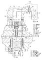
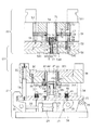
次に、前記昇降板15に装着される上型ユニット22について説明すると、金属材よりなる第1上型把持体51の上面には連結部材511が複数箇所に連結され、この連結部材511が図7に示す前記昇降板15の下面に対し図示しないクランプ機構により固着されるようになっている。前記第1上型把持体51の下面には第2上型把持体52がボルト53によって締め付け固定されている。この第2上型把持体52の下面には上型54が取り外し可能にボルト55によって締め付け固定されている。この上型54に形成された第2成型面541と、前記下型37に形成された第1成型面371とによって図1に示すように所定形状の製品を成型するためのキャビティKが形成されるようになっている。
Next, the
前記第1上型把持体51には、図3に示すように案内支柱56が複数箇所(四箇所のうち二箇所のみ図示)に設けられ、この案内支柱56には第1昇降板57及び第2昇降板58がボルト59によって連結された状態で図示しないシリンダにより同時に昇降可能に装着されている。前記第2昇降板58には案内ロッド60が複数箇所(図3に四箇所のうち一箇所図示)に下向きに連結され、各案内ロッド60は前記第2上型把持体52に形成された案内通路521及び上型54に形成された案内通路542に摺動可能に挿入されている。
As shown in FIG. 3, the first upper
前記第2昇降板58には押出ピン71の上端部が連結され、押出ピン71は第2上型把持体52、上型54に設けた案内通路523,544に挿入されている。
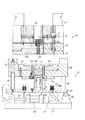
次に、図1,2を中心に本発明の特徴的構成について説明する。
An upper end portion of an
Next, the characteristic configuration of the present invention will be described with reference to FIGS.
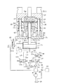
前記第2上型把持体52の中央部上面には円筒状をなす支持部材72が複数箇所にボルト73(図3参照)によって第2上型把持体52に締め付け固定されている。前記支持部材72の上面にはシリンダ74が下向きに設置され、ボルト75(図3参照)によって前記支持部材72の上面に締め付け固定されている。
A
図1に示すように、前記シリンダ74のピストンロッド76には加圧部材としての加圧ロッド77が連結されている。この加圧ロッド77の上端部に形成された雄ネジ771は、前記ピストンロッド76に形成された雌ネジ761に螺合されている。
As shown in FIG. 1, a
前記加圧ロッド77の中心部には冷却水の通路772が形成され、外部から冷却水が供給されるようにしている。前記加圧ロッド77の上端部にはフランジ部773が1体に形成されている。このフランジ部773には上下方向にキー溝774が形成され、前記第2上型把持体52の上部にはボルト82によってキー81が上下方向に指向するように固定され、このキー81が前記キー溝774に係合され、加圧ロッド77の回動が阻止されるようになっている。前記通路772の下端は密栓83によって閉鎖されている。
A cooling
前記第2上型把持体52及び上型54には、前記加圧ロッド77を上下方向に案内移動する案内通路524,545が形成されている。前記上型54に設けた案内通路545にはシール部材84が嵌入され、前記加圧ロッド77がこのシール部材84によって上下方向に案内移動されるようになっている。前記案内通路545と、加圧ロッド77の下端面とによって余剰の溶湯を収容するためのダンパー室Rが形成されている。
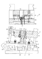
前記シリンダ74のピストン側シリンダ室91は、第1管路L1によって油タンク86及び油圧ポンプ87により構成された圧力流体供給源と接続されている。前記第1管路L1にはアキュームレータ88及び第1電磁切換弁89が接続され、第1電磁切換弁89とシリンダ74のロッド側シリンダ室92は、第2管路L2によって接続されている。前記第1電磁切換弁89は前記第1管路L1を介してピストン側シリンダ室91に圧油を供給して加圧ロッド77を前進させる供給ポート89aと、前記両室91,92をともにドレン状態とするドレンポート89bとの間で切換可能になっている。
The piston-
前記アキュームレータ88には油タンク86に油を還流する管路Lが接続され、該管路Lにはリリーフバルブ93が設けられ、制御装置94からの制御信号によって、アキュームレータ88内の圧力をほぼ一定の圧力に調整するようになっている。前記第1電磁切換弁89とシリンダ74の間の第1管路L1には第1圧力調整弁95が配設され、前記第1電磁切換弁89が加圧ロッド77を前進させる供給ポート89aに切り換えられた状態において、前記制御装置94からの制御信号によって、前記ピストン側シリンダ室91に供給する油圧力を調整するようになっている。又、第1電磁切換弁89が供給ポート89aからドレンポート89bに切り換えられると、ピストン側シリンダ室91内の油が第1管路L1を通して油タンク86に排出されるようになっている。このとき、前記第1圧力調整弁95は、制御装置94からの制御信号によって、ピストン側シリンダ室91から外部に排出される油の量を調整して、ピストン側シリンダ室91内の圧力を予め設定された設定圧力に制御する機能も兼用している。
The
この実施形態では、前記シリンダ74、ピストンロッド76、加圧ロッド77、油圧ポンプ87、アキュームレータ88、第1電磁切換弁89及び第1圧力調整弁95等によって加圧手段が構成されている。
In this embodiment, the
なお、前記下型ユニット21、上型ユニット22には図示しないが、下型37と上型54を冷却するための冷却機構が設けられている。
次に、前記のように構成した成型装置の動作について説明する。
Although not shown in the drawings, the
Next, the operation of the molding apparatus configured as described above will be described.
図3は図1に示す第1電磁切換弁89がドレンポート89bに保持され、下型ユニット21から上型ユニット22が上方に離隔された型開き状態を示し、加圧ロッド77が最下端位置に移動され、ダンパー室Rが最小の容積となっている。この状態において傾動用シリンダ28のピストンロッド33を後退(図3において右方へ移動)させ、手動によりロックレバー31のロック状態を解除する。そして、傾動機構27の傾動用シリンダ28のピストンロッド29を前進(図3において右方に移動)させてカム部材30を回動する。すると、図4に示すように水平支持板25及び下型把持体36等がヒンジ機構26を中心にして時計回り方向に回動される。この傾斜状態において前記貯留室47内に溶湯Yを注入する。なお、この傾斜角はカム部材30の形状を変更することにより例えば10°〜60°の範囲に設定が可能である。
FIG. 3 shows a mold open state in which the first
次に、前記傾動機構27のピストンロッド29を図4において後退させ、水平支持板25及び下型把持体36を図5に示すように元の水平状態に復帰する。その後、ピストンロッド33を左方へ移動させてロックレバー31を回動することにより水平支持板25の左端部を該ロックレバー31によりロックする。
Next, the piston rod 29 of the
次に、図6に示すように上型ユニット22を下方に移動して、上型54の下面が下型把持体36及び下型37の上面に接触する型閉め高さ位置に移動し、さらに、上型54によって下型把持体36を下方へ移動する。この下型把持体36の下降行程において押出ロッド40がライナー44内を上方に相対移動することになるので、貯留室47に貯留されていた溶湯YがキャビティK内に圧入される。このようにしてキャビティKの形状に倣った製品90が成型される。
Next, as shown in FIG. 6, the
図6においては、水平支持板25の上面に下型把持体36の下面に形成したストロークエンドを設定するストッパー(図示略)が接触して停止され、この状態で蓄勢された皿バネ50によって下型37が上型54に押圧される。下型37に対する上型54の型締め動作は、前記型締シリンダ18によって行われる。
In FIG. 6, a stopper (not shown) for setting a stroke end formed on the lower surface of the lower
前記キャビティK内に流入した溶湯Yのうちの余剰分は、加圧ロッド77を上方に移動しつつ、ダンパー室R内に進入する。この過程では両シリンダ室91,92がともにドレンポートになっているが、加圧ロッド77を上方に押し上げるときに所定の抵抗が付与されるように、第1管路L1に接続された第1圧力調整弁95によりピストン側シリンダ室91内の圧力が予め設定された設定圧力となるように制御される。
The surplus portion of the molten metal Y that has flowed into the cavity K enters the damper chamber R while moving the
加圧ロッド77が成型作業の最終段階で最上限位置に移動された後に、第1電磁切換弁89を制御装置94からの切換信号によりドレンポート89bから供給ポート89aに切り換えて、ピストン側シリンダ室91に圧油を供給し、シリンダ74の加圧ロッド77を下方に移動してダンパー室R内の余剰溶湯Yを加圧する。このとき、前記第1圧力調整弁95によりダンパー室Rの加圧力が予め設定された設定圧力に制御される。
After the
このようにして、製品90の製造が完了すると、型締シリンダ18が停止されるとともに、昇降用シリンダ16が作動されて、上型ユニット22が上方に移動され、上型把持体51及び上型54が製品90とともに上昇し、型開き状態に保持される。製品90は図示しないシリンダにより第1及び第2昇降板57,58を下方に移動して押出ピン71を下方に移動させることによって第2成型面541から分離される。
In this way, when the manufacture of the
上記実施形態の成型装置によれば、以下のような特徴を得ることができる。
(1)上記実施形態では、下型ユニット21の下型把持体36及び下型37内に溶湯Yの貯留室47を形成し、下型ユニット21と上型ユニット22の型閉め動作と同期して、貯留室47内の溶湯Yを押出ロッド40によってキャビティKに圧入するようにした。このため、従来のような外部装着タイプの射出機構が不要となり、構造を簡素化して成型装置を小型化することができるとともに、装置の製造を容易に行いコストの低減を図ることができる。又、下型ユニット21と上型ユニット22の型閉め動作と同期して貯留室47内の溶湯YをキャビティKに圧入する動作を行うことができ、成型作業の行程を一行程減らして作業能率を向上することができる。
According to the molding apparatus of the above embodiment, the following characteristics can be obtained.
(1) In the above embodiment, the
(2)上記実施形態では、前記上型54にダンパー室Rを形成し、加圧ロッド77を作動するシリンダ74のピストン側シリンダ室91の圧力が第1圧力調整弁95によって予め設定された設定圧力になるようにした。このため、貯留室47からキャビティK内に供給された溶湯Yの1部が前記加圧ロッド77を上方に押動してダンパー室Rに流入するので、余剰被成型材料としての余剰溶湯YをキャビティKから外部に逃すことができる。従って、下型37と上型54の型合わせ面に溶湯が侵入して製品の外形形状が損なわれるのを防止することができる。
(2) In the above embodiment, the damper chamber R is formed in the
又、貯留室47に対する溶湯Yの貯留量を厳密に管理しなくてもよいので、貯留室47への溶湯Yの注入作業を迅速に行い、成型作業の能率を向上することができる。
(3)前記実施形態では、押出ロッド40による溶湯Yの押し出し動作の開始時において、加圧ロッド77が前記ダンパー室Rの容積を最小にする位置に保持され、押し出し動作の最終段階で容積が最大となる位置に移動されるようにした。このため、貯留室47から押出ロッド40によってキャビティK内全域に溶湯Yが押し出された後に余剰の溶湯Yがダンパー室Rに進入するので、成型不良を未然に防止することができる。
In addition, since it is not necessary to strictly manage the amount of molten Y stored in the
(3) In the above embodiment, at the start of the extrusion operation of the molten metal Y by the
(4)上記実施形態では、押出ロッド40による溶湯YのキャビティKへの押し出し動作の最終段階で、前記第1電磁切換弁89をドレンポート89bから供給ポート89aに切り換えて、シリンダ74のピストンロッド76を下方に移動させるようにした。このため、加圧ロッド77によって余剰の溶湯を収容したダンパー室Rを加圧して、巣の発生を防止することができ、製品の硬度(密度)及び品質を向上することができる。
(4) In the above embodiment, at the final stage of the pushing operation of the molten metal Y to the cavity K by the
(5)上記実施形態では、図3に示す型開き状態で下型ユニット21の下型把持体36を傾動機構27によって傾斜位置に保持するようにした。このため、貯留室47内に溶湯Yを容易に注入することができるとともに、溶湯Yの泡立ち状態を無くして気泡が混入するのを防止することができる。
(5) In the above embodiment, the
(6)上記実施形態では、シリンダ74及び加圧ロッド77等により加圧手段を構成したので、該手段を安価に製造することができる。
(7)上記実施形態では、押出手段が押出ロッド40によって構成されているので、構成を簡素化し製造を容易に行いコストを低減することができる。
(6) In the above embodiment, since the pressurizing means is constituted by the
(7) In the above embodiment, since the extrusion means is constituted by the
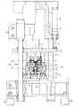
次に、この発明の別の実施形態を図8〜図10に基づいて説明する。なお、 この実施形態において、前述した実施形態と同様の機能を有する構成については、説明を省略あるいは簡略化する。 Next, another embodiment of the present invention will be described with reference to FIGS. In this embodiment, the description of the configuration having the same function as that of the above-described embodiment will be omitted or simplified.
この実施形態の成型装置においては、図8に示すように前記上型54側のダンパー室R及びその加圧手段が省略されている。前記第2上型把持体52に前記上型54を直接取り付けるとともに、前記水平支持板25の上面に支持台63を介して支持ロッド64を複数箇所に立設し、各支持ロッド64に対し前記下型把持体36に取り付けた案内筒65を昇降可能に装着している。前記案内筒65の下端面と、前記支持台63の上端面の間には、コイルバネ66が介在され、前記下型把持体36を常には上方に付勢するようにしている。前記第2上型把持体52の下面には前記支持ロッド64の上端部を挿入するための案内筒67が取り付けられている。
In the molding apparatus of this embodiment, as shown in FIG. 8, the damper chamber R on the
前記下型把持体36の下部には前記円筒体42の下端を支持する支持部材68が図示しないボルトによって下型把持体36に固着されている。前記水平支持板25の上面には、案内部材69が前記押出ロッド40を貫通するように取り付けられている。
A support member 68 that supports the lower end of the
前記水平支持板25の下面にはブラケット70を介して前記シリンダ74が上向きに装着され、前記ピストンロッド76の上端部は、前記押出ロッド40の下端部に連結されている。
The
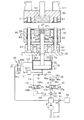
前記アキュームレータ88と、シリンダ74のピストン側シリンダ室91とは、第3管路L3及び第4管路L4によって並列に接続されている。前記第3管路L3には、第2電磁切換弁97、増速シリンダ98及び第1逆止弁99が接続されている。又、前記第4管路L4には第3電磁切換弁100及び第2逆止弁101が接続されている、前記増速シリンダ98はピストン98a、ロッド98b、加圧室98c及び該加圧室98cよりも容積の大きい作動室98dによって構成されている。そして、加圧室98cに圧油が供給されると、作動室98d内の圧油が前記ピストン側シリンダ室91に高速で供給されるようになっている。前記第2電磁切換弁97は、増速シリンダ98の加圧室98cに圧油を供給する供給ポート97aと、加圧室98cを油タンク86に連通するドレンポート97bとの間で切り換えるようになっている。前記第3電磁切換弁100は、前記ピストン側シリンダ室91に圧油を供給するための供給ポート100aと、第4管路L4を油タンク86に連通するドレンポート100bとの間で切り換えるようになっている。
The
前記第3管路L3にはシリンダ74のピストン側シリンダ室91に付加する圧力を低圧力に設定するための第2圧力調整弁102が接続され、第4管路L4には高圧力に設定するための第3圧力調整弁103が接続されている。
A second
前記制御装置94は、前記第1電磁切換弁89、第1圧力調整弁95の他に、前記第2,第3電磁切換弁97,100及び第2,第3圧力調整弁102,103に制御信号を出力するようになっている。その他の構成は、前述した実施形態の成型装置と同様である。
In addition to the first
この実施形態においては、前記貯留室47に前記ダンパー室Rの機能を兼用させ、押出ロッド40及びシリンダ74等に加圧手段の機能を兼用させている。
次に、上記のように構成した成型装置の成型動作について説明する。
In this embodiment, the function of the damper chamber R is also used for the
Next, the molding operation of the molding apparatus configured as described above will be described.
図8は、前記下型37がコイルバネ66によって所定高さ位置に保持されるとともに、上型54が下型37から上方に離隔された型開き状態を示す。この状態においては、前記第1電磁切換弁89、第2電磁切換弁97及び第3電磁切換弁100がそれぞれドレンポート89b,97b,100bに切り換えられ、前記シリンダ74のピストンロッド76及び押出ロッド40が最下限位置に保持されている。
FIG. 8 shows a mold open state in which the
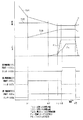
この状態において、成型装置により成型動作が開始されると、図10に示すタイミングチャートに基づいて、製品の成型動作が以下のように行われる。すなわち、前記上型54が図10の上型54の下降曲線T54に示すように早送りで下降動作される。そして、成型開始位置(時刻H1)に移動されると、上型54の下降速度が低減されて、上型54が低速で下降動作される。上型54が成型開始位置(時刻H1)に移動された時点で、前記第1電磁切換弁89がドレンポート89bから供給ポート89aに切り換えられるとともに、第2電磁切換弁97もドレンポート97bから供給ポート97aに切り換えられる。これによって、前記シリンダ74が作動されて、押出ロッド40が該押出ロッド40の上昇直線T40で示すように上方に移動され、貯留室47内に貯留されていた溶湯Yが型開き状態においてキャビティK(第1成型面371)へ移動される。
In this state, when the molding operation is started by the molding apparatus, the product molding operation is performed as follows based on the timing chart shown in FIG. That is, the
前記時刻H1から所定時間が経過した時刻H2になると、上型54が下型37の下降曲線T37で示すように、所定高さ位置に保持されていた下型37に接触され、下型37と上型54は同時に下降される。この型閉め時刻H2から所定時間が経過した時刻H3になると、下型37が下限位置に移動されて下型37及び上型54の下降動作が停止される。前記時刻H2以降においては、型閉め状態で、押出ロッド40が上昇されるので、キャビティKの圧力は、圧力曲線PKで示すように圧力上昇が開始される。又、時刻H3以降においては、下型37と上型54の移動が停止された状態で押出ロッド40が上昇されるので、圧力曲線PKに示すようにキャビティKの圧力が上昇する。さらに、前記時刻H3において前記型締シリンダ18が作動されて、下型37と上型54の型締めが行われ、時刻H4において型締め動作が完了する。前記型締シリンダ18による上型54の型締め圧力は、図10に圧力曲線Pcで示されている。この型締め動作が完了した時刻H4において、前記第2電磁切換弁97が供給ポート97aからドレンポート97bに切り換えられるとともに、第3電磁切換弁100がドレンポート100bから供給ポート100aに切り換えられ、シリンダ74のピストンロッド76によって押出ロッド40がさらに高い圧力で上方向に移動される。このため圧力曲線PKに示すように、キャビティKの圧力が上昇し、溶湯Yが加圧される。なお、時刻H4から所定時間経過した時刻H5において成型動作が終了し、第1電磁切換弁89がドレンポート89bに、第3電磁切換弁100もドレンポート100bにそれぞれ切り換えられ、下型37及び上型54が上昇され、シリンダ74のピストンロッド76及び押出ロッド40が下降動作される。
At time H2 when a predetermined time elapses from the time H1, the
図10の時刻H3において制御装置94からの制御信号により第2電磁切換弁97がドレンポート97bに切り換えられた後、例えば0.1〜2.0秒が経過してから同じく制御装置94からの制御信号により第3電磁切換弁100が供給ポート100aに切り換えられる。このため、圧力曲線PKはその間ほぼ一定圧力に保持される。このようにした理由は、キャビティK内の溶湯Yが凝固開始温度に達してから高圧で溶湯Yを加圧することによりヒケ巣(気泡)の発生を効果的に防止できるからである。前記0.1〜2.0秒の範囲のいずれにするかは、製品の肉厚寸法の厚薄によって前記凝固開始温度に達する時刻が異なるので、それに合うように制御装置94から出力される第2及び第3電磁切換弁97,100の切り換え制御信号を変更できるように構成されている。
After the second electromagnetic switching
上記の実施形態の成型装置の効果を以下に説明する。
(1)上記実施形態では、図10に示すように、時刻H1から時刻H2の間の型開き状態において、シリンダ74により押出ロッド40を上昇させて、貯留室47内の溶湯YをキャビティKに移動するようにした。このため、製品90が薄い肉厚寸法の場合に溶湯YをキャビティK内の薄肉形成部全体に迅速に供給することができ、この結果、薄い肉厚寸法の製品の成型を確実に行うことができる。
The effects of the molding apparatus of the above embodiment will be described below.
(1) In the above embodiment, as shown in FIG. 10, in the mold open state between time H1 and time H2, the
前記上型ユニット22の下降速度には限界があり、通常は0.4メートル/秒レベルであり、薄い肉厚寸法の製品90の成型には、1メートル/秒レベルの速度が要求される。このため、前記第3管路L3に増速シリンダ98を装着し、上型ユニット22が下降動作されて成型を行う際に、前記増速シリンダ98によりシリンダ74の押出ロッド40を速やかに上方へ移動して、成型速度の増速を図り、薄い肉厚寸法の製品90の成型を行うことができる。
The lowering speed of the
(2)上記実施形態では、時刻H4において、前記第3電磁切換弁100を供給ポート100aに切り換えて、シリンダ74のピストン側シリンダ室91に高い圧力を作用させ、押出ロッド40を上方へ押動し、溶湯Yを高い圧力で加圧するようにしたので、溶湯Yの内部のヒケ巣(気泡)を無くして製品の品質(硬度)を向上することができる。
(2) In the above embodiment, at time H4, the third
(3)上記実施形態では、前記貯留室47にダンパー室Rとしての機能を兼用させたので、前述した実施形態の成型装置と比較し、部品点数を低減し、製造を容易に行いコストの低減を図ることができる。
(3) In the above embodiment, since the
次に、この発明の別の実施形態を図11に基づいて説明する。
この実施形態においては、図8に示す実施形態のシリンダ74の下部に、ロッドレスタイプの加圧シリンダ105を装着するとともに、加圧シリンダ105のピストン106の上面側に前記ピストン側シリンダ室91を設け、下面側に加圧室107を形成している。前記ピストン側シリンダ室91には、第3管路L3が接続され、加圧室107には、第4管路L4が接続されている。又、前記第1逆止弁99及び第2逆止弁101は省略されている。その他の構成は、図8に示す実施形態の構成と同様である。
Next, another embodiment of the present invention will be described with reference to FIG.
In this embodiment, a rodless
この実施形態においては、加圧シリンダ105を設けたので、キャビティK内の圧力を高い圧力に設定することができる。その他の作用及び効果は図8に示す実施形態の作用及び効果と同様である。
In this embodiment, since the
なお、この発明は次のように変更して具体化することもできる。
○ 前記実施形態では溶湯を用いて製品の製造を行うようにしたが、被成型材料として個体と液体が共存する半凝固材料を用いて製品の成型を行うようにしてもよい。又、例えば200〜300℃に加熱された固体のアルミニウム等の金属の被成型材料を前記貯留室47内に収容して熱間成型するようにしてもよい。
In addition, this invention can also be changed and embodied as follows.
In the above embodiment, the product is manufactured using the molten metal. However, the product may be molded using a semi-solid material in which a solid and a liquid coexist as a material to be molded. Further, for example, a metal molding material such as solid aluminum heated to 200 to 300 ° C. may be accommodated in the
○ ヒンジ機構26及び傾動機構27を省略してもよい。
○ 前記各実施形態において前記下型ユニット21を、型閉め位置から前方又は後方に退避した位置に切り換えるようにしてもよい。
The
In the above embodiments, the
○ 前記加圧ロッド77を成型作業の開始前に上方に移動しておき、成型作業の途中でダンパー室Rに余剰溶湯を進入させ、成型作業の最終段階で加圧ロッド77を下方に移動して、ダンパー室Rの余剰溶湯を加圧するようにしてもよい。
○ The
○ 前記ダンパー室Rの形成位置を、下型37の第1成型面371又は上型54の第2成型面541の任意の位置に設定してもよい。
○ 図1に示す実施形態において、前記加圧ロッド77を成型作業の開始前に上方に移動してダンパー室Rを開放しておき、下型37と上型54の型合わせ後に押出ロッド40により溶湯YをキャビティK及びダンパー室Rに進入させる。その後、第1圧力調整弁95によりピストン側シリンダ室91の圧力を制御することにより、加圧ロッド77を低圧力で下方に移動しダンパー室Rの余剰溶湯を加圧し、所定時間経過後に高圧力で加圧ロッド77をさらに下方に移動するようにしてもよい。
The formation position of the damper chamber R may be set at an arbitrary position on the
In the embodiment shown in FIG. 1, the
この別例では、ダンパー室Rの余剰溶湯をキャビティKへ流入させてキャビティ内の溶湯の充填状態のバラツキを無くすことができる。又、高圧力で余剰溶湯を加圧するので、成型された製品にヒケ巣(気泡)ができるのを防止することができる。 In this other example, the excess molten metal in the damper chamber R can be caused to flow into the cavity K to eliminate variations in the filling state of the molten metal in the cavity. Moreover, since the excess molten metal is pressurized at a high pressure, it is possible to prevent the formation of a sink nest (bubble) in the molded product.
○ 図1に示す実施形態において、加圧手段の加圧部材(加圧ロッド77)が、押出手段(押出ロッド40)による被成型材料の押し出し動作の開始時にダンパー室Rの容積を最大にする位置に保持され、貯留室47の被成型材料のキャビティKへの押し出し動作が終了した後に加圧部材により低圧力でダンパー室Rの余剰溶湯を加圧し、次に、高圧力で余剰溶湯を加圧するように構成してもよい。
In the embodiment shown in FIG. 1, the pressurizing member (pressurizing rod 77) of the pressurizing means maximizes the volume of the damper chamber R at the start of the extrusion operation of the molding material by the extruding means (extrusion rod 40). After the operation of pushing the molding material in the
この別例では、貯留室47の溶湯YのキャビティKへの押し出し動作が終了した後に加圧部材により低圧力で前記ダンパー室Rの余剰溶湯を加圧するので、ダンパー室Rの余剰溶湯をキャビティKへ流入させてキャビティ内の溶湯の充填状態のバラツキを無くすことができる。又、高圧力で余剰溶湯を加圧するので、成型された製品にヒケ巣ができるのを防止することができる。
In this alternative example, after the operation of pushing out the molten metal Y in the
○ 前記押出ロッド40の配設位置を適宜に変更してもよい。
○ 第1型ユニットと第2型ユニットを水平方向に接近又は離間可能に対向して配置し、前記両型ユニットの少なくとも一方の型ユニットの内部にキャビティに連通する被成型材料の貯留室を設け、該貯留室に押出ロッドを設けた成型装置に具体化してもよい。
(Circle) you may change the arrangement | positioning position of the said
○ The first mold unit and the second mold unit are arranged facing each other so as to be close to or away from each other in the horizontal direction, and a storage chamber for the molding material communicating with the cavity is provided inside at least one of the mold units. In addition, the storage chamber may be embodied in a molding apparatus provided with an extrusion rod.
○ 前記第1圧力調整弁95の設置位置を、第1電磁切換弁89のドレンポート89bと油タンク86の間の第2管路L2に変更してもよい。
○ 前記増速シリンダ98を省略してもよい。
The installation position of the first
The
K…キャビティ、L…管路、R…ダンパー室、Y…余剰溶湯、L1…第1管路、L2…第2管路、L3…第3管路、L4…第4管路、17,19,29,33,76…ピストンロッド、21…下型ユニット、22…上型ユニット、40…押出ロッド、47…貯留室、89…第1電磁切換弁、89a,97a,100a…供給ポート、89b,97b,100b…ドレンポート、91,92…シリンダ室、91…ピストン側シリンダ室、92…ロッド側シリンダ室、94…制御装置、95…第1圧力調整弁、97…第2電磁切換弁、98…増速シリンダ、98c,107…加圧室、99…第1逆止弁、100…第3電磁切換弁、101…第2逆止弁、102…第2圧力調整弁、103…第3圧力調整弁。
K ... cavity, L ... pipe, R ... damper chamber, Y ... surplus molten metal, L1 ... first pipe, L2 ... second pipe, L3 ... third pipe, L4 ... fourth pipe, 17, 19 , 29, 33, 76 ... piston rod, 21 ... lower mold unit, 22 ... upper mold unit, 40 ... push rod, 47 ... storage chamber, 89 ... first electromagnetic switching valve, 89a, 97a, 100a ... supply port,
Claims (10)
Priority Applications (6)
| Application Number | Priority Date | Filing Date | Title |
|---|---|---|---|
| JP2005055057A JP4319996B2 (en) | 2004-03-18 | 2005-02-28 | Molding device |
| EP05445014A EP1598130A1 (en) | 2004-03-18 | 2005-03-17 | Pressure die casting device |
| KR1020050022205A KR20060043751A (en) | 2004-03-18 | 2005-03-17 | Molding equipment |
| CNA2005100559242A CN1669702A (en) | 2004-03-18 | 2005-03-18 | Molding device |
| US11/083,791 US7111664B2 (en) | 2004-03-18 | 2005-03-18 | Molding device |
| TW094108286A TW200600228A (en) | 2004-03-18 | 2005-03-18 | Molding device |
Applications Claiming Priority (2)
| Application Number | Priority Date | Filing Date | Title |
|---|---|---|---|
| JP2004078947 | 2004-03-18 | ||
| JP2005055057A JP4319996B2 (en) | 2004-03-18 | 2005-02-28 | Molding device |
Related Child Applications (1)
| Application Number | Title | Priority Date | Filing Date |
|---|---|---|---|
| JP2008333010A Division JP4699509B2 (en) | 2004-03-18 | 2008-12-26 | Molding device |
Publications (2)
| Publication Number | Publication Date |
|---|---|
| JP2005297061A true JP2005297061A (en) | 2005-10-27 |
| JP4319996B2 JP4319996B2 (en) | 2009-08-26 |
Family
ID=34943235
Family Applications (1)
| Application Number | Title | Priority Date | Filing Date |
|---|---|---|---|
| JP2005055057A Expired - Lifetime JP4319996B2 (en) | 2004-03-18 | 2005-02-28 | Molding device |
Country Status (6)
| Country | Link |
|---|---|
| US (1) | US7111664B2 (en) |
| EP (1) | EP1598130A1 (en) |
| JP (1) | JP4319996B2 (en) |
| KR (1) | KR20060043751A (en) |
| CN (1) | CN1669702A (en) |
| TW (1) | TW200600228A (en) |
Cited By (5)
| Publication number | Priority date | Publication date | Assignee | Title |
|---|---|---|---|---|
| JP2009039756A (en) * | 2007-08-09 | 2009-02-26 | Kimura Kogyo:Kk | Method for feeding molten metal to storage chamber in molding device, and apparatus therefor |
| CN103273620A (en) * | 2013-05-08 | 2013-09-04 | 宁波市佳利来机械制造有限公司 | Aluminum alloy connector mold with slide block thimble |
| CN106345957A (en) * | 2016-11-29 | 2017-01-25 | 洛阳秦汉精工股份有限公司 | Semi-solid-state die forging mold device |
| CN106378407A (en) * | 2016-11-29 | 2017-02-08 | 洛阳秦汉精工股份有限公司 | Composite semisolid stamp-forging mold device |
| CN112207249A (en) * | 2019-07-12 | 2021-01-12 | 菲尼克斯电气公司 | Casting device and method for producing a component from a melt |
Families Citing this family (4)
| Publication number | Priority date | Publication date | Assignee | Title |
|---|---|---|---|---|
| DE102006057786A1 (en) * | 2006-12-06 | 2008-06-12 | Almecon Entwicklungs-, Beratungs- Und Beschaffungsgesellschaft Mbh | Method for producing mold part made of light metal/light metal alloy by a pressing device, comprises opening molding tool of the pressing device subjectable with first pressing force and movable in vertical direction in starting position |
| CN101780534A (en) * | 2009-01-20 | 2010-07-21 | 苏州三基机械有限公司 | Novel extrusion injection device |
| CN104493112B (en) * | 2015-01-06 | 2016-11-02 | 中冶京诚工程技术有限公司 | Steel ingot casting mold and casting method |
| EP4327961A1 (en) * | 2022-08-22 | 2024-02-28 | Nemak, S.A.B. de C.V. | Apparatus for applying force to a metal component in a casting mold, method and use of an apparatus |
Citations (10)
| Publication number | Priority date | Publication date | Assignee | Title |
|---|---|---|---|---|
| JPS56102365A (en) * | 1980-01-21 | 1981-08-15 | Honda Motor Co Ltd | Method of filling molten metal in vertical type die casting machine |
| JPS5797861A (en) * | 1980-12-10 | 1982-06-17 | Toyota Motor Corp | Pressure casting method |
| JPS62207560A (en) * | 1986-03-07 | 1987-09-11 | Mazda Motor Corp | Injection control device for vertical type die casting machine |
| JPH02101715U (en) * | 1989-01-30 | 1990-08-14 | ||
| JPH05305412A (en) * | 1992-05-01 | 1993-11-19 | Toyota Motor Corp | Casting apparatus |
| JPH0833966A (en) * | 1994-07-21 | 1996-02-06 | Toyota Motor Corp | Die casting machine |
| JPH08215824A (en) * | 1995-02-21 | 1996-08-27 | Kobe Steel Ltd | Method and device for extruding product of high pressure casting machine and the like |
| JPH1024357A (en) * | 1996-07-11 | 1998-01-27 | U Mold:Kk | Injection molding method and equipment |
| JPH10146663A (en) * | 1996-11-18 | 1998-06-02 | U Mold:Kk | Vertical casting method and apparatus |
| JP2001300715A (en) * | 2000-04-26 | 2001-10-30 | Toshiba Mach Co Ltd | Die casting apparatus |
Family Cites Families (11)
| Publication number | Priority date | Publication date | Assignee | Title |
|---|---|---|---|---|
| US2411999A (en) * | 1942-05-19 | 1946-12-03 | Lester Engineering Co | Pressure extrusion molding |
| DE2953474C2 (en) * | 1979-02-14 | 1984-06-07 | Nippondenso Co., Ltd., Kariya, Aichi | Die-casting process with redensification |
| JPS62101366A (en) * | 1985-10-29 | 1987-05-11 | Mazda Motor Corp | Molten metal forging device |
| DE3879285T2 (en) * | 1987-06-13 | 1993-07-01 | Honda Motor Co Ltd | HYDRAULIC CHECKING PROCEDURE FOR TOOLS. |
| JPS6453750A (en) * | 1987-08-24 | 1989-03-01 | Honda Motor Co Ltd | Secondary pressurizing casting method |
| SE465557B (en) * | 1988-06-13 | 1991-09-30 | Tour & Andersson Ab | SET AND DEVICE FOR PRIMING |
| JPH07227667A (en) * | 1994-02-22 | 1995-08-29 | Toyota Motor Corp | Die casting |
| JPH09239511A (en) * | 1996-03-04 | 1997-09-16 | Toyota Motor Corp | Casting mold air blow method and air blow built-in casting mold |
| ITMI991586A1 (en) * | 1999-07-16 | 2001-01-16 | T C S Molding Systems S P A | VERTICAL PRESS FOR THE MOLDING OF DIE-CAST PARTS |
| US7174947B2 (en) * | 2001-07-31 | 2007-02-13 | Peter B. Olmsted Trust | Method of sizing overflow chambers |
| JP3921513B2 (en) * | 2002-04-17 | 2007-05-30 | 株式会社木村工業 | Molding apparatus and mold unit used therefor |
-
2005
- 2005-02-28 JP JP2005055057A patent/JP4319996B2/en not_active Expired - Lifetime
- 2005-03-17 KR KR1020050022205A patent/KR20060043751A/en not_active Ceased
- 2005-03-17 EP EP05445014A patent/EP1598130A1/en not_active Withdrawn
- 2005-03-18 TW TW094108286A patent/TW200600228A/en unknown
- 2005-03-18 US US11/083,791 patent/US7111664B2/en not_active Expired - Fee Related
- 2005-03-18 CN CNA2005100559242A patent/CN1669702A/en active Pending
Patent Citations (10)
| Publication number | Priority date | Publication date | Assignee | Title |
|---|---|---|---|---|
| JPS56102365A (en) * | 1980-01-21 | 1981-08-15 | Honda Motor Co Ltd | Method of filling molten metal in vertical type die casting machine |
| JPS5797861A (en) * | 1980-12-10 | 1982-06-17 | Toyota Motor Corp | Pressure casting method |
| JPS62207560A (en) * | 1986-03-07 | 1987-09-11 | Mazda Motor Corp | Injection control device for vertical type die casting machine |
| JPH02101715U (en) * | 1989-01-30 | 1990-08-14 | ||
| JPH05305412A (en) * | 1992-05-01 | 1993-11-19 | Toyota Motor Corp | Casting apparatus |
| JPH0833966A (en) * | 1994-07-21 | 1996-02-06 | Toyota Motor Corp | Die casting machine |
| JPH08215824A (en) * | 1995-02-21 | 1996-08-27 | Kobe Steel Ltd | Method and device for extruding product of high pressure casting machine and the like |
| JPH1024357A (en) * | 1996-07-11 | 1998-01-27 | U Mold:Kk | Injection molding method and equipment |
| JPH10146663A (en) * | 1996-11-18 | 1998-06-02 | U Mold:Kk | Vertical casting method and apparatus |
| JP2001300715A (en) * | 2000-04-26 | 2001-10-30 | Toshiba Mach Co Ltd | Die casting apparatus |
Cited By (6)
| Publication number | Priority date | Publication date | Assignee | Title |
|---|---|---|---|---|
| JP2009039756A (en) * | 2007-08-09 | 2009-02-26 | Kimura Kogyo:Kk | Method for feeding molten metal to storage chamber in molding device, and apparatus therefor |
| CN103273620A (en) * | 2013-05-08 | 2013-09-04 | 宁波市佳利来机械制造有限公司 | Aluminum alloy connector mold with slide block thimble |
| CN106345957A (en) * | 2016-11-29 | 2017-01-25 | 洛阳秦汉精工股份有限公司 | Semi-solid-state die forging mold device |
| CN106378407A (en) * | 2016-11-29 | 2017-02-08 | 洛阳秦汉精工股份有限公司 | Composite semisolid stamp-forging mold device |
| CN112207249A (en) * | 2019-07-12 | 2021-01-12 | 菲尼克斯电气公司 | Casting device and method for producing a component from a melt |
| CN112207249B (en) * | 2019-07-12 | 2022-05-10 | 菲尼克斯电气公司 | Casting device and method for producing a component from a melt |
Also Published As
| Publication number | Publication date |
|---|---|
| JP4319996B2 (en) | 2009-08-26 |
| US7111664B2 (en) | 2006-09-26 |
| KR20060043751A (en) | 2006-05-15 |
| CN1669702A (en) | 2005-09-21 |
| TW200600228A (en) | 2006-01-01 |
| US20050205231A1 (en) | 2005-09-22 |
| EP1598130A1 (en) | 2005-11-23 |
Similar Documents
| Publication | Publication Date | Title |
|---|---|---|
| JP3921513B2 (en) | Molding apparatus and mold unit used therefor | |
| CN109128080B (en) | Cold chamber die casting machine with horizontal liquid feeding and vertical injection and extrusion casting method | |
| US4265102A (en) | Method for molding a bulge | |
| JP2005297061A (en) | Molding device | |
| JP4699509B2 (en) | Molding device | |
| CA2028780C (en) | Rotary type injection orientation blow molding machine | |
| US7004224B2 (en) | Diecasting machine | |
| JP2009131868A (en) | Booster for boosting accumulator in die-casting machine and controlling method thereof | |
| CN119346833B (en) | Casting device for precision casting | |
| CN114871402B (en) | Die casting machine, pressure casting method, and cavity opening on-off switching method and device | |
| JP2002240116A (en) | Mold clamping device for injection molding and injection molding device | |
| JP5209246B2 (en) | Molding equipment | |
| JP4472486B2 (en) | Molding device | |
| US4154287A (en) | Apparatus for manufacturing fusible patterns | |
| CN115365496B (en) | Tooling equipment for manufacturing magnetic ring | |
| US6103174A (en) | Mold clamping method for straight hydraulic mold clamping apparatus | |
| JPH0414419A (en) | Transfer mold apparatus | |
| JPH0534847Y2 (en) | ||
| JP2009039756A (en) | Method for feeding molten metal to storage chamber in molding device, and apparatus therefor | |
| CN218574914U (en) | Machine for casting aluminum piston blank by turning 180 degrees | |
| KR102347160B1 (en) | Vertical injection type diecasting machine | |
| JPH09267372A (en) | Injection molding machine | |
| KR20260048907A (en) | Hot forging mold device for low pressure casting | |
| JPH1199530A (en) | Synthetic resin compression molding device and molding method | |
| CN107639143A (en) | For patch mold forming method and equipment with internal cavity thin wall metalwork |
Legal Events
| Date | Code | Title | Description |
|---|---|---|---|
| A621 | Written request for application examination |
Free format text: JAPANESE INTERMEDIATE CODE: A621 Effective date: 20060711 |
|
| A711 | Notification of change in applicant |
Free format text: JAPANESE INTERMEDIATE CODE: A711 Effective date: 20070105 |
|
| A977 | Report on retrieval |
Free format text: JAPANESE INTERMEDIATE CODE: A971007 Effective date: 20080522 |
|
| A131 | Notification of reasons for refusal |
Free format text: JAPANESE INTERMEDIATE CODE: A131 Effective date: 20080603 |
|
| A521 | Request for written amendment filed |
Free format text: JAPANESE INTERMEDIATE CODE: A523 Effective date: 20080730 |
|
| A131 | Notification of reasons for refusal |
Free format text: JAPANESE INTERMEDIATE CODE: A131 Effective date: 20081028 |
|
| A521 | Request for written amendment filed |
Free format text: JAPANESE INTERMEDIATE CODE: A523 Effective date: 20081226 |
|
| TRDD | Decision of grant or rejection written | ||
| A01 | Written decision to grant a patent or to grant a registration (utility model) |
Free format text: JAPANESE INTERMEDIATE CODE: A01 Effective date: 20090512 |
|
| A01 | Written decision to grant a patent or to grant a registration (utility model) |
Free format text: JAPANESE INTERMEDIATE CODE: A01 |
|
| A61 | First payment of annual fees (during grant procedure) |
Free format text: JAPANESE INTERMEDIATE CODE: A61 Effective date: 20090529 |
|
| FPAY | Renewal fee payment (event date is renewal date of database) |
Free format text: PAYMENT UNTIL: 20120605 Year of fee payment: 3 |
|
| R150 | Certificate of patent or registration of utility model |
Ref document number: 4319996 Country of ref document: JP Free format text: JAPANESE INTERMEDIATE CODE: R150 |
|
| FPAY | Renewal fee payment (event date is renewal date of database) |
Free format text: PAYMENT UNTIL: 20150605 Year of fee payment: 6 |
|
| R250 | Receipt of annual fees |
Free format text: JAPANESE INTERMEDIATE CODE: R250 |
|
| R250 | Receipt of annual fees |
Free format text: JAPANESE INTERMEDIATE CODE: R250 |
|
| R250 | Receipt of annual fees |
Free format text: JAPANESE INTERMEDIATE CODE: R250 |
|
| R250 | Receipt of annual fees |
Free format text: JAPANESE INTERMEDIATE CODE: R250 |
|
| R250 | Receipt of annual fees |
Free format text: JAPANESE INTERMEDIATE CODE: R250 |
|
| EXPY | Cancellation because of completion of term |