JP2005297056A - Workpiece separating equipment - Google Patents
Workpiece separating equipment Download PDFInfo
- Publication number
- JP2005297056A JP2005297056A JP2004121245A JP2004121245A JP2005297056A JP 2005297056 A JP2005297056 A JP 2005297056A JP 2004121245 A JP2004121245 A JP 2004121245A JP 2004121245 A JP2004121245 A JP 2004121245A JP 2005297056 A JP2005297056 A JP 2005297056A
- Authority
- JP
- Japan
- Prior art keywords
- workpiece
- work
- cylinder
- welding
- workpieces
- Prior art date
- Legal status (The legal status is an assumption and is not a legal conclusion. Google has not performed a legal analysis and makes no representation as to the accuracy of the status listed.)
- Granted
Links
- 238000003466 welding Methods 0.000 claims abstract description 108
- 230000007246 mechanism Effects 0.000 claims abstract description 43
- 239000000463 material Substances 0.000 claims description 11
- 238000003825 pressing Methods 0.000 claims description 11
- 238000005452 bending Methods 0.000 claims description 8
- 238000000926 separation method Methods 0.000 claims description 8
- 229910052751 metal Inorganic materials 0.000 claims description 7
- 239000002184 metal Substances 0.000 claims description 7
- 238000005096 rolling process Methods 0.000 claims description 3
- 230000005540 biological transmission Effects 0.000 description 11
- 238000012546 transfer Methods 0.000 description 11
- 239000007789 gas Substances 0.000 description 6
- 239000000498 cooling water Substances 0.000 description 5
- 238000006073 displacement reaction Methods 0.000 description 5
- 239000012530 fluid Substances 0.000 description 5
- 238000003780 insertion Methods 0.000 description 5
- 230000037431 insertion Effects 0.000 description 5
- 238000011144 upstream manufacturing Methods 0.000 description 5
- 238000005520 cutting process Methods 0.000 description 4
- 238000001514 detection method Methods 0.000 description 4
- 230000003287 optical effect Effects 0.000 description 4
- 229910001220 stainless steel Inorganic materials 0.000 description 4
- 239000010935 stainless steel Substances 0.000 description 4
- 230000009471 action Effects 0.000 description 3
- 239000011324 bead Substances 0.000 description 3
- 230000001105 regulatory effect Effects 0.000 description 3
- WFKWXMTUELFFGS-UHFFFAOYSA-N tungsten Chemical compound [W] WFKWXMTUELFFGS-UHFFFAOYSA-N 0.000 description 3
- 229910052721 tungsten Inorganic materials 0.000 description 3
- 239000010937 tungsten Substances 0.000 description 3
- XKRFYHLGVUSROY-UHFFFAOYSA-N Argon Chemical compound [Ar] XKRFYHLGVUSROY-UHFFFAOYSA-N 0.000 description 2
- 238000001816 cooling Methods 0.000 description 2
- 238000002844 melting Methods 0.000 description 2
- 230000008018 melting Effects 0.000 description 2
- 230000002093 peripheral effect Effects 0.000 description 2
- 230000032258 transport Effects 0.000 description 2
- RYGMFSIKBFXOCR-UHFFFAOYSA-N Copper Chemical compound [Cu] RYGMFSIKBFXOCR-UHFFFAOYSA-N 0.000 description 1
- 229920006311 Urethane elastomer Polymers 0.000 description 1
- 238000013459 approach Methods 0.000 description 1
- 229910052786 argon Inorganic materials 0.000 description 1
- 230000000903 blocking effect Effects 0.000 description 1
- 230000008859 change Effects 0.000 description 1
- 239000012141 concentrate Substances 0.000 description 1
- 230000008602 contraction Effects 0.000 description 1
- 230000001276 controlling effect Effects 0.000 description 1
- 229910052802 copper Inorganic materials 0.000 description 1
- 239000010949 copper Substances 0.000 description 1
- 230000002542 deteriorative effect Effects 0.000 description 1
- 229920001971 elastomer Polymers 0.000 description 1
- 230000003028 elevating effect Effects 0.000 description 1
- 239000011261 inert gas Substances 0.000 description 1
- 238000000034 method Methods 0.000 description 1
- 238000012544 monitoring process Methods 0.000 description 1
- 229920001084 poly(chloroprene) Polymers 0.000 description 1
- 238000012545 processing Methods 0.000 description 1
- 230000009467 reduction Effects 0.000 description 1
- 230000001360 synchronised effect Effects 0.000 description 1
- XLYOFNOQVPJJNP-UHFFFAOYSA-N water Substances O XLYOFNOQVPJJNP-UHFFFAOYSA-N 0.000 description 1
Images

Landscapes
- Butt Welding And Welding Of Specific Article (AREA)
Abstract
Description
本発明は、ステンレス鋼板等の金属板材を円筒状に曲げ加工して成る複数のワークをそのスリット部が夫々真上を向くように配置し、各ワークを直列状に連ねた状態で軸線方向へ搬送しつつ各ワークのスリット部を順次突合せ溶接して円筒状の単管を連続的に製造する単管連続自動溶接装置に使用されるものであり、溶接により端部同士が接合された状態で搬送されてくる複数のワークを夫々単一のワークに切り離すワーク切り離し装置に関するものである。 In the present invention, a plurality of workpieces formed by bending a metal plate material such as a stainless steel plate into a cylindrical shape are arranged so that the slit portions thereof are directed directly above, and the workpieces are connected in series in the axial direction. It is used for single-tube continuous automatic welding equipment that continuously manufactures cylindrical single pipes by butt welding the slits of each workpiece sequentially while being transported, with the ends joined together by welding. The present invention relates to a workpiece separating apparatus that separates a plurality of conveyed workpieces into a single workpiece.
一般に、ステンレス鋼板等の金属板材を円筒状に曲げ加工して成る複数のワークから単管を連続的に製造する単管連続自動溶接装置に於いては、複数のワークをそのスリット部が夫々同じ位置になるように揃えて配置し、各ワークを直列状に連ねた状態で軸線方向へ搬送しつつ各ワークのスリット部を順次突合せ溶接して円筒状の単管を連続的に製造するようにしている。そのため、スリット部を突合せ溶接された各ワークは、連続溶接により隣接するワークの端部同士がビード部分で接合された状態で搬送されることになり、途中で単一のワークに切り離す必要がある。 In general, in a single-tube continuous automatic welding apparatus that continuously manufactures a single tube from a plurality of workpieces formed by bending a metal plate material such as a stainless steel plate into a cylindrical shape, the slit portions of the plurality of workpieces are the same. A cylindrical single tube is continuously manufactured by sequentially butt welding the slits of each workpiece while conveying them in the axial direction with the workpieces connected in series. ing. Therefore, each work butt-welded at the slit portion is transported in a state in which the ends of adjacent works are joined by a bead portion by continuous welding, and it is necessary to cut it into a single work in the middle. .
従来、溶接により端部同士が接合された状態で搬送されて来る複数のワークを単一のワークに切り離す装置としては、搬送されて来る先頭のワークを端部接合部で切断するようにしたワーク分離装置(例えば、特許文献1)が知られている。
即ち、前記ワーク分離装置(図示省略)は、接合された状態で送られて来る先頭のワークをその溶接部分を中心にして正逆方向に回転させる回転段と、回転手段をワークの送り速度に同調させて移動させる移動手段とを備えており、移動手段によりワークの送り速度に同調させながら回転手段を作動させると共に、この回転手段により接合状態で送られて来る各ワークをその溶接部分を中心に正逆方向に回転させ、ワークの溶接部分(端部接合部)をねじり作用で切断することによって、接合された状態で送られて来る複数のワークを夫々単一のワークに分離するようにしたものである。
Conventionally, as a device that separates multiple workpieces that are transported in a state where the ends are joined together by welding into a single workpiece, the workpiece that cuts the leading workpiece that is transported at the end joint A separation device (for example, Patent Document 1) is known.
That is, the workpiece separating device (not shown) has a rotation stage for rotating the leading workpiece fed in a joined state in the forward and reverse directions around the welded portion, and the rotating means at the workpiece feed rate. Moving means that moves in synchronism with each other. The rotating means is operated while being synchronized with the feed speed of the work by the moving means, and each work sent in a joined state by the rotating means is centered on the welded portion. In order to separate the multiple workpieces sent in the joined state into a single workpiece by rotating the workpiece in the forward and reverse directions and cutting the welded part (end joint) of the workpiece by torsional action. It is a thing.
然し乍ら、前記ワーク分離装置は、ワークの溶接部分を切断する際に回転手段がワークをその溶接部分を中心にして回転させるのではなく、実際には回転手段がワークの溶接部分を引き千切るようにして切断しているため、ワーク端面の溶接部分にくびれた部分や突起が発生することがあり、製品(単管)の品質が著しく低下すると云う問題がある。
又、このワーク分離装置は、ワークの溶接部分を切断する際に回転手段によりワークを正逆回転させたり、回転手段を移動手段によりワークの送り方向へワークと同じ速度で移動させたりしなければならないため、装置自体の構造が複雑化して組立の煩雑化やコストの高騰等を招くと云う問題もある。
However, when the workpiece separating apparatus cuts the welded portion of the workpiece, the rotating means does not rotate the workpiece around the welded portion, but the rotating means actually cuts the welded portion of the workpiece. Therefore, there is a problem that a constricted portion or a projection may be generated in the welded portion of the workpiece end surface, and the quality of the product (single pipe) is significantly deteriorated.
In addition, when the workpiece separating apparatus cuts the welded portion of the workpiece, the workpiece must be rotated forward or reverse by the rotating means, or the rotating means must be moved by the moving means in the workpiece feeding direction at the same speed as the workpiece. Therefore, there is a problem that the structure of the apparatus itself is complicated, resulting in complicated assembly and high cost.
一方、本件出願人は、円筒状に曲げ加工して成る複数のワークを直列状に連ねた状態で軸線方向へ搬送し、各ワークの搬送中に夫々のスリット部を順次突合せ溶接して円筒状の単管を連続的に製造する単管連続自動溶接装置を開発し、これを先に特許出願(特願2003−376084)している。この単管連続自動溶接装置には、溶接により端部同士が接合された状態で搬送されて来る複数のワークを夫々単一のワークに切り離すワーク切り離し装置が組み込まれている。 On the other hand, the applicant of the present invention transports a plurality of workpieces formed by bending into a cylindrical shape in an axial direction in a state of being connected in series, and sequentially butt welds each slit portion during the transport of each workpiece to form a cylindrical shape. Has developed a single-tube continuous automatic welding apparatus that continuously manufactures a single-tube and has applied for a patent (Japanese Patent Application No. 2003-376084). The single pipe continuous automatic welding apparatus incorporates a workpiece separating device that separates a plurality of workpieces conveyed in a state where the end portions are joined together by welding into a single workpiece.
即ち、前記ワーク切り離し装置70は、図13に示す如く、キャタピラ式コンベヤ等から成るワーク搬送装置(図示省略)の下流側位置に縦向き姿勢で配置され、先頭に位置するワークWを上方へ突き上げる突き上げローラ71aを備えた突き上げシリンダ71と、突き上げローラ71aの近傍位置に傾斜姿勢で配設され、切り離されたワークWを搬出する搬出シュート72とから構成されており、ワーク搬送装置から送り出されて環状のワーク保持具73を通過したワークWを突き上げシリンダ71の突き上げローラ71aにより数回連続的に突き上げ、ワークWの端部接合部に衝撃を与えることによって、ワークWの端部接合部を切り離すようにしたものである。
That is, as shown in FIG. 13, the
このワーク切り離し装置70は、ワークWをその端部接合部を支点にして上方へ折り曲げて切り離すようにしているため、ワークWの溶接部分を引き千切るようにした上述のワーク分離装置に比較してワークW端面が比較的奇麗な形状となり、製品(単管)の品質が低下するのを防止することができる。然も、このワーク切り離し装置は、構造自体もワーク分離装置に比較して極めて簡単であり、組立の簡略化やコスト低減等を図れることになる。
Since the
然し乍ら、上述したワーク切り離し装置70にも、未だ解決すべき問題点が残されている。
即ち、前記ワーク切り離し装置70は、ワークWを突き上げシリンダ71で上方へ突き上げているときでも、ワークWがワーク搬送装置により連続的に前方へ搬送されて来るため、突き上げシリンダ71が順次送られて来るワークWによりワークWの搬送方向へ強く押圧され、上方へ突き上げられたワークWの端部接合部(支点)と突き上げシリンダ71のワークWに当接している部分(作用点)とに大きな力が発生し、突き上げシリンダ71のロッド71bが下降できないときがある。この状態でワークWが更に前方へ搬送されると、ワークWの端部に変形が生じるばかりでなく、装置自体の運転を停止しなければないらないことになる。
又、ワーク切り離し装置70は、ワークWの長さが比較的長い場合にはワークWを突き上げシリンダ71で突き上げても、ワークWが自重により下方へ降りて来るため、再度突き上げシリンダ71によりワークWを突き上げることができるが、ワークWの長さが短い場合にはワークWが軽いために自重では降りて来ず、ワークWが端部接合部を支点にして上方へ折れ曲がったままの状態となり、ワークWの切り離しを行えないと云う問題が発生している。
更に、ワーク切り離し装置70は、端部同士が接合されているワークWを切り離す際に突き上げシリンダ71によりワークWを下方から上方へ突き上げるようにしているため、切り離されたワークWが色々な方向へ飛んで行き、搬出シュート72へ搬出されなかったり、或いは搬出シュート72へ搬出されてもワークWの向きがバラバラになると云う問題が発生している。
That is, even when the
Further, when the workpiece W has a relatively long length, the
Furthermore, since the
本発明は、このような問題点に鑑みて為されたものであり、その目的は、溶接により端部同士が接合された状態で搬送されて来るワークの切り離しを確実且つ良好に行えると共に、切り離されたワークを整然とした姿勢で搬出することができるようにしたワーク切り離し装置を提供することにある。 The present invention has been made in view of such problems, and the object thereof is to reliably and satisfactorily separate the workpieces conveyed in a state where the end portions are joined to each other by welding. An object of the present invention is to provide a workpiece separating device that can carry out a workpiece in an orderly posture.
上記目的を達成するために、本発明の請求項1の発明は、金属板材を円筒状に曲げ加工して成る複数のワークをそのスリット部が夫々真上を向くように配置した後、各ワークを直列状に連ねた状態で軸線方向へ搬送しつつ各ワークのスリット部を順次突合せ溶接し、当該溶接により端部同士が接合された状態で搬送されて来る複数のワークを単一のワークに切り離すワーク切り離し装置であって、前記ワーク切り離し装置が、接合状態で搬送されて来るワークの下方位置に配設され、先頭に位置するワークを突き上げてその端部接合部を支点にして上方へ折り曲げる突き上げシリンダと、突き上げシリンダをワークの搬送方向へ往復移動自在に支持するシリンダ支持機構とを備えており、先頭に位置するワークの突き上げ時に突き上げシリンダがワークと同期的にワークの搬送方向へ移動するようにしたことに特徴がある。 In order to achieve the above object, according to the first aspect of the present invention, after a plurality of workpieces formed by bending a metal plate material into a cylindrical shape are arranged so that the slit portions thereof are directed directly above, The slits of each workpiece are sequentially butt welded while being conveyed in the axial direction while being connected in series, and a plurality of workpieces that are conveyed in a state in which the ends are joined together by the welding into a single workpiece A workpiece separating device for separating, wherein the workpiece separating device is disposed at a lower position of the workpiece conveyed in the joined state, pushes up the workpiece located at the head, and bends upward with the end joint portion as a fulcrum. It has a push-up cylinder and a cylinder support mechanism that supports the push-up cylinder so that it can reciprocate in the workpiece transfer direction. There is characterized in that so as to move the conveying direction of the work synchronously with the workpiece.
本発明の請求項2の発明は、突き上げシリンダの上方位置に、先頭に位置するワークの突き上げ時にワークを上方から保持すると共に、端部接合部を支点にして上方へ折り曲げられたワークをその姿勢を保持しながら下方へ折り曲げるワーク押え装置を配設したことに特徴がある。
The invention according to
本発明の請求項3の発明は、ワーク押え装置が、先頭に位置するワークの接合されたスリット部の両側位置に当接してワークの姿勢を保持する二股状の押え板と、ワークの突き上げ時に押え板を水平位置と傾斜位置とに亘って上下方向へ揺動させるロータリアクチュエータとから構成されていることに特徴がある。
According to the invention of
本発明の請求項4の発明は、ワーク押え装置が、押え板の下死点位置となる水平位置を規制してロータリアクチュエータに掛かる負荷を軽減する押え板の位置規制機構を備えていることに特徴がある。 According to a fourth aspect of the present invention, the work presser device includes a presser plate position regulating mechanism that regulates a horizontal position that is a bottom dead center position of the presser plate and reduces a load applied to the rotary actuator. There are features.
本発明の請求項5の発明は、シリンダ支持機構が、ワークの搬送方向に沿って配設されたガイドレールと、ガイドレールに転動体を介してワークの搬送方向へスライド自在に支持され、突き上げシリンダを鉛直姿勢で支持するスライダと、ワークの搬送方向へ移動した突き上げシリンダを元の位置へ復帰させるスプリングとから構成されていることに特徴がある。 According to a fifth aspect of the present invention, the cylinder support mechanism is supported by the guide rail disposed along the workpiece conveyance direction and slidably supported by the guide rail in the workpiece conveyance direction via a rolling element. It is characterized by comprising a slider that supports the cylinder in a vertical posture and a spring that returns the push-up cylinder moved in the workpiece transfer direction to its original position.
本発明のワーク切り離し装置は、溶接により端部同士が接合された状態で搬送されて来るワークの下方位置にワークを突き上げる突き上げシリンダを配設すると共に、当該突き上げシリンダをシリンダ支持機構によりワークの搬送方向へ往復移動自在に支持し、ワークの突き上げ時に突き上げシリンダがワークと一緒にワークの搬送方向へ移動するように構成している。即ち、本発明のワーク切り離し装置は、ワークの突き上げ時に突き上げシリンダが連続的に送られて来るワークに押されてその搬送方向へ移動するようにしているため、例え突き上げシリンダが順次搬送されて来るワークに押されても、上方へ突き上げられたワークの端部接合部(支点)と突き上げシリンダのワークに当接している部分(作用点)とに大きな力が発生すると云うことがなく、突き上げシリンダのロッドは円滑且つスムースに下降することになる。その結果、ワークの搬送が突き上げシリンダによって妨げられたりすると云うことがなく、ワーク端部の変形を防止することができると共に、装置自体の運転を停止したりする必要もなくなる。然も、突き上げシリンダがワークの搬送方向へ移動自在となっているため、ワークの長さが変わっても突き上げ位置を変更したりする必要もない。
又、本発明のワーク切り離し装置は、突き上げシリンダの上方位置に、ワークの突き上げ時にワークを上方から保持すると共に、端部接合部を支点にして上方へ折り曲げられたワークをその姿勢を保持しながら下方へ折り曲げるワーク押え装置を配設しているため、切り離されたワークが色々な方向へ飛んで行くと云うことがなく、ワークを整然とした一定の姿勢でもって搬出するとことができる。然も、ワーク押え装置は、ワークの接合されたスリット部の両側位置に当接する二股状の押え板を備え、当該押え板によりワークのスリット部の両側位置を押えるようにしているため、ワークの直径に関係なくワークを確実且つ良好に保持することできる。
更に、本発明のワーク切り離し装置は、上方へ折り曲げられたワークをワーク押え装置により下方へ強制的に折り曲げるようにしているため、長さが短い軽量のワークであっても、上方へ折り曲げられたワークを下方へ確実に折り曲げることができ、引き続き突き上げシリンダによる突き上げ作業を行えることになり、ワークの切り離しを確実に行えることになる。
加えて、本発明のワーク切り離し装置は、突き上げシリンダを移動自在に支持するシリンダ支持機構をガイドレール、スライダ及びスプリングから構成しているため、装置自体の構造も極めて簡単となり、大幅なコスト低減を図れる。
The workpiece separating device according to the present invention includes a thrust cylinder that pushes up a workpiece at a position below the workpiece that is conveyed in a state where the ends are joined to each other by welding, and the workpiece is conveyed by the cylinder support mechanism. The cylinder is supported so as to be reciprocally movable in the direction, and is configured such that when the workpiece is pushed up, the push-up cylinder moves in the workpiece conveyance direction together with the workpiece. That is, in the workpiece separating device of the present invention, when the workpiece is pushed up, the pushing cylinder is pushed by the workpiece that is continuously sent and moved in the conveying direction, so that the pushing cylinder is sequentially conveyed, for example. Even if pushed by the workpiece, there is no possibility that a large force is generated at the end joint (fulcrum) of the workpiece pushed upward and the portion of the thrust cylinder in contact with the workpiece (operation point). The rod will descend smoothly and smoothly. As a result, the conveyance of the workpiece is not hindered by the push-up cylinder, the deformation of the workpiece end can be prevented, and it is not necessary to stop the operation of the apparatus itself. However, since the push-up cylinder is movable in the workpiece conveyance direction, it is not necessary to change the push-up position even if the length of the work changes.
Further, the workpiece separating apparatus of the present invention holds the workpiece from above when the workpiece is pushed up at the upper position of the pushing cylinder while maintaining the posture of the workpiece bent upward with the end joint as a fulcrum. Since the work pressing device that bends downward is provided, the separated work does not fly in various directions, and the work can be carried out in an orderly and constant posture. However, the work presser device has a bifurcated presser plate that contacts both side positions of the slit part to which the work is joined, and the presser plate presses the both side positions of the work part. The workpiece can be reliably and satisfactorily held regardless of the diameter.
Further, since the workpiece separating device of the present invention forcibly bends the workpiece bent upward by the workpiece pressing device, even a lightweight workpiece having a short length is folded upward. The work can be reliably bent downward, and the push-up operation by the push-up cylinder can be continued, so that the work can be reliably separated.
In addition, since the workpiece separating device of the present invention comprises a guide rail, a slider and a spring as a cylinder support mechanism that supports the push-up cylinder so as to be movable, the structure of the device itself is extremely simple, and drastically reduces the cost. I can plan.
以下、本発明の実施の形態を図面に基づいて詳細に説明する。
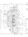
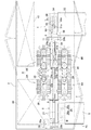
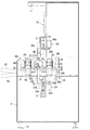
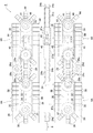
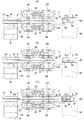
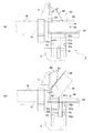
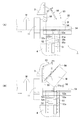
図1乃至図3は本発明の実施の形態に係るワーク切り離し装置1を組み込んだ単管連続自動溶接装置を示し、当該単管連続自動溶接装置は、ステンレス鋼板等の金属板材を円筒状に曲げ加工して成る複数のワークWをそのスリット部Waが夫々真上を向くように配置し、各ワークWを直列状に連ねた状態で軸線方向へ搬送しつつ各ワークWのスリット部Waを順次突合せ溶接して円筒状の単管を連続的に製造するものであり、フレーム材及びパネル材等から成るキャビネット本体2に、上部プレート3、下部プレート4、ワーク搬入装置5、ワーク位置決め装置6、ワーク挿入装置7、ワーク搬送装置8、センターガイド9、溶接装置10及びワーク切り離し装置1等を配設したものである。
尚、図1及び図3に於いて、11はワーク保持具、12は制御盤、13はレベリングパット、14は自在キャスター、15は冷却器、16は自動給水装置、17は作業灯、18は主操作パネルである。
Hereinafter, embodiments of the present invention will be described in detail with reference to the drawings.
1 to 3 show a single pipe continuous automatic welding apparatus incorporating a
In FIGS. 1 and 3, 11 is a work holder, 12 is a control panel, 13 is a leveling pad, 14 is a free caster, 15 is a cooler, 16 is an automatic water supply device, 17 is a work lamp, and 18 is a work light. This is the main operation panel.
前記上部プレート3は、図1及び図3に示す如く、キャビネット本体2に設けたガイドレール19に鉛直姿勢の状態で昇降自在に支持されており、モータ20a、ベルト伝動機構20b及びネジ機構20cから成る駆動装置20により昇降動し、ワークWの直径に応じて高さ調整自在となっている。この上部プレート3には、センターガイド9、上部ガイド機構21、溶接装置10、ワーク継ぎ目検出レーザーセンサー(図示省略)及びワーク有無検出光センサー(図示省略)等が配設されている。
又、下部プレート4は、図1及び図3に示す如く、上部プレート3の下方位置で且つキャビネット本体2に設けたガイドレール22に鉛直姿勢の状態で昇降自在に支持されており、モータ23a、ベルト伝動機構23b及びネジ機構23cから成る駆動装置23により昇降動し、ワークWの直径に応じて高さ調整自在となっている。この下部プレート4には、ワーク位置決め装置6、ワーク挿入装置7、下部ガイド機構24、ワーク継ぎ目検出レーザーセンサー(図示省略)及びワーク切り離し装置1等が配設されている。
As shown in FIGS. 1 and 3, the
Further, as shown in FIGS. 1 and 3, the
前記ワーク搬入装置5は、ベンディング機(図示省略)等により円筒状に曲げ加工された金属板製のワークWをワーク位置決め装置6の回転ローラ27上に順次搬入するものであり、図1及び図2に示す如く、複数本のワークWを並列状態でストックする傾斜状の搬入シュート25と、搬入シュート25上のワークWを一つずつ持ち上げてワーク位置決め装置6の回転ローラ27へ受け渡す流体圧シリンダ26a及び昇降枠26bから成るワークリフター26とから構成されており、ワークリフター26の流体圧シリンダ26aが伸縮動作を繰り返すことによって、搬入シュート25上にストックされているワークWをワーク位置決め装置6の回転ローラ27へ順次搬入することができるようになっている。
The workpiece carry-in
前記ワーク位置決め装置6は、ワーク搬入装置5により搬入されたワークWを受け取ってそのスリット部Waを一定位置に揃えるものであり、図1及び図2に示す如く、ワークリフター26からワークWを受け取る水平な一対の回転ローラ27と、回転ローラ27を回転制御するモータ28a及び伝動機構28bから成る駆動部28と、回転ローラ27に支持されたワークWのスリット部Waを検出する光電管等のセンサー(図示省略)等から成り、回転ローラ27に支持されているワークWのスリット部Waが真上を向くようにセンサーからの検出信号に基づいて駆動部28により回転ローラ27の回転を駆動制御するように構成されている。
The
前記ワーク挿入装置7は、ワーク位置決め装置6によりスリット部Waが真上を向く状態に揃えられたワークWを軸線方向へ移送して後述するワーク搬送装置8に送り込むものであり、図2に示す如く、回転ローラ27上に支持されたワークWの端面に当接自在なプッシャー及びこれをワークWの軸線方向へ往復移動させる流体圧シリンダ(図示省略)とから成り、プッシャーをワークWの端面に押し当て、この状態で流体圧シリンダを作動させてワークWを軸線方向へ移送することによって、回転ローラ27上のワークWをワーク搬送装置8へ送り込むことができるようになっている。
The
前記ワーク搬送装置8は、ワーク挿入装置7からワークWを受け取って直列状に連ねた状態で軸線方向へ搬送すると共に、ワークWを外側から挾持してそのスリット部Waを突き合せるものであり、ワークWの直径に関係なくワークWを確実且つ良好に保持して真円の状態で搬送し、且つワークW間の隙間及びワークWの軸方向のズレを修正しながら各ワークWを軸線方向へ連続的に搬送できるように構成されている。
The
即ち、ワーク搬送装置8は、図1乃至図3に示す如く、ワーク挿入装置7からワークWを受け取ってこれを両側から挾持しながら搬送する一対のキャタピラ式コンベヤ8Aから成るワーク送り部と、ワーク送り部からワークWを受け取ってこれを両側から挾持してワークWのスリット部Waを突き合せた状態で搬送する一対のキャタピラ式コンベヤ8Bから成るワーク溶接送り部と、ワーク送り部のキャタピラ式コンベヤ8Aとワーク溶接送り部のキャタピラ式コンベヤ8Bとを連動連結して両キャタピラ式コンベヤ8A,8Bの搬送速度を変える伝動機構29と、搬送中のワークWの上面側を保持しながら案内する上部ガイド機構21と、搬送中のワークWの下面側を保持しながら案内する下部ガイド機構24とを備えており、ワークWの外周面を前記両キャタピラ式コンベヤ8A,8B、上部ガイド機構21及び下部ガイド機構24により左右上下方向から保持してワークWを真円の状態で搬送すると共に、ワーク送り部のワークWの送り速度をワーク溶接送り部のワークWの搬送速度よりも速い速度に設定し、先行するワークWの後端面に後続のワークWの先端面を密着させ、ワークW間の隙間及びワークWの軸方向のズレを修正しながら各ワークWを軸線方向へ連続的に搬送できるように構成されている。
又、ワーク送り部及びワーク溶接送り部の各一対のキャタピラ式コンベヤ8A,8Bは、ワークWの側方位置にワークWと直交する水平方向へ移動調整可能に配設した水平プレート30上に夫々配設されており、水平プレート30を移動調整して各一対のキャタピラ式コンベヤ8A,8B間の間隔を可変調整することによって、ワークWの直径に関係なくワークWを両側から確実且つ良好に挾持することができるようになっている。
尚、各キャタピラ式コンベヤ8A,8Bを支持する水平プレート30は、キャビネット本体2に設けたワークWの軸線と直交する水平姿勢のガイドレール31に移動自在に支持されており、モータ32a、ベルト伝動機構32b及びネジ機構32cから成る駆動装置32より水平移動するようになっている。
That is, as shown in FIGS. 1 to 3, the
Further, the pair of
The
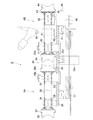
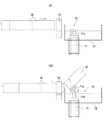
前記ワーク送り部の一対のキャタピラ式コンベヤ8Aは、図4及び図5に示す如く、水平プレート30に一定の間隔を空けて水平回転自在に支持された駆動スプロケット33及び従動スプロケット34と、両スプロケット33,34に巻き回された無端状のチェーン35と、チェーン35のワークWに対向する部分を一定位置に保持するガイドブロック36と、チェーン35に保持板37を介して一定間隔毎に取り付けられ、ワークWの側面を保持する複数のブロック状の保持部材38等から夫々構成されている。
又、ワーク送り部の各保持部材38は、ワークWに当接する面が断面形状横向きのU字状に形成されており、ワークWの直径に関係なくワークWの側面を確実且つ良好に保持できるようになっている。これらの保持部材38は、ワークWを次々とワーク溶接送り部へ送り込ませるため、一定の粘りと滑り機能を有するクロロプレンゴムにより形成されている。
As shown in FIGS. 4 and 5, the pair of
In addition, each holding
一方、ワーク溶接送り部の一対のキャタピラ式コンベヤ8Bは、図4及び図5に示す如く、水平プレート30に一定の間隔を空けて水平回転自在に支持された駆動スプロケット39及び従動スプロケット40と、両スプロケット39,40に巻き回された無端状のチェーン41と、チェーン41のワークWに対向する部分を一定位置に保持するガイドブロック42と、チェーン41に保持板43を介して一定間隔毎に取り付けられ、ワークWの側面を保持する複数のブロック状の保持部材44と、駆動スプロケット39を回転駆動するサーボモータ45等から夫々構成されており、両キャタピラ式コンベヤ8Bの下流側下方位置に夫々配置したフォトセンサー46により最も下流側に位置する保持板43を検出し、両方のキャタピラ式コンベヤ8Bの位相がずれたときに夫々のサーボモータ45を制御して両方のキャタピラ式コンベヤ8Bの速度を補正し、両方のキャタピラ式コンベヤ8Bの位相が同じになるように駆動制御されている。これにより、ワーク溶接送り部の一対のキャタピラ式コンベヤ8Bに挾持された状態で搬送されているワークWが軸線方向へずれるのを防止することができる。
又、ワーク溶接送り部の各保持部材44は、ワークWに当接する面が断面形状横向きのU字状に形成されており、ワークWの直径に関係なくワークWの側面を確実且つ良好に保持できるようになっている。これらの保持部材44は、ワークW両側面に一定の加圧力を加えながらワークWを一定の速度で搬送させるため、ワーク送り部の保持部材38よりも硬さが必要になり、そのために硬さと耐久性に優れたウレタンゴムにより形成されている。
On the other hand, as shown in FIGS. 4 and 5, the pair of
In addition, each holding
前記伝動機構29は、ワーク送り部のキャタピラ式コンベヤ8Aの速度がワーク溶接送り部のキャタピラ式コンベヤ8Bの速度よりも速い速度になるように両キャタピラ式コンベヤ8A,8Bを連動連結するものであり、図4及び図5に示す如く、ワーク溶接送り部の従動軸側に設けた大径スプロケット29aと、ワーク送り部の駆動軸側に設けた小径スプロケット29bと、両スプロケット29a,29bに巻き回された無端状のチェーン29cと、チェーン29cに噛み合うテンション用スプロケット29dとから構成されている。この実施の形態に於いては、伝動機構29は、ワーク送り部のキャタピラ式コンベヤ8Aの速度がワーク溶接送り部のキャタピラ式コンベヤ8Bの速度の1.6倍となるように設定されている。
従って、ワーク送り部及びワーク溶接送り部の各キャタピラ式コンベヤ8A,8BによりワークWを連続して搬送した場合、ワーク溶接送り部のキャタピラ式コンベヤ8Bにより搬送されている先行のワークWの後端面にワーク送り部のキャタピラ式コンベヤ8Aにより搬送される後続のワークWの先端面が当接して密着し、両ワークW間の隙間及びワークWの軸方向のズレを修正しながらワークWが連続的に搬送されることになる。
又、この伝動機構29には、先行するワークWの後端面に後続のワークWの先端面が密着して両ワークW間の隙間及びワークWの軸方向のズレが修正された後、伝動機構29に過負荷が掛かったときにトルクを遮断するトルクリミッタ(図示省略)が設けられている。これにより、ワークWがワーク送り部からワーク溶接送り部へ必要以上に送り込まれるのを防止することができる。
The
Therefore, when the workpiece W is continuously conveyed by the
The
前記上部ガイド機構21は、図1に示す如く、上部プレート3に固定したブラケット21dに設けられ、搬送されているワークWのスリット部Waの両側部分に当接する複数個の上部ガイドローラ21aと、上部プレート3に固定したブラケット21dに設けられ、溶接装置10のプラズマ溶接用トーチ49の上流側位置及び下流側位置に夫々位置して搬送されているワークWの上面側に摺動可能に当接する冷却機能を備えた角柱状の上流側押えヘラ21b及び下流側押えヘラ21cとから成り、上部プレート3を昇降動させることによって、ワークWの直径に応じて高さ調整できるようになっている。従って、上部ガイド機構21は、上部ガイドローラ21a及び各押えヘラ21b,21cをワークWの直径に関係なく、ワークWの上面側へ当接させることができ、ワークWの上面側を確実且つ良好に保持しながら案内することができる。
As shown in FIG. 1, the
前記下部ガイド機構24は、図1及び図2に示す如く、下部プレート4に固定したブラケット24bに設けられ、搬送されているワークWの下面側に当接する複数個の下部ガイドローラ24aから成り、下部プレート4を昇降動させることによって、ワークWの直径に応じて高さ調整できるようになっている。従って、下部ガイド機構24は、下部ガイドローラ24aをワークWの直径に関係なく、ワークWの下面側へ当接させることができ、ワークWを確実に且つ良好に保持しながら案内することができる。
As shown in FIGS. 1 and 2, the
尚、ワーク送り部のキャタピラ式コンベヤ8Aとワーク溶接送り部のキャタピラ式コンベヤ8Bとの間には、図示していないがワーク送り部からワーク溶接送り部へ送り込まれるワークWの両側面を保持しながら案内する複数の側面ガイドローラが設けられており、短いワークWであっても、ワーク送り部からワーク溶接送り部へのワークWの送り込みを良好且つ確実に行えるように工夫されている。
Although not shown, both side surfaces of the workpiece W fed from the workpiece feeding portion to the workpiece welding feeding portion are held between the
前記センターガイド9は、ワーク送り部の上流側に位置して上部プレート3に鉛直姿勢で取り付けられ、上部プレート3の昇降動により高さ調整可能となっており、ワーク挿入装置7によりワーク送り部の一対のキャタピラ式コンベヤ8A間へ押し込まれるワークWのスリット部Waに挿入されてワークWの心出しを行うと共に、ワークWをそのスリット部Waが真上を向く姿勢で案内するものである。
このセンターガイド9は、ワークWのスリット部Waの幅よりも若干薄い厚みを有する金属製の板材により形成されており、その内部には溶接装置10の溶接治具47(下部治具47b)へアルゴンガス等のシールドガスを供給するガス通路(図示省略)と冷却水を供給する冷却水通路(図示省略)とが夫々形成されている。
The
The
前記溶接装置10は、ワーク溶接送り部の一対のキャタピラ式コンベヤ8B間に配設されており、各ワークWの突き合されたスリット部Waを順次突合せ溶接するものである。この溶接装置10には、プラズマ溶接法と溶接治具47とを組み合せて成る溶接装置10が使用されている。
即ち、溶接装置10は、溶接電源48と、上部プレート3に取り付けられ、タングステン電極棒及び水冷構造のノズルを備えたプラズマ溶接用トーチ49と、プラズマ溶接用トーチ49の近傍位置に配設され、上部プレート3の昇降動により高さ調整される溶接治具47と、上部プレート3に取り付けられ、溶接状況(タングステン電極棒の消耗やアークの状態等)を確認する監視カメラ50等から構成されており、ワークWの突き合されたスリット部Waを溶接する際にプラズマ溶接用トーチ49及び溶接治具47が上部プレート3の昇降動により自動的に高さ調整されて溶接位置を取り得るようになっている。
又、溶接治具47は、ワークWの接合部にアークエネルギーを集中的に与え、且つ溶接後の余分な熱をワークWより素早く吸収してワークWの熱歪を最小限に抑えるためのものであり、プラズマ溶接用トーチ49の先端部両側に位置して下流側押えヘラ21cに水平姿勢で取り付けられ、主にアークの拡がりを遮断してワークWの接合部にエネルギーを集中させるための銅材製の上部治具47aと、センターガイド9の下端部に水平姿勢で取り付けられ、主に溶接後のワークWを素早く冷却するための銅材製の下部治具47b(センターガイド9のガス通路に連通してシールドガスが流れるガス通路と、センターガイド9の冷却水通路に連通して冷却水が流れる冷却水通路とが夫々形成されている)とから構成されている。この溶接治具47を用いることによって、ビード溶け落ちや穴あきの発生、溶接熱影響部の粗粒化を夫々防止することができる。
The
That is, the
The
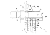
そして、本発明の実施の形態に係るワーク切り離し装置1は、ワーク搬送装置8の下流側位置に配設されており、溶接により端部同士がビード部分で接合された状態で搬送されて来た複数のワークWを夫々単一のワークWに切り離すものである。
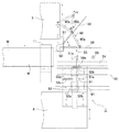
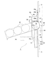
即ち、ワーク切り離し装置1は、図1及び図2に示す如く、接合状態で搬送されて来るワークWの下方位置に配設され、先頭に位置するワークWを上方へ突き上げてその端部接合部を支点にして上方へ折り曲げる鉛直姿勢の突き上げシリンダ51と、突き上げシリンダ51をワークWの搬送方向へ往復移動自在に支持するシリンダ支持機構52と、接合状態で搬送されて来るワークWの上方位置に配設され、先頭に位置するワークWの突き上げ時にワークWを上方から保持すると共に、端部接合部を支点にして上方へ折り曲げられたワークWをその姿勢を保持しながら下方へ折り曲げるワーク押え装置53と、搬送されて来るワークWと突き上げシリンダ51との間に配置され、突き上げシリンダ51のロッド51aが通過できる開口54aを有すると共に、切り離されたワークWを受け止めて同じ方向へ転がすボックス形状のガイド体54と、ガイド体54の近傍位置に傾斜姿勢で配設され、切り離されたワークWをガイド体54から受け取って搬出する搬出シュート55と、先頭に位置するワークWの先端位置を検出する光センサー56とを備えており、光センサー56が先頭に位置するワークWの先端位置を検出すると、突き上げシリンダ51が数回駆動制御されると共に、ワーク押え装置53が作動するように構成されている。
And the workpiece | work cutting
That is, as shown in FIGS. 1 and 2, the
具体的には、突き上げシリンダ51は、図7に示す如く、ワークWを突き上げるロッド51aの先端部(ワークWに当接する部分)がワークWを突き上げたときにワークWの外周面を損傷させたり、変形させたりしないように円弧状の曲面に形成されており、後述するシリンダ支持機構52によりワークWの搬送方向へ往復移動自在に支持されている。
Specifically, as shown in FIG. 7, the push-up
シリンダ支持機構52は、図7及び図8に示す如く、下部プレート4に固定した支持板61にワークWの搬送方向に沿って配設された一対のガイドレール52aと、各ガイドレール52aにボールやコロ等の転動体(図示省略)を介してワークWの搬送方向へスライド自在に支持され、突き上げシリンダ51を鉛直姿勢で固定支持するスライダ52bと、支持板61と突き上げシリンダ51との間(又は支持板61とスライダ52bとの間)に介設され、ワークWの搬送方向へ移動した突き上げシリンダ51を元の位置に復帰させるスプリング52c(引張りスプリング)とから構成されており、突き上げシリンダ51によるワークWの突き上げ時に突き上げシリンダ51が連続的に送られて来るワークWに押されると、突き上げシリンダ51がスライダ52bと一緒にガイドレール52aに沿ってワークWの搬送方向へ水平移動し、又、ワークWによる押圧状態が解除されると、突き上げシリンダ51がスプリング52cの弾性力によりスライダ52bと一緒にワークWの搬送方向と反対方向へ水平移動して元の位置へ自動復帰するように構成されている。
As shown in FIGS. 7 and 8, the
ワーク押え装置53は、図7乃至図9に示す如く、上部プレート3に固定したブラケット57に上下方向へ揺動自在に支持され、先頭に位置するワークWの接合されたスリット部Waの両側位置に当接してワークWの姿勢を保持する二股状の押え板58と、ワークWの突き上げ時に押え板58を水平位置と傾斜位置とに亘って上下方向へ揺動させるロータリアクチュエータ59と、押え板58の下死点位置となる水平位置を規制してロータリアクチュエータ59に掛かる負荷を軽減する押え板58の位置規制機構60とを備えており、突き上げシリンダ51によるワークWの突き上げ時に押え板58がロータリアクチュエータ59によりワークWに当接した状態で水平位置から傾斜位置へ揺動して端部接合部を支点にして上方へ折り曲げられるワークWの姿勢を保持し、又、押え板58がロータリアクチュエータ59により上方へ折り曲げられたワークWに当接した状態で傾斜位置から水平位置へ揺動してワークWをその姿勢を保持しながら下方へ折り曲げるように構成されている。
尚、ロータリアクチュエータ59には、従来公知の空気圧式ロータリアクチュエータや油圧式ロータリアクチュエータ、電動式ロータリアクチュエータ、ベーン形ロータリアクチュエータ等が使用されている。
又、押え板58の位置規制機構60は、図1に示す如く、上部プレート3と押え板58との間に折り畳み自在に設けた一対のリンク60aと、一方のリンク60aに移動調整可能に取り付けられ、押え板58が水平位置になったときに他方のリンク60a端面に当接してリンク60aの回動を規制するストッパー60b(ボルト)とから成り、ストッパー60bの先端がリンク60a端面に当接したときに押え板58が水平位置(下死点位置)で止まるように設定されている。この位置規制機構60を設けることによって、ロータリアクチュエータ59に掛かる負荷が軽減され、ロータリアクチュエータ59の延命を図れる。
As shown in FIGS. 7 to 9, the
As the
Further, as shown in FIG. 1, the
ガイド体54は、その上面が搬出シュート55側へ向かって下り傾斜状に形成されていると共に、下面が開放されたボックス形状を呈しており、接合状態で搬送されて来るワークWと突き上げシリンダ51との間に配置され、下部プレート4に支持板61を介して水平姿勢で取り付けられている。このガイド体54の上面には、突き上げシリンダ51の伸長動作時にそのロッドが通過できる長穴形状の開口54aが形成されている。
The upper surface of the
尚、上述した単管連続自動溶接装置に於いては、溶接の熱歪が溜まってくるワークWの境界部分及びワークWの溶接終了部分を突合せ溶接する際に電流値及びワークWの搬送速度を調整してワークWの端部の溶け落ちを防止するようにしている。
即ち、隣接するワークWの境界部分を突合せ溶接する際には、ワークWの境界に近づくに従って電流値を下げてワークWの搬送速度を遅くすると共に、ワークWの境界を通過した後に電流値を元の値まで上げてワークWの搬送速度を元の速度に戻し、溶接を出来る限り小さい熱エネルギーで行うことにより、ワークWの端部の溶け落ちを解消するようにしている。
又、ワークWの溶接終了部分を突合せ溶接する際には、ワークWの終端に近づくに従って電流値を下げてワークWの搬送速度を遅くし、溶接を出来る限り小さい熱エネルギーで行うことにより、ワークWの端部の溶け落ちを解消するようにしている。
In the single pipe continuous automatic welding apparatus described above, the current value and the workpiece W conveyance speed are set when butt welding the boundary portion of the workpiece W where welding thermal strain accumulates and the welding end portion of the workpiece W. Adjustment is made to prevent the end of the workpiece W from being melted.
That is, when butt-welding the boundary part between adjacent workpieces W, the current value is lowered to approach the boundary of the workpiece W to reduce the conveyance speed of the workpiece W, and the current value is set after passing through the boundary of the workpiece W. By raising the workpiece W to the original value and returning the conveying speed of the workpiece W to the original velocity and performing welding with as little heat energy as possible, melting of the end portion of the workpiece W is eliminated.
In addition, when butt welding the welded end portion of the workpiece W, the current value is lowered as the end of the workpiece W is approached, the conveyance speed of the workpiece W is reduced, and welding is performed with as little heat energy as possible. The melting of the end of W is eliminated.
次に、上述した単管連続自動溶接装置を用いて円筒状に曲げ加工された複数のワークWから単管を連続的に製造する場合について説明する。
尚、ワークWには、板厚1.5mm又は2.0mm、外径88mm〜121mm、長さ84mm〜300mmのステンレス鋼板製の円筒状のワークWが使用されている。又、溶接電流、アーク長さ、ワークWの搬送速度、不活性ガスの供給量、タングステン電極棒の先端形状等の溶接条件は、ワークWの材質、板厚等に応じて最適の条件下に設定されていることは勿論である。
Next, the case where a single pipe is continuously manufactured from a plurality of workpieces W bent into a cylindrical shape using the single pipe continuous automatic welding apparatus described above will be described.
The workpiece W is a cylindrical workpiece W made of a stainless steel plate having a thickness of 1.5 mm or 2.0 mm, an outer diameter of 88 mm to 121 mm, and a length of 84 mm to 300 mm. Welding conditions such as welding current, arc length, workpiece W conveyance speed, inert gas supply amount, tip shape of tungsten electrode rod, etc. are under optimum conditions according to the workpiece W material, plate thickness, etc. Of course, it is set.
複数のワークWから単管を連続的に製造する場合、先ず、ワークWの直径に応じてワーク送り部及びワーク溶接送り部の各一対のキャタピラ式コンベヤ8A,8Bの間隔と、上部ガイド機構21の上部ガイドローラ21a、上流側押えヘラ21b及び下流側押えヘラ21cの高さ位置と、下部ガイド機構24の下部ガイドローラ24aの高さ位置を夫々調整し、ワークWの外周面を各一対のキャタピラ式コンベヤ8A,8B、上部ガイドローラ21a及び下部ガイドローラ24a等により左右上下方向から一定の力(ワークWが真円の状態に保持されて変形されない程度の力)で保持できるようにする。このとき、上部プレート3の昇降動により上部治具47a及び下部治具47bの高さ位置も、ワークWの直径に応じて最適な位置に調整される。又、ワーク切り離し装置1の押え板58、突き上げシリンダ51及びガイド体54等の高さ位置も、上部プレート3及び下部プレート4の昇降動によりワークWの直径に応じて最適な位置に調整される。
When a single pipe is continuously manufactured from a plurality of workpieces W, first, according to the diameter of the workpiece W, the distance between each pair of
次に、作業員が手動操作により複数のワークWをそのスリット部Waがセンターガイド9に入り込むようにしてワーク送り部の一対のキャタピラ式コンベヤ8A間に順次挿入し、ワークWの外周面を一対のキャタピラ式コンベヤ8A、上部ガイドローラ21a及び下部ガイドローラ24aにより左右上下方向から保持させると共に、先頭に位置するワークWをその先端が溶接装置10のプラズマ溶接用トーチ49の近傍位置に達するまで軸線方向へ移動させる(図6(A)参照)。このとき、先頭に位置するワークWのスリット部Waの先端部側は、ワーク溶接送り部の一対のキャタピラ式コンベヤ8Bの押圧作用により突き合された状態となっている。
尚、円筒状に曲げ加工された各ワークWは、両端部が軸線方向にズレている場合がある。この場合には、作業員が最初にワーク送り部の一対のキャタピラ式コンベヤ8A間に挿入するワークWと二番目に挿入するワークWのズレを手作業により修正した後、これらを一対のキャタピラ式コンベヤ8A間に挿入する。
Next, the operator manually inserts a plurality of workpieces W between the pair of
In addition, as for each workpiece | work W bent into the cylindrical shape, both ends may have shifted | deviated to the axial direction. In this case, after the operator manually corrects the deviation between the workpiece W inserted between the pair of
そして、上述した状態で単管連続自動溶接装置の自動運転を行う。そうすると、ワーク搬送装置8が作動してワークWを左右上下方向から保持して真円の状態で軸線方向へ移送すると共に、溶接装置10が作動して先頭に位置するワークWの突き合されたスリット部Waをプラズマ溶接用トーチ49の直下位置に於いて自動溶接して行く(図6(B)参照)。先頭に位置するワークWのスリット部Waが突合せ溶接されたら、引き続き二番目に位置するワークWがワーク搬送装置8により左右上下方向から保持されて真円の状態で軸線方向へ移送され、溶接装置10によりワークWの突き合されたスリット部Waが自動溶接されて行く。
Then, the single-tube continuous automatic welding apparatus is automatically operated in the state described above. Then, the
このようにして、ワークWがワーク搬送装置8により直列状に連なった状態で搬送されてそのスリット部Waが溶接装置10により順次突合せ溶接されて行くと、ワーク搬入装置5の搬入シュート25にストックされているワークWがワークリフター26の作動によって一本宛ワーク位置決め装置6の回転ローラ27上に受け渡されると共に、ワーク位置決め装置6によりそのスリット部Waを真上に向けた状態で位置決めされる(図6(C)参照)。
In this way, when the workpiece W is conveyed in a state of being connected in series by the
その後、ワーク挿入装置7の流体圧シリンダ(図示省略)が作動してプッシャーにより回転ローラ27上のワークWが軸線方向へ押し出されて行く。そうすると、ワークWは、そのスリット部Waがセンターガイド9へ挿入されると共に、ワーク送り部の一対のキャタピラ式コンベヤ8A間に挿入され、当該キャタピラ式コンベヤ8Aによりワーク溶接送り部側へ搬送された後、ワーク送り部の一対のキャタピラ式コンベヤ8Aの下流側端部からワーク溶接送り部の一対のキャタピラ式コンベヤ8B間に送り込まれ、当該キャタピラ式コンベヤ8Bにより溶接装置10側へ搬送されて行く。
このとき、ワーク送り部のキャタピラ式コンベヤ8AのワークWの搬送速度がワーク溶接送り部のキャタピラ式コンベヤ8BのワークWの搬送速度よりも速いため、ワーク溶接送り部のキャタピラ式コンベヤ8Bにより搬送されている先行のワークWの後端面にワーク送り部のキャタピラ式コンベヤ8Aにより搬送される後続のワークWの先端面が当接して密着し、両ワークW間の隙間及びワークWの軸線方向のズレを修正しながら各ワークWを連続的に搬送することになる。又、ワーク送り部の一対のキャタピラ式コンベヤ8Aとワーク溶接送り部の一対のキャタピラ式コンベヤ8Bとの間にトルクリミッタ付きの伝動機構29を介設しているため、先行するワークWの後端面に後続のワークWの先端面が密着して両ワークW間の隙間及びワークWの軸方向のズレが修正された後、伝動機構29に過負荷が掛かると、トルクが遮断されてワーク送り部のキャタピラ式コンベヤ8Aが停止するようになっている。その結果、ワークWがワーク送り部からワーク溶接送り部へ必要以上に送込まれると云うことがなく、ワーク溶接送り部に送り込まれたワークWは一定の速度で搬送されることになり、溶接速度が変化すると云うことがない。
Thereafter, a fluid pressure cylinder (not shown) of the
At this time, since the conveyance speed of the workpiece W of the
そして、ワーク溶接送り部の一対のキャタピラ式コンベヤ8B間に送り込まれたワークWは、キャタピラ式コンベヤ8Bにより直列状に連なった状態で軸線方向へ搬送されると共に、溶接装置10のプラズマ溶接用トーチ49の直下位置に於いて突き合されているスリット部Waが順次突合せ溶接されて行く。
このとき、ワークWは、一対のキャタピラ式コンベヤ8B、上部ガイドローラ21a及び下部ガイドローラ24aにより上下左右方から保持されて真円の状態で搬送されていると共に、ワークWのスリット部Waに上流側押えヘラ21bが当接してスリット部Waの段付きを無くした状態で搬送され、然も、ゴム部材製の保持部材44を備えたキャタピラ式コンベヤ8Bにより搬送されているため、スリップすることなく安定した姿勢で且つ一定の速度で溶接装置10側へ移送されることになる。即ち、ワークWは、最適な状態で溶接装置10側へ移送されることになり、溶接装置10に於いて精度の高い溶接が行われることになる。
又、ワークWの境界部分を突合せ溶接する際には、電流値及びワークWの搬送速度を調整して突合せ溶接を出来る限り小さい熱エネルギーで行うようにしているため、ワークWの端部の溶け落ちが防止されることになる。
And the workpiece | work W sent between the pair of
At this time, the work W is held from above, below, left, and right by a pair of
In addition, when butt welding the boundary portion of the workpiece W, the current value and the conveyance speed of the workpiece W are adjusted so that butt welding is performed with as little heat energy as possible. Falling will be prevented.
溶接装置10により突合せ溶接されたワークWは、ワーク搬送装置8のワーク溶接送り部から順次送り出されてワーク保持具11を通過した後、先頭に位置するワークWがワーク切り離し装置1によって端部接合部で切り離される。
即ち、先頭に位置するワークWの先端が光センサー56により検出されると、ロータリアクチュエータ59が突き上げシリンダ51よりも先に作動して傾斜位置にある押え板58を水平位置へ降ろしてワークWの頂部を押え板58で保持すると共に、引き続きこの状態で突き上げシリンダ51が伸長動作してワークWを突き上げてその端部接合部を支点にして上方へ折り曲げる(図10(A)及び(B)参照)。その後、突き上げシリンダ51が短縮動作すると共に、押え板58がロータリアクチュエータ59により傾斜位置から水平位置へ揺動し、ワークWを保持しながらその端部接合部を支点にして強制的に下方へ折り曲げる(図11(A)及び(B)参照)。以下、同様にして突き上げシリンダ51が数回作動すると共に、突き上げシリンダ51の伸縮動作に伴って押え板58もロータリアクチュエータ59により上下方向へ数回揺動する。その結果、先頭に位置するワークWの端部接合部に衝撃が与えられることになり、ワークWはその端部接合部で切り離されることになる(図12参照)。
The workpiece W butt-welded by the
That is, when the front end of the workpiece W positioned at the head is detected by the
ところで、突き上げシリンダ51によるワークWの突き上げ時にはワークWがワーク搬送装置8により連続的に前方へ搬送されて来るため、突き上げシリンダ51が順次送られて来るワークWによりワークWの搬送方向へ強く押圧されることになる。
しかし、このワーク切り離し装置1によれば、突き上げシリンダ51をシリンダ支持機構52によりワークWの搬送方向へ往復移動自在に支持し、ワークWの突き上げ時に突き上げシリンダ51が連続的に送られて来るワークWに押されてその搬送方向へ移動するようにしているため、例え突き上げシリンダ51が順次搬送されて来るワークWに押されても、上方へ突き上げられたワークWの端部接合部(支点)と突き上げシリンダのワークWに当接している部分(作用点)とに大きな力が発生すると云うことがなく、突き上げシリンダ51のロッド51aは円滑且つスムースに下降することになる。その結果、ワークWの搬送が突き上げシリンダ51によって妨げられたりすると云うことがなく、ワークWの端部の変形を防止することができると共に、装置自体の運転を停止したりする必要もなくなる。
又、このワーク切り離し装置1は、押え板58がロータリアクチュエータ59により突き上げシリンダ51の伸縮動作に同期して揺動し、ワークWの突き上げ時にワークWを上方から保持すると共に、上方へ折り曲げられたワークWをその姿勢を保持しながら下方へ折り曲げるようにしているため、切り離されたワークWが色々な方向へ飛んで行くと云うことがなく、ワークWを整然とした一定の姿勢でもって搬出するとことができる。然も、押え板58を二股状に形成してワークWの接合されたスリット部Waの両側位置に当接させているため、ワークWの直径に関係なくワークWを確実且つ良好に保持することできる。
更に、このワーク切り離し装置1は、上方へ折り曲げられたワークWを押え板58により下方へ強制的に折り曲げるようにしているため、長さが短い軽量のワークWであっても、上方へ折り曲げられたワークWを下方へ確実に折り曲げることができ、引き続き突き上げシリンダ51による突き上げ作業を行えることになり、ワークWの切り離しを確実に行えることになる。
By the way, when the workpiece W is pushed up by the pushing
However, according to the
In the
Furthermore, since the
そして、先頭に位置するワークWが切り離されたら、引き続き送られて来る先頭に位置するワークWがワーク切り離し装置1により端部接合部で切り離される。切り離されたワークWは、順次ガイド板54の傾斜した上面へ載せられ、ガイド板54の上面を搬出シュート55側へ転がって行き、搬出シュート55から後続の加工機へ送られて行く。
And if the workpiece | work W located in the head is cut | disconnected, the workpiece | work W located in the head which will be sent continuously will be cut | disconnected by an edge part junction part by the workpiece | work cutting
1はワーク切り離し装置、51は突き上げシリンダ、52はシリンダ支持機構、52aはガイドレール、52bはスライダ、52cはスプリング、53はワーク押え装置、58は押え板、59はロータリアクチュエータ、60は押え板の位置規制機構、Wはワーク、Waはワークのスリット部。 1 is a workpiece separating device, 51 is a push-up cylinder, 52 is a cylinder support mechanism, 52a is a guide rail, 52b is a slider, 52c is a spring, 53 is a work pressing device, 58 is a pressing plate, 59 is a rotary actuator, and 60 is a pressing plate , W is a workpiece, Wa is a slit portion of the workpiece.
Claims (5)
Priority Applications (1)
| Application Number | Priority Date | Filing Date | Title |
|---|---|---|---|
| JP2004121245A JP4475640B2 (en) | 2004-04-16 | 2004-04-16 | Work separation device |
Applications Claiming Priority (1)
| Application Number | Priority Date | Filing Date | Title |
|---|---|---|---|
| JP2004121245A JP4475640B2 (en) | 2004-04-16 | 2004-04-16 | Work separation device |
Publications (2)
| Publication Number | Publication Date |
|---|---|
| JP2005297056A true JP2005297056A (en) | 2005-10-27 |
| JP4475640B2 JP4475640B2 (en) | 2010-06-09 |
Family
ID=35329233
Family Applications (1)
| Application Number | Title | Priority Date | Filing Date |
|---|---|---|---|
| JP2004121245A Expired - Fee Related JP4475640B2 (en) | 2004-04-16 | 2004-04-16 | Work separation device |
Country Status (1)
| Country | Link |
|---|---|
| JP (1) | JP4475640B2 (en) |
Cited By (3)
| Publication number | Priority date | Publication date | Assignee | Title |
|---|---|---|---|---|
| CN104128710A (en) * | 2014-07-03 | 2014-11-05 | 东莞亦准自动化科技有限公司 | Workpiece distributor |
| CN106736164A (en) * | 2016-12-30 | 2017-05-31 | 张家港科康智能科技有限公司 | A kind of Straight seam welding machine mandrel and retaining mechanism |
| CN110102597A (en) * | 2019-04-19 | 2019-08-09 | 无锡平舍智能科技有限公司 | A kind of preceding apparatus for shaping of metal plate edge rolling pipe weldering |
-
2004
- 2004-04-16 JP JP2004121245A patent/JP4475640B2/en not_active Expired - Fee Related
Cited By (4)
| Publication number | Priority date | Publication date | Assignee | Title |
|---|---|---|---|---|
| CN104128710A (en) * | 2014-07-03 | 2014-11-05 | 东莞亦准自动化科技有限公司 | Workpiece distributor |
| CN106736164A (en) * | 2016-12-30 | 2017-05-31 | 张家港科康智能科技有限公司 | A kind of Straight seam welding machine mandrel and retaining mechanism |
| CN110102597A (en) * | 2019-04-19 | 2019-08-09 | 无锡平舍智能科技有限公司 | A kind of preceding apparatus for shaping of metal plate edge rolling pipe weldering |
| CN110102597B (en) * | 2019-04-19 | 2023-12-15 | 无锡平舍智能科技有限公司 | Shaping device before metal plate coiled pipe welding |
Also Published As
| Publication number | Publication date |
|---|---|
| JP4475640B2 (en) | 2010-06-09 |
Similar Documents
| Publication | Publication Date | Title |
|---|---|---|
| KR101063085B1 (en) | Welding apparatus and process for joining metal sheet strips | |
| KR101333268B1 (en) | Roll forming apparatus for long-rail frame | |
| US12134149B2 (en) | Device for the orbital processing of non-rotating joints and pipe ends | |
| JP2010503541A5 (en) | ||
| WO1987005244A1 (en) | Method and device for cutting and welding steel belts | |
| JP3986979B2 (en) | Single pipe continuous automatic welding equipment | |
| JPS58188596A (en) | Continuous feeding welder for can body made of metal | |
| JP4475640B2 (en) | Work separation device | |
| US20190329314A1 (en) | Method and device for joining workpieces having at least two transport devices which can be controlled independently of each other to configure an offset between head ends and/or rear ends of the workpieces prior to joining | |
| JP4364603B2 (en) | Single pipe continuous automatic welding equipment | |
| JP2537312B2 (en) | Laser welding equipment | |
| US5749511A (en) | Method and apparatus for connecting two workpieces together | |
| JP6855065B2 (en) | Pipe welding equipment and pipe manufacturing equipment | |
| KR100371510B1 (en) | Method and device for transferring a hollow-section blank | |
| WO2020121946A1 (en) | Laser blanking device | |
| KR101523406B1 (en) | Metal sheet butt-welding method and device for a continuous manufacturing process | |
| CN116652441A (en) | Full-automatic welding machine for barrel body | |
| JP3999349B2 (en) | Spiral steel pipe forming equipment | |
| JPS6264487A (en) | Pre-working device for steel plate continuous processing equipment | |
| JP4275020B2 (en) | Welding material separator | |
| JP2000000688A (en) | Continuous welding method and continuous welding equipment for strip steel plate in longitudinal direction | |
| JP6980237B2 (en) | Fully automatic butt joining device | |
| JP2008178897A (en) | Welding apparatus installed on inlet side of steel strip continuous treating facility, and its welding method | |
| CN119388161A (en) | Square pile hoop production line | |
| JP2000084695A (en) | Continuous welding method of strip steel plate in longitudinal direction and welding equipment |
Legal Events
| Date | Code | Title | Description |
|---|---|---|---|
| A621 | Written request for application examination |
Free format text: JAPANESE INTERMEDIATE CODE: A621 Effective date: 20051108 |
|
| A977 | Report on retrieval |
Free format text: JAPANESE INTERMEDIATE CODE: A971007 Effective date: 20080212 |
|
| A131 | Notification of reasons for refusal |
Free format text: JAPANESE INTERMEDIATE CODE: A131 Effective date: 20080215 |
|
| A521 | Written amendment |
Free format text: JAPANESE INTERMEDIATE CODE: A523 Effective date: 20080325 |
|
| A131 | Notification of reasons for refusal |
Free format text: JAPANESE INTERMEDIATE CODE: A131 Effective date: 20090408 |
|
| A521 | Written amendment |
Free format text: JAPANESE INTERMEDIATE CODE: A523 Effective date: 20090421 |
|
| TRDD | Decision of grant or rejection written | ||
| A01 | Written decision to grant a patent or to grant a registration (utility model) |
Free format text: JAPANESE INTERMEDIATE CODE: A01 Effective date: 20100303 |
|
| A01 | Written decision to grant a patent or to grant a registration (utility model) |
Free format text: JAPANESE INTERMEDIATE CODE: A01 |
|
| A61 | First payment of annual fees (during grant procedure) |
Free format text: JAPANESE INTERMEDIATE CODE: A61 Effective date: 20100308 |
|
| R150 | Certificate of patent or registration of utility model |
Free format text: JAPANESE INTERMEDIATE CODE: R150 |
|
| FPAY | Renewal fee payment (event date is renewal date of database) |
Free format text: PAYMENT UNTIL: 20130319 Year of fee payment: 3 |
|
| FPAY | Renewal fee payment (event date is renewal date of database) |
Free format text: PAYMENT UNTIL: 20140319 Year of fee payment: 4 |
|
| R250 | Receipt of annual fees |
Free format text: JAPANESE INTERMEDIATE CODE: R250 |
|
| LAPS | Cancellation because of no payment of annual fees |