JP2005296982A - Forged product, forging device and forging method - Google Patents
Forged product, forging device and forging method Download PDFInfo
- Publication number
- JP2005296982A JP2005296982A JP2004114722A JP2004114722A JP2005296982A JP 2005296982 A JP2005296982 A JP 2005296982A JP 2004114722 A JP2004114722 A JP 2004114722A JP 2004114722 A JP2004114722 A JP 2004114722A JP 2005296982 A JP2005296982 A JP 2005296982A
- Authority
- JP
- Japan
- Prior art keywords
- mold
- metal body
- forging
- contact
- metal
- Prior art date
- Legal status (The legal status is an assumption and is not a legal conclusion. Google has not performed a legal analysis and makes no representation as to the accuracy of the status listed.)
- Granted
Links
- 238000005242 forging Methods 0.000 title claims abstract description 68
- 238000000034 method Methods 0.000 title claims abstract description 36
- 229910052751 metal Inorganic materials 0.000 claims abstract description 197
- 239000002184 metal Substances 0.000 claims abstract description 197
- 238000003780 insertion Methods 0.000 claims description 22
- 230000037431 insertion Effects 0.000 claims description 22
- 230000004308 accommodation Effects 0.000 claims description 21
- 238000003825 pressing Methods 0.000 claims description 14
- 230000002093 peripheral effect Effects 0.000 claims description 9
- 238000007670 refining Methods 0.000 claims description 5
- 239000000463 material Substances 0.000 claims 1
- 238000000465 moulding Methods 0.000 description 31
- 238000004519 manufacturing process Methods 0.000 description 8
- 230000015572 biosynthetic process Effects 0.000 description 5
- 238000010008 shearing Methods 0.000 description 3
- 230000000452 restraining effect Effects 0.000 description 2
- 229910000838 Al alloy Inorganic materials 0.000 description 1
- 238000005520 cutting process Methods 0.000 description 1
- 238000010586 diagram Methods 0.000 description 1
- 238000006073 displacement reaction Methods 0.000 description 1
- 230000000694 effects Effects 0.000 description 1
- 238000007730 finishing process Methods 0.000 description 1
- 239000010935 stainless steel Substances 0.000 description 1
- 229910001256 stainless steel alloy Inorganic materials 0.000 description 1
Images
Landscapes
- Forging (AREA)
Abstract
Description
本発明は、鍛造によって形成した鍛造成形品、及び鍛造装置、及び鍛造方法に関するものである。 The present invention relates to a forged product formed by forging, a forging device, and a forging method.
従来、釘、ボルト、ネジなどの係止用部材では、棒状に伸延した棒状部の一端に棒状部の径寸法よりも大きい寸法とした膨出形状の頭部を形成しており、このような係止用部材をステンレスやアルミニウム合金などの金属で形成する場合には、鍛造装置を用いた鍛造によって形成している。 Conventionally, locking members such as nails, bolts, screws, etc., have formed a bulge-shaped head that is larger than the diameter of the rod-shaped portion at one end of the rod-shaped portion extended into a rod shape. When the locking member is made of a metal such as stainless steel or aluminum alloy, it is formed by forging using a forging device.
すなわち、第1金型には係止用部材の棒状部となる金属体の棒状部分が挿入される挿入孔を設けており、この挿入孔に金属体の棒状部分を挿入しながらパンチである第2金型を第1金型に所定の圧力で押圧させて頭部の形成を行い、必要に応じて仕上げ処理を行って所定形状とした係止用部材を形成している(例えば、特許文献1参照。)。
しかしながら、上記した係止用部材では、使用時に棒状部と頭部との境界領域に大きな応力が作用することによって、係止用部材に破損が生じる場合には必ず棒状部と頭部との境界領域となっていた。 However, in the above-described locking member, when the locking member is damaged due to a large stress acting on the boundary region between the rod-shaped portion and the head at the time of use, the boundary between the rod-shaped portion and the head is always used. It was an area.
このような係止用部材の破損が生じないようにするために、通常は棒状部の径寸法が大きいものを使用することにより十分なマージンを得るようにしているが、係止用部材が使用されている製品の軽量化が要求されるのにともなって、係止用部材にも小型化・軽量化の要求が高まり、十分なマージンが得られ難くなっていた。 In order to prevent such a breakage of the locking member, a sufficient margin is usually obtained by using a rod having a large diameter, but the locking member is used. With the demand for lighter products, there has been a growing demand for smaller and lighter locking members, making it difficult to obtain a sufficient margin.
そこで、昨今では、係止用部材となる金属体の強度を向上させることによりマージンを得るようにしているが、強度を向上させた金属体は高コストとなるために市場に受け入れられにくいという問題があった。 Therefore, in recent years, a margin is obtained by improving the strength of the metal body serving as the locking member, but the problem is that the metal body with improved strength is not accepted by the market because of its high cost. was there.
このような現状に鑑み、金属組織を微細化することにより金属体の強度を向上させることができる手法を開発した本発明者らは、その手法を用いて係止用部材を形成することにより、低コストでマージンを向上させた係止用部材を形成する手法を開発し、本発明を成すに至ったものである。 In view of the current situation, the present inventors who developed a technique that can improve the strength of the metal body by refining the metal structure, by forming a locking member using the technique, A technique for forming a locking member with improved margin at low cost has been developed, and the present invention has been achieved.
本発明の鍛造成形品では、金属体を鍛造して形成した鍛造成形品において、強度を向上させる領域の金属体の金属組織を微細化して微細化領域を形成した。また、微細化領域は、金属体を第1の金型と第2の金型とで鍛造する場合に、第1の金型と第2の金型とが互いに当接する当接面に沿って、第1の金型と第2の金型との少なくともいずれか一方を他方に対して相対的に回転させて形成したことにも特徴を有するものである。 In the forged molded product of the present invention, in the forged molded product formed by forging the metal body, the microstructure of the metal body in the region where the strength is improved is refined to form a refined region. The miniaturized region is along the contact surface where the first mold and the second mold contact each other when the metal body is forged with the first mold and the second mold. Also, it is characterized in that it is formed by rotating at least one of the first mold and the second mold relative to the other.
また、本発明の鍛造装置では、第1の金型と第2の金型で金属体を所定形状に鍛造する鍛造装置において、第1の金型と第2の金型とを当接させるときに、第1の金型と第2の金型との当接面に沿って、第1の金型と第2の金型との少なくともいずれか一方を他方に対して相対的に回転させる回転手段を設けた。 Further, in the forging device of the present invention, when the first die and the second die are brought into contact with each other in the forging device forging the metal body into a predetermined shape with the first die and the second die. And a rotation for rotating at least one of the first mold and the second mold relative to the other along the contact surface between the first mold and the second mold. Means were provided.
また、本発明の鍛造装置では、第1の金型に設けた収容孔に頭部を突出させて金属体を挿入し、第1の金型に第2の金型を当接させて金属体を所定形状に鍛造する鍛造装置において、第1の金型と第2の金型とを当接させるときに、第1の金型と第2の金型との当接面に沿って第2の金型を回転させる回転手段を設けた。 Further, in the forging device of the present invention, the metal body is inserted with the head projecting into the accommodation hole provided in the first mold, and the second mold is brought into contact with the first mold to form the metal body. In the forging device forging the first mold and the second mold, when the first mold and the second mold are brought into contact with each other, the second along the contact surface between the first mold and the second mold. Rotating means for rotating the mold was provided.
さらに、以下の点にも特徴を有するものである。すなわち、
(1)第1の金型と第2の金型とを当接させるときに、収容孔に挿入された金属体を第2の金型の方向に押圧する押圧手段を設けたこと。
(2)第1の金型における第2の金型との当接面には、第2の金型の回転にともなって回転する回転板を設けたこと。
(3)回転板には金属体が挿通される金属体挿通孔を設けるとともに、この金属体挿通孔の内周面に金属体と当接させない非当接面を設けたこと。
Furthermore, the following points are also characteristic. That is,
(1) When the first mold and the second mold are brought into contact with each other, a pressing means for pressing the metal body inserted into the accommodation hole in the direction of the second mold is provided.
(2) A rotating plate that rotates with the rotation of the second mold is provided on the contact surface of the first mold with the second mold.
(3) The rotating plate is provided with a metal body insertion hole through which the metal body is inserted, and a non-contact surface that does not contact the metal body is provided on the inner peripheral surface of the metal body insertion hole.
また、本発明の鍛造方法では、第1の金型と第2の金型で金属体を所定形状に鍛造する鍛造方法において、第1の金型と第2の金型とを当接させたときに、第1の金型と第2の金型との当接面に沿って、第1の金型と第2の金型との少なくともいずれか一方を他方に対して相対的に回転させることとした。 In the forging method of the present invention, the first die and the second die are brought into contact with each other in the forging method in which the metal body is forged into a predetermined shape using the first die and the second die. Sometimes, at least one of the first mold and the second mold is rotated relative to the other along the contact surface between the first mold and the second mold. It was decided.
また、本発明の鍛造方法では、第1の金型に設けた収容孔に頭部を突出させて金属体を挿入し、第1の金型に第2の金型を当接させて金属体を所定形状に鍛造する鍛造方法において、第1の金型と第2の金型とを当接させたときに、第1の金型と第2の金型との当接面に沿って第2の金型を回転させることとした。 Further, in the forging method of the present invention, the metal body is inserted with the head projecting into the accommodation hole provided in the first mold, and the second mold is brought into contact with the first mold to form the metal body. In the forging method in which the first mold and the second mold are brought into contact with each other, the first and second molds are forged along the contact surface between the first mold and the second mold. The second mold was rotated.
さらに、以下の点にも特徴を有するものである。すなわち、
(1)第1の金型と第2の金型とを当接させるときに、収容孔に挿入された金属体を第2の金型の方向に押圧すること。
(2)第1の金型における第2の金型との当接面には回転板を設け、第2の金型の回転にともなって回転板を回転させること。
(3)回転板には金属体が挿通される金属体挿通孔を設けるとともに、この金属体挿通孔の内周面に金属体と当接させない非当接面を設けていること。
(4)第2の金型を回転させることにより捻回される金属体の領域をテーパ形状としていること。
Furthermore, the following points are also characteristic. That is,
(1) When the first mold and the second mold are brought into contact with each other, the metal body inserted into the accommodation hole is pressed in the direction of the second mold.
(2) A rotating plate is provided on the contact surface of the first mold with the second mold, and the rotating plate is rotated along with the rotation of the second mold.
(3) The rotating plate is provided with a metal body insertion hole through which the metal body is inserted, and a non-contact surface that does not contact the metal body is provided on the inner peripheral surface of the metal body insertion hole.
(4) The region of the metal body that is twisted by rotating the second mold is tapered.
請求項1記載の発明によれば、金属体を鍛造して形成した鍛造成形品において、強度を向上させる領域の金属体の金属組織を微細化して微細化領域を形成したことによって、鍛造成形品の全体の強度を向上させるのではなく、強度が必要な部分のみの強度を向上させることにより、低コストで鍛造成形品の強度向上を図ることができる。 According to the first aspect of the present invention, in the forged molded product formed by forging the metal body, the forged molded product is formed by refining the metal structure of the metal body in the region for improving the strength to form the refined region. The strength of the forged molded product can be improved at low cost by improving the strength of only the portion that requires strength, rather than improving the overall strength of the forged product.
請求項2記載の発明によれば、金属体を第1の金型と第2の金型とで鍛造する場合に、第1の金型と第2の金型とが互いに当接する当接面に沿って、第1の金型と第2の金型との少なくともいずれか一方を他方に対して相対的に回転させて微細化領域を形成することによって、極めて容易に微細化領域を形成することができ、製造コストを増大させることなく強度を向上させた鍛造成形品を製造できるので、低コストの鍛造成形品を提供できる。 According to invention of Claim 2, when a metal body is forged with a 1st metal mold | die and a 2nd metal mold | die, the contact surface which a 1st metal mold | die and a 2nd metal mold | die contact | abut mutually The micronized region can be formed very easily by rotating at least one of the first mold and the second metal mold relative to the other along the line. In addition, since a forged molded product with improved strength can be manufactured without increasing the manufacturing cost, a low-cost forged molded product can be provided.
請求項3記載の発明によれば、第1の金型と第2の金型で金属体を所定形状に鍛造する鍛造装置において、第1の金型と第2の金型とを当接させるときに、第1の金型と第2の金型との当接面に沿って、第1の金型と第2の金型との少なくともいずれか一方を他方に対して相対的に回転させる回転手段を設けたことにより、回転手段による回転にともなって金属体を捻回させることができ、捻回にともなう剪断歪みによって金属体の金属組織を微細化することができるので、捻回された部分だけ強度を向上させることができる。したがって、鍛造成形品の部分的な強度向上を図ることができ、製造コストを高騰させることなく鍛造成形品のマージンの向上を図ることができる。 According to the invention of claim 3, in the forging device forging the metal body into a predetermined shape with the first die and the second die, the first die and the second die are brought into contact with each other. Sometimes, at least one of the first mold and the second mold is rotated relative to the other along the contact surface between the first mold and the second mold. By providing the rotating means, the metal body can be twisted along with the rotation by the rotating means, and the metal structure of the metal body can be refined by shearing strain accompanying the twisting. Only the portion can improve the strength. Therefore, the partial strength of the forged product can be improved, and the margin of the forged product can be improved without increasing the manufacturing cost.
請求項4記載の発明によれば、第1の金型に設けた収容孔に頭部を突出させて金属体を挿入し、第1の金型に第2の金型を当接させて金属体を所定形状に鍛造する鍛造装置において、第1の金型と第2の金型とを当接させるときに、第1の金型と第2の金型との当接面に沿って第2の金型を回転させる回転手段を設けたことにより、回転手段による第2の金型の回転にともなって金属体を捻回させることができ、捻回にともなう剪断歪みによって金属体の金属組織を微細化することができるので、捻回された部分だけ強度を向上させることができる。したがって、鍛造成形品の部分的な強度向上を図ることができ、製造コストを高騰させることなく鍛造成形品のマージンの向上を図ることができる。 According to the fourth aspect of the present invention, the metal body is inserted with the head projecting into the accommodation hole provided in the first mold, and the second mold is brought into contact with the first mold to form the metal. In a forging device for forging a body into a predetermined shape, when the first mold and the second mold are brought into contact with each other, the first mold is formed along the contact surface between the first mold and the second mold. By providing the rotating means for rotating the second mold, the metal body can be twisted with the rotation of the second mold by the rotating means, and the metal structure of the metal body by shear strain accompanying the twisting. Therefore, it is possible to improve the strength of only the twisted portion. Therefore, the partial strength of the forged product can be improved, and the margin of the forged product can be improved without increasing the manufacturing cost.
請求項5記載の発明によれば、請求項4記載の鍛造装置において、第1の金型と第2の金型とを当接させるときに、収容孔に挿入された金属体を第2の金型の方向に押圧する押圧手段を設けたことによって、回転手段による第2の金型の回転によって金属体を捻回させる際に金属体の捻回が生じている領域において破断が生じることを防止できる。 According to the fifth aspect of the present invention, in the forging device according to the fourth aspect, when the first mold and the second mold are brought into contact with each other, the metal body inserted into the accommodation hole is the second By providing the pressing means for pressing in the direction of the mold, the metal body is twisted when the metal body is twisted by the rotation of the second mold by the rotating means. Can be prevented.
請求項6記載の発明によれば、請求項4または請求項5に記載の鍛造装置において、第1の金型における第2の金型との当接面に、第2の金型の回転にともなって回転する回転板を設けたことによって、回転手段による第2の金型の回転をスムーズに行うことができ、短時間で確実に金属体を所定量だけ捻回させて金属組織を微細化することができる。 According to the invention described in claim 6, in the forging device according to claim 4 or 5, the second mold is rotated on the contact surface of the first mold with the second mold. By providing a rotating plate that rotates together, the second mold can be smoothly rotated by the rotating means, and the metal structure is twisted by a predetermined amount in a short time to refine the metal structure. can do.
請求項7記載の発明によれば、請求項6記載の鍛造装置において、回転板には金属体が挿通される金属体挿通孔を設けるとともに、この金属体挿通孔の内周面に金属体と当接させない非当接面を設けたことによって、非当接面の大きさを調整することにより捻回される金属体の領域すなわち金属体の金属組織が微細化された微細化領域の大きさを調整することができる。したがって、所望の大きさの微細化領域を形成することができるので、強度向上の調整を行うことができる。 According to the seventh aspect of the invention, in the forging device according to the sixth aspect, the rotating plate is provided with the metal body insertion hole through which the metal body is inserted, and the metal body is formed on the inner peripheral surface of the metal body insertion hole. By providing a non-contact surface that does not make contact, the size of the region of the metal body that is twisted by adjusting the size of the non-contact surface, that is, the size of the refined region in which the metal structure of the metal body is miniaturized Can be adjusted. Therefore, since a miniaturized region having a desired size can be formed, the strength improvement can be adjusted.
請求項8記載の発明によれば、第1の金型と第2の金型で金属体を所定形状に鍛造する鍛造方法において、第1の金型と第2の金型とを当接させたときに、第1の金型と第2の金型との当接面に沿って、第1の金型と第2の金型との少なくともいずれか一方を他方に対して相対的に回転させることによって金属体を捻回させることができ、捻回にともなう剪断歪みによって金属体の金属組織を微細化することができるので、捻回された部分だけ強度を向上させることができる。したがって、鍛造成形品の部分的な強度向上を図ることができ、製造コストを高騰させることなく鍛造成形品のマージンの向上を図ることができる。 According to the invention described in claim 8, in the forging method in which the metal body is forged into a predetermined shape with the first mold and the second mold, the first mold and the second mold are brought into contact with each other. When rotating, at least one of the first mold and the second mold is rotated relative to the other along the contact surface between the first mold and the second mold. By doing so, the metal body can be twisted, and the metal structure of the metal body can be refined by shearing strain accompanying the twisting, so that the strength can be improved only in the twisted portion. Therefore, the partial strength of the forged product can be improved, and the margin of the forged product can be improved without increasing the manufacturing cost.
請求項9記載の発明によれば、第1の金型に設けた収容孔に頭部を突出させて金属体を挿入し、第1の金型に第2の金型を当接させて金属体を所定形状に鍛造する鍛造方法において、第1の金型と第2の金型とを当接させたときに、第1の金型と第2の金型との当接面に沿って第2の金型を回転させるによって金属体を捻回させることができ、捻回にともなう剪断歪みによって金属体の金属組織を微細化することができるので、捻回された部分だけ強度を向上させることができる。したがって、鍛造成形品の部分的な強度向上を図ることができ、製造コストを高騰させることなく鍛造成形品のマージンの向上を図ることができる。 According to the ninth aspect of the present invention, the metal body is inserted by causing the head to protrude into the accommodation hole provided in the first mold, and the second mold is brought into contact with the first mold to form the metal. In a forging method for forging a body into a predetermined shape, when the first mold and the second mold are brought into contact with each other, along the contact surface between the first mold and the second mold The metal body can be twisted by rotating the second mold, and the metal structure of the metal body can be refined by the shearing strain accompanying the twist, so that only the twisted portion is improved in strength. be able to. Therefore, the partial strength of the forged product can be improved, and the margin of the forged product can be improved without increasing the manufacturing cost.
請求項10記載の発明によれば、請求項9記載の鍛造方法において、第1の金型と第2の金型とを当接させるときに、収容孔に挿入された金属体を第2の金型の方向に押圧することによって、第2の金型を回転させることによって金属体を捻回させる際に金属体の捻回が生じている領域に破断が生じることを防止できる。 According to a tenth aspect of the present invention, in the forging method according to the ninth aspect, when the first mold and the second mold are brought into contact with each other, the metal body inserted into the accommodation hole is the second By pressing in the direction of the mold, when the metal body is twisted by rotating the second mold, it is possible to prevent breakage in a region where the metal body is twisted.
請求項11記載の発明によれば、請求項9または請求項10に記載の鍛造方法において、第1の金型における第2の金型との当接面には回転板を設け、第2の金型の回転にともなって回転板を回転させることによって、第2の金型を回転させる際に第2の金型をスムーズに回転させることができ、短時間で確実に金属体を所定量だけ捻回させて金属組織を微細化することができる。 According to invention of Claim 11, in the forging method of Claim 9 or Claim 10, a rotating plate is provided in the contact surface with the 2nd metal mold | die in a 1st metal mold | die, 2nd By rotating the rotating plate along with the rotation of the mold, the second mold can be smoothly rotated when the second mold is rotated. The metal structure can be refined by twisting.
請求項12記載の発明によれば、請求項11記載の鍛造方法において、回転板には金属体が挿通される金属体挿通孔を設けるとともに、この金属体挿通孔の内周面に金属体と当接させない非当接面を設けていることによって、非当接面の大きさを調整することにより捻回される金属体の領域すなわち金属体の金属組織が微細化された微細化領域の大きさを調整することができる。したがって、所望の大きさの微細化領域を形成することができるので、強度向上の調整を行うことができる。 According to the invention of claim 12, in the forging method of claim 11, the rotating plate is provided with the metal body insertion hole through which the metal body is inserted, and the metal body is formed on the inner peripheral surface of the metal body insertion hole. By providing a non-contact surface that does not make contact, the size of the metal body that is twisted by adjusting the size of the non-contact surface, that is, the size of the refined region in which the metal structure of the metal body is miniaturized Can be adjusted. Therefore, since a miniaturized region having a desired size can be formed, the strength improvement can be adjusted.
請求項13記載の発明によれば、請求項9〜12のいずれか1項に記載の鍛造方法において、第2の金型を回転させることにより捻回される金属体の領域をテーパ形状としていることによって、捻回される際に金属体に破断が生じることを防止できるとともに、金属体の金属組織が微細化された微細化領域を拡大化することができる。 According to a thirteenth aspect of the present invention, in the forging method according to any one of the ninth to twelfth aspects, the region of the metal body that is twisted by rotating the second mold is tapered. As a result, it is possible to prevent the metal body from being broken when it is twisted, and to enlarge the refined region in which the metal structure of the metal body is refined.
本発明の鍛造成形品、及び鍛造装置、及び鍛造方法では、鍛造される金属体を所定形状に鍛造するだけでなく、その一部分の金属体の金属組織を微細化することにより微細化領域を形成し、この微細化領域において鍛造成形品の強度向上を図っているものである。 In the forged molded product, the forging apparatus, and the forging method of the present invention, not only forging a metal body to be forged into a predetermined shape, but also forming a refined region by refining the metal structure of a part of the metal body. However, the strength of the forged product is improved in this miniaturized region.
すなわち、鍛造によって形成した鍛造成形品では、一般的に破損が生じる場合の破損発生箇所はほぼ一定しており、この破損発生箇所部分の強度を向上させることによって鍛造成形品の全体的な強度向上を行ったことと同等の効果を有しているため、本発明では破損発生箇所部分を微細化領域とすることにより強度の部分的な向上を図り、鍛造成形品の強度を向上させているものである。 That is, in a forged molded product formed by forging, the location of occurrence of damage is generally constant when damage occurs, and the overall strength of the forged product is improved by improving the strength of the portion where the failure occurs. In the present invention, the strength of the forged product is improved by partially improving the strength by making the portion where the breakage occurred into a refined region. It is.
特に、微細化領域は、第1の金型と第2の金型とを当接させて金属体を鍛造する場合に、第1の金型と第2の金型とが互いに当接する当接面に沿って、第1の金型と第2の金型との少なくともいずれか一方を他方に対して相対的に回転させることにより金属体を捻回し、この捻回にともなって金属体に剪断歪みを生じさせて金属組織を微細化することによって形成している。 In particular, in the miniaturized region, when the metal body is forged by bringing the first mold and the second mold into contact with each other, the first mold and the second mold are in contact with each other. A metal body is twisted by rotating at least one of the first mold and the second mold relative to the other along the surface, and the metal body is sheared along with the twist. It is formed by generating a strain and refining the metal structure.
このように、第1の金型と第2の金型との少なくともいずれか一方を他方に対して相対的に回転させることによって金属体に剪断歪みを容易に生じさせることができ、この剪断歪みによって金属組織を微細化することができるので、製造コストを高騰させることなく微細化領域を形成して、この微細化領域における金属体の強度を向上させることができる。 In this way, shear strain can be easily generated in the metal body by rotating at least one of the first mold and the second mold relative to the other. Thus, the metal structure can be made finer, so that a fine region can be formed without increasing the manufacturing cost, and the strength of the metal body in the fine region can be improved.
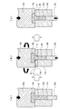
以下において、図面に基づいて本発明の実施形態を詳説する。図1は、本実施形態の製造工程説明図である。本実施形態はボルトの製造工程であって、特に螺子切り工程前における鍛造によるボルトの基体の形成工程である。 Hereinafter, embodiments of the present invention will be described in detail with reference to the drawings. FIG. 1 is an explanatory diagram of the manufacturing process of this embodiment. The present embodiment is a bolt manufacturing process, particularly a bolt base forming process by forging before the thread cutting process.
特に、本実施形態では、ボルト基体は、図1(a)の仮成形工程と、図1(b)の微細化領域形成工程と、図1(c)の本成形工程の三段階で形成を行っており、三段のパーツフォーマを用いて形成するようにしている。 In particular, in this embodiment, the bolt base is formed in three stages: a temporary forming step in FIG. 1A, a refined region forming step in FIG. 1B, and a main forming step in FIG. It is made using a three-stage part former.
仮成形工程では、仮成形用第1金型11aと、この仮成形用第1金型11aに対して進退自在とするとともに仮成形用第1金型11aに当接する仮成形用第2金型12aとで金属体Mを押圧して鍛造することにより、金属体Mを所定形状に仮成形するようにしている。
In the temporary forming step, the first
すなわち、仮成形用第1金型11aにはボルト基体の棒状部を形成するための収容孔13aを設けており、仮成形用第2金型12aにはボルト基体の頭部を形成するための頭部形成用凹部14aを設けている。さらに、仮成形用第1金型11aの収容孔13aには、この収容孔13aに沿って進退する仮成形用ピストン15aを挿入している。
That is, the
そして、仮成形用第1金型11aと仮成形用第2金型12aとで金属体Mを押圧して鍛造することによりボルト基体の仮成形を行い、仮成形用第2金型12aを仮成形用第1金型11aから離隔させて仮成形用ピストン15aで仮成形された金属体Mを押し出して、微細化領域形成工程に搬送するようにしている。工程間における金属体Mの搬送形態は適宜の形態としてよく、たとえば仮成形用第2金型12aに金属体Mを吸着させて、仮成形用第2金型12aによって金属体Mを次工程の微細化領域形成工程に搬送してもよい。
Then, the metal base M is pressed and forged by the first
本発明の要部である微細化領域形成工程では、微細化領域形成用第1金型11bと、この微細化領域形成用第1金型11bに対して進退自在とするとともに微細化領域形成用第1金型11bに当接する微細化領域形成用第2金型12bとによって金属体Mを押圧する際に、微細化領域形成用第2金型12bを微細化領域形成用第1金型11bに対して所定の角度だけ回転させることにより金属体Mに金属組織を微細化した微細化領域mを形成している。
In the refined region forming step, which is the main part of the present invention, the refined region forming
特に、微細化領域形成用第1金型11bにも、ボルト基体の棒状部となる金属体Mの棒状部分が挿入される収容孔13bを設けており、さらに、微細化領域形成用第1金型11bにおける微細化領域形成用第2金型12bとの当接面部分には、収容孔13bを回転中心として回転自在とした回転板11b'を設けている。
In particular, the
微細化領域形成用第2金型12bを微細化領域形成用第1金型11bに当接させて回転させる場合には、この回転板11b'が微細化領域形成用第1金型11bとともに回転することによって微細化領域形成用第2金型12bをスムーズに回転させることができ、短時間で確実に金属体Mを所定量だけ捻回させて微細化領域mを形成することができる。
When the
微細化領域形成用第2金型12bの微細化領域形成用第1金型11bに対する回転は、微細化領域形成用第2金型12bを微細化領域形成用第1金型11bに当接させながら行ってもよいし、微細化領域形成用第2金型12bを微細化領域形成用第1金型11bに所定の押圧力で当接させた後に行ってもよい。
The rotation of the
本実施形態では、微細化領域形成用第2金型12bの外側面に操作片(図示せず)を突設して、微細化領域形成用第2金型12bを微細化領域形成用第1金型11bに当接させるために近接させた際に、この操作片を所定角度の傾斜面からなる回動操作体(図示せず)に沿って摺動させることにより、微細化領域形成用第2金型12bを回転させながら微細化領域形成用第1金型11bに当接させるようにしている。そして、微細化領域形成用第2金型12bを微細化領域形成用第1金型11bから離隔させた場合には、微細化領域形成用第2金型12bを逆方向に回転させるように設けた付勢用バネ(図示せず)などの弾性体により、操作片を初期位置に復帰させるようにしている。なお、微細化領域形成用第2金型12bの回転操作機構は上記した機構に限定するものではなく、適宜の機構を用いることができる。
In the present embodiment, an operation piece (not shown) is provided on the outer surface of the
回転板11b'には、金属体Mが挿通される金属体挿通孔16を設けるとともに、この金属体挿通孔16の内周面を金属体Mと当接させない非当接面17としている。すなわち、金属体挿通孔16の内径は金属体Mの径寸法よりも大きい寸法として、非当接面17が金属体Mと当接しないようにしている。
The
このように、回転板11b'部分では回転板11b'と金属対Mとが当接しないようにしていることによって、微細化領域形成用第2金型12bが回転する場合に、金型11b,12bと当接していない金属対Mの非当接領域だけを捻回させることができる。
In this way, the
すなわち、金属体Mにおける微細化領域形成用第1金型11bの収容孔13bと当接した部分、及び微細化領域形成用第2金型12bに設けた頭部形成用凹部14bと当接した部分では、摩擦力が拘束力として作用することによって、微細化領域形成用第2金型12bの回転にともなった金属体Mの微細化領域形成用第1金型11b及び微細化領域形成用第2金型12bに対する回転方向の変位が生じないが、非当接領域では拘束力が何も作用しないことによって、微細化領域形成用第2金型12bの回転にともなって金属体Mは捻回されることとなる。
In other words, the metal body M is in contact with the
そして、この金属体Mの捻回にともなって金属体Mに剪断歪みを生じさせることにより金属組織を微細化することができ、微細化領域mを形成することができる。 Then, the metal structure can be refined by generating shear strain in the metal body M as the metal body M is twisted, and the refined region m can be formed.
本実施形態では、図1(b)に示すように、金属体挿通孔16を微細化領域形成用第2金型12bに向けて拡開状とすることにより非当接面17をテーパ形状としているが、非当接面17はこのようなテーパ形状に限定するものではなく適宜の形状としてよい。特に、金属体挿通孔16の内周面の一部は金属体Mと当接するようにしてもよく、非当接面17の大きさを調整することによって、微細化領域形成用第2金型12bの回転にともなって捻回される金属体Mの領域を調整することができる。
In the present embodiment, as shown in FIG. 1B, the
したがって、微細化領域mの大きさを調整することができるので、所望の大きさの微細化領域mを形成することができ、強度向上の調整を行うことができる。 Therefore, since the size of the miniaturized region m can be adjusted, the miniaturized region m having a desired size can be formed, and the strength improvement can be adjusted.
特に、微細化領域mは、本実施形態のようにボルト基体の棒状部と頭部の境界領域のような破損が生じやすい部分に形成して強度を向上させることにより、全体的な強度向上と同等の効果を得ることができる。 In particular, the refined region m is formed in a portion that is easily damaged, such as the boundary region between the rod-like portion of the bolt base and the head as in the present embodiment, thereby improving the overall strength. The same effect can be obtained.
微細化領域形成用第2金型12bの回転角度は、金属体の金属組織を微細化可能な剪断歪み生じさせることができる程度であればよく、所望する金属組織の微細化レベルと回転板11b'の厚み寸法あるいは非当接面17の面積とから決定されるものであり、通常であれば少なくとも10°以上回転すれば十分であり、好ましくは30°以上である。
The rotation angle of the
さらに、微細化領域形成用第1金型11bの収容孔13bには、この収容孔13bに沿って進退する微細化領域形成用ピストン15bを設けている。
Further, the
そして、微細化領域形成用ピストン15bは、微細化領域形成用第1金型11bと微細化領域形成用第2金型12bとを当接させるとともに微細化領域形成用第2金型12bを上記したように回転させる際に、金属体Mを微細化領域形成用第2金型12bの方向に押圧するようにしている。
The refined
このように、微細化領域の形成時に微細化領域形成用ピストン15bで金属体Mを押圧することにより、微細化領域形成用第2金型12bの回転にともなって金属体Mの捻回されている領域に破断が生じることを防止できる。
As described above, when the metal body M is pressed by the fine
本実施形態では、微細化領域形成用第1金型11bに対して微細化領域形成用第2金型12bを回転させるように構成しているが、微細化領域形成用第1金型11bを回転させるように構成してもよく、さらには、微細化領域形成用第1金型11bと微細化領域形成用第2金型12bの両方をそれぞれ回転させるように構成してもよい。
In the present embodiment, the
微細化領域形成用第1金型11bと微細化領域形成用第2金型12bとで金属体Mを押圧して鍛造することによりボルト基体に微細化領域mを形成した後、微細化領域形成用第2金型12bを微細化領域形成用第1金型11bから離隔させて微細化領域形成用ピストン15bで金属体Mを押し出して、本成形工程に搬送するようにしている。
After the metal body M is pressed and forged by the
本成形工程では、本成形用第1金型11cと、この本成形用第1金型11cに対して進退自在とするとともに本成形用第1金型11cに当接する本成形用第2金型12cとで金属体Mを押圧して鍛造することにより、金属体Mを所定形状に本成形するようにしている。
In the main molding step, the first
すなわち、本成形用第1金型11cにはボルト基体の棒状部を形成するための収容孔13cを設けており、本成形用第2金型12cには基体の頭部を形成するための頭部形成用凹部14cを設けている。さらに、本成形用第1金型11cの収容孔13cには、この収容孔13cに沿って進退する本成形用ピストン15cを挿入している。
That is, the
そして、本成形用第1金型11cと本成形用第2金型12cとで金属体Mを押圧するとともに、さらに本成形用ピストン15cで金属体Mを押圧して鍛造することによりボルト基体の本成形を行い、本成形用第2金型12cを本成形用第1金型11cから離隔させて本成形用ピストン15cで本成形された金属体Mを排出するようにしている。
Then, the metal body M is pressed by the
本実施形態では、仮成形工程と、微細化領域形成工程と、本成形工程の三段階で形成を行っているが、三段階による形成に限定するものではなく、一段階で形成するようにしてもよいし、必要に応じてさらに多くの工程を設けるようにしてもよい。 In the present embodiment, the formation is performed in three stages of a temporary molding process, a refined region forming process, and a main molding process. However, the present invention is not limited to the three-stage formation, and is formed in one stage. Alternatively, more steps may be provided as necessary.
また、本実施形態では、各第1金型11a,11b,11cに対して各第2金型12a,12b,12cをそれぞれ進退自在としているが、各第2金型12a,12b,12cに対して各第1金型11a,11b,11cをそれぞれ進退自在としてもよい。
In the present embodiment, each of the
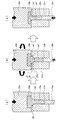
他の実施形態として、図2(a)に示す仮成形工程と、図2(b)に示す微細化領域形成工程と、図2(c)に示す本成形工程の三段階による鍛造を行うように構成してもよい。 As another embodiment, forging is performed in three stages: a temporary forming step shown in FIG. 2 (a), a refined region forming step shown in FIG. 2 (b), and a main forming step shown in FIG. 2 (c). You may comprise.
仮成形工程では、ボルト基体の棒状部を形成するための収容孔23aを設けた仮成形用第1金型21aと、ボルト基体の頭部を形成するための頭部形成用凹部24aを設けた仮成形用第2金型22aとで金属体M'を押圧して鍛造することによりボルト基体の仮成形を行い、仮成形用第2金型22aを仮成形用第1金型21aから離隔させて仮成形用ピストン25aで仮成形された金属体M'を押し出して、微細化領域形成工程に搬送するようにしている。
In the temporary forming step, a
特に、仮成形用第1金型21aには、収容孔23aの端部にテーパ形状の拡開部28を形成して、仮成形用第1金型21aと仮成形用第2金型22aとで金属体M'を押圧して鍛造した場合に、後工程の微細化領域形成工程で捻回されるボルト基体の棒状部と頭部との境界領域に、棒状部から頭部に向けて漸次拡径したテーパ形状を形成するようにしている。
In particular, the
このように、テーパ形状とした拡径部を設けた金属体M'を微細化領域形成工程に搬送し、微細化領域形成工程において拡径部に微細化領域m'を形成している。 As described above, the metal body M ′ provided with the tapered enlarged diameter portion is conveyed to the refined region forming step, and the refined region m ′ is formed in the enlarged diameter portion in the refined region forming step.
微細化領域形成工程では、回転板21b'を設けた微細化領域形成用第1金型21bの収容孔23bにボルト基体の棒状部を挿入し、頭部形成用凹部24bを設けた微細化領域形成用第2金型22bによって金属体M'を押圧するとともに、微細化領域形成用第1金型21bの収容孔23bに挿入した微細化領域形成用ピストン25bで金属体M'を押圧しながら、微細化領域形成用第2金型22bを微細化領域形成用第1金型21bに対して所定の角度だけ回転させることにより、金属体M'に金属組織を微細化した微細化領域m'を形成している。
In the refined region forming step, the rod-shaped portion of the bolt base is inserted into the
特に、回転板21b'は金属体M'に設けた拡径部の高さ寸法と略同等の厚み寸法を有するようにし、さらに、回転板21b'には、金属体M'が挿通される金属体挿通孔26を設けるとともに、この金属体挿通孔26の内周面を金属体M'と当接させない非当接面27としている。
In particular, the
微細化領域形成工程において金属体M'に設けた拡径部に微細化領域m'を形成した後に、本成形工程においてボルト基体の本成形を行っている。 After the refined region m ′ is formed in the enlarged diameter portion provided in the metal body M ′ in the refined region forming step, the bolt base is finally formed in the present forming step.
本成形工程では、収容孔23cを設けた本成形用第1金型21cと、頭部形成用凹部24cを設けた本成形用第2金型22cとで金属体M'を押圧するとともに、本成形用第1金型21cの収容孔23cに挿入した本成形用ピストン25cで金属体M'を押圧して鍛造することにより、金属体M'を所定形状に本成形するようにしている。
In the main molding step, the metal body M ′ is pressed with the first
このように、ボルト基体における微細化領域m'の形成部分をテーパ形状としていることによって、金属体M'を捻回した際に金属体M'に破断が生じることを防止できるとともに、金属体M'に形成される微細化領域m'を拡大化することができる。 In this way, by forming the portion where the miniaturized region m ′ in the bolt base is tapered, the metal body M ′ can be prevented from being broken when the metal body M ′ is twisted, and the metal body M ′ The “miniaturized region m” can be enlarged.
M,M' 金属体
m,m' 微細化領域
11a,21a 仮成形用第1金型
12a,22a 仮成形用第2金型
13a,23a 収容孔
14a,24a 頭部形成用凹部
15a,25a 仮成形用ピストン
11b,21b 微細化領域形成用第1金型
11b',21b' 回転板
12b,22b 微細化領域形成用第2金型
13b,23b 収容孔
14b,24b 頭部形成用凹部
15b,25b 微細化領域形成用ピストン
16,26 金属体挿通孔
17,27 非当接面
11c,21c 本成形用第1金型
13c,23c 収容孔
12c,22c 本成形用第2金型
14c,24c 頭部形成用凹部
15c,25c 本成形用ピストン
M, M 'metal body
m, m 'refined region
11a, 21a First mold for temporary molding
12a, 22a Second mold for temporary molding
13a, 23a receiving hole
14a, 24a Head forming recess
15a, 25a Temporary molding piston
11b, 21b First mold for forming miniaturized regions
11b ', 21b' rotating plate
12b, 22b Second mold for forming miniaturized regions
13b, 23b receiving hole
14b, 24b Head forming recess
15b, 25b Piston for forming miniaturized area
16,26 Metal body insertion hole
17,27 Non-contact surface
11c, 21c 1st mold for main molding
13c, 23c receiving hole
12c, 22c 2nd mold for main molding
14c, 24c Head forming recess
15c, 25c Main molding piston
Claims (13)
強度を向上させる領域の前記金属体の金属組織を微細化して微細化領域を形成したことを特徴とする鍛造成形品。 In forged molded products formed by forging a metal body,
A forged product characterized in that a refined region is formed by refining the metal structure of the metal body in the region where the strength is improved.
前記第1の金型と前記第2の金型とを当接させるときに、前記第1の金型と前記第2の金型との当接面に沿って、前記第1の金型と前記第2の金型との少なくともいずれか一方を他方に対して相対的に回転させる回転手段を設けたことを特徴とする鍛造装置。 In a forging device forging a metal body into a predetermined shape with a first mold and a second mold,
When the first mold and the second mold are brought into contact with each other, along the contact surface between the first mold and the second mold, the first mold and A forging apparatus comprising a rotating means for rotating at least one of the second mold relative to the other.
前記第1の金型と前記第2の金型とを当接させるときに、前記第1の金型と前記第2の金型との当接面に沿って、前記第2の金型を回転させる回転手段を設けたことを特徴とする鍛造装置。 Forging in which a metal body is inserted with a head projecting into an accommodation hole provided in a first mold, and the second mold is brought into contact with the first mold to forge the metal body into a predetermined shape. In the device
When the first mold and the second mold are brought into contact with each other, the second mold is moved along the contact surface between the first mold and the second mold. A forging device comprising a rotating means for rotating.
前記第1の金型と前記第2の金型とを当接させたときに、前記第1の金型と前記第2の金型との当接面に沿って、前記第1の金型と前記第2の金型との少なくともいずれか一方を他方に対して相対的に回転させることを特徴とする鍛造方法。 In a forging method in which a metal body is forged into a predetermined shape with a first mold and a second mold,
When the first mold and the second mold are brought into contact with each other, the first mold is formed along the contact surface between the first mold and the second mold. And a forging method, wherein at least one of the second mold and the second mold is rotated relative to the other.
前記第1の金型と前記第2の金型とを当接させたときに、前記第1の金型と前記第2の金型との当接面に沿って、前記第2の金型を回転させることを特徴とする鍛造方法。 Forging in which a metal body is inserted with a head projecting into an accommodation hole provided in a first mold, and the second mold is brought into contact with the first mold to forge the metal body into a predetermined shape. In the method
When the first mold and the second mold are brought into contact with each other, the second mold is formed along a contact surface between the first mold and the second mold. A forging method characterized by rotating the material.
Priority Applications (1)
| Application Number | Priority Date | Filing Date | Title |
|---|---|---|---|
| JP2004114722A JP4563716B2 (en) | 2004-04-08 | 2004-04-08 | Forging apparatus and forging method |
Applications Claiming Priority (1)
| Application Number | Priority Date | Filing Date | Title |
|---|---|---|---|
| JP2004114722A JP4563716B2 (en) | 2004-04-08 | 2004-04-08 | Forging apparatus and forging method |
Publications (2)
| Publication Number | Publication Date |
|---|---|
| JP2005296982A true JP2005296982A (en) | 2005-10-27 |
| JP4563716B2 JP4563716B2 (en) | 2010-10-13 |
Family
ID=35329162
Family Applications (1)
| Application Number | Title | Priority Date | Filing Date |
|---|---|---|---|
| JP2004114722A Expired - Fee Related JP4563716B2 (en) | 2004-04-08 | 2004-04-08 | Forging apparatus and forging method |
Country Status (1)
| Country | Link |
|---|---|
| JP (1) | JP4563716B2 (en) |
Cited By (2)
| Publication number | Priority date | Publication date | Assignee | Title |
|---|---|---|---|---|
| CN114713750A (en) * | 2022-03-31 | 2022-07-08 | 佛山市南海区锦华标准件厂 | A T-shaped nail head forming process |
| JP7669604B2 (en) | 2021-04-22 | 2025-04-30 | 旭サナック株式会社 | Die rotation device and forging machine |
Citations (3)
| Publication number | Priority date | Publication date | Assignee | Title |
|---|---|---|---|---|
| JPH067881A (en) * | 1992-06-25 | 1994-01-18 | Miyagawa Kinzoku Kogyo Kk | Manufacture of drill screw and forming die for the same |
| JP2003073787A (en) * | 2001-09-06 | 2003-03-12 | Japan Science & Technology Corp | Method for grain refinement of metal material and grain refiner |
| JP2005000996A (en) * | 2003-05-16 | 2005-01-06 | Susumu Mizunuma | Twist-upsetting lateral-extruding method for material and its apparatus |
-
2004
- 2004-04-08 JP JP2004114722A patent/JP4563716B2/en not_active Expired - Fee Related
Patent Citations (3)
| Publication number | Priority date | Publication date | Assignee | Title |
|---|---|---|---|---|
| JPH067881A (en) * | 1992-06-25 | 1994-01-18 | Miyagawa Kinzoku Kogyo Kk | Manufacture of drill screw and forming die for the same |
| JP2003073787A (en) * | 2001-09-06 | 2003-03-12 | Japan Science & Technology Corp | Method for grain refinement of metal material and grain refiner |
| JP2005000996A (en) * | 2003-05-16 | 2005-01-06 | Susumu Mizunuma | Twist-upsetting lateral-extruding method for material and its apparatus |
Cited By (2)
| Publication number | Priority date | Publication date | Assignee | Title |
|---|---|---|---|---|
| JP7669604B2 (en) | 2021-04-22 | 2025-04-30 | 旭サナック株式会社 | Die rotation device and forging machine |
| CN114713750A (en) * | 2022-03-31 | 2022-07-08 | 佛山市南海区锦华标准件厂 | A T-shaped nail head forming process |
Also Published As
| Publication number | Publication date |
|---|---|
| JP4563716B2 (en) | 2010-10-13 |
Similar Documents
| Publication | Publication Date | Title |
|---|---|---|
| JP4037613B2 (en) | Method for manufacturing tubular member | |
| US10876565B2 (en) | Self-piercing rivet | |
| JP5325934B2 (en) | Piercing nut manufacturing equipment | |
| JP2011025312A (en) | Method and apparatus for manufacturing inner and outer ring | |
| JP2006088197A (en) | Manufacturing method for axial product with expanded head, manufacturing method for engine valve, and forging die used for manufacturing axial product with expanded head | |
| WO2006088023A1 (en) | Metal member with through hole and method of manufacturing the same | |
| JP2009279642A (en) | Burring metallic mold, burring punch, and burring method | |
| KR101473948B1 (en) | Method for manufacturing flange structure | |
| JP2005296982A (en) | Forged product, forging device and forging method | |
| US1082910A (en) | Process of forging. | |
| US7673487B2 (en) | Method for forming hollow shaft with a flange and product with hollow shaft formed by the same | |
| JP2015036147A (en) | Punch for burring processing and burring processing method | |
| JP2010227988A (en) | Steel pipe expansion forming method and pipe expansion forming apparatus | |
| WO2021181834A1 (en) | Metalworking apparatus and metalworking method | |
| JPH10118722A (en) | Burring method and pressed products | |
| KR20120127974A (en) | Grain refining method for tubular metallic material | |
| JP5747448B2 (en) | Punching hole punching and punching hole machining method with improved fatigue characteristics and hydrogen cracking resistance | |
| JP6704319B2 (en) | Steel pipe expansion method | |
| CN105050750A (en) | Method for producing blind vias in metal bodies | |
| JP2000140976A (en) | Production of parts | |
| JP3430785B2 (en) | Flange forming method for pipe material | |
| JP3128208B2 (en) | Manufacturing method of ring-shaped parts | |
| JP4217691B2 (en) | Manufacturing method for cylindrical parts | |
| JP2009184064A (en) | Fracture method of metal member and fracture device of metal member | |
| JP2006043729A (en) | Prefabricated frame structure and method for manufacturing the same |
Legal Events
| Date | Code | Title | Description |
|---|---|---|---|
| A711 | Notification of change in applicant |
Free format text: JAPANESE INTERMEDIATE CODE: A711 Effective date: 20050728 |
|
| A521 | Request for written amendment filed |
Free format text: JAPANESE INTERMEDIATE CODE: A821 Effective date: 20050728 |
|
| A521 | Request for written amendment filed |
Free format text: JAPANESE INTERMEDIATE CODE: A523 Effective date: 20051129 |
|
| A711 | Notification of change in applicant |
Free format text: JAPANESE INTERMEDIATE CODE: A711 Effective date: 20060724 |
|
| A521 | Request for written amendment filed |
Free format text: JAPANESE INTERMEDIATE CODE: A821 Effective date: 20060724 |
|
| A621 | Written request for application examination |
Free format text: JAPANESE INTERMEDIATE CODE: A621 Effective date: 20070112 |
|
| A977 | Report on retrieval |
Free format text: JAPANESE INTERMEDIATE CODE: A971007 Effective date: 20080619 |
|
| A131 | Notification of reasons for refusal |
Free format text: JAPANESE INTERMEDIATE CODE: A131 Effective date: 20080902 |
|
| A521 | Request for written amendment filed |
Free format text: JAPANESE INTERMEDIATE CODE: A523 Effective date: 20081104 |
|
| A131 | Notification of reasons for refusal |
Free format text: JAPANESE INTERMEDIATE CODE: A131 Effective date: 20091006 |
|
| A521 | Request for written amendment filed |
Free format text: JAPANESE INTERMEDIATE CODE: A523 Effective date: 20091204 |
|
| A131 | Notification of reasons for refusal |
Free format text: JAPANESE INTERMEDIATE CODE: A131 Effective date: 20100105 |
|
| A521 | Request for written amendment filed |
Free format text: JAPANESE INTERMEDIATE CODE: A523 Effective date: 20100208 |
|
| A131 | Notification of reasons for refusal |
Free format text: JAPANESE INTERMEDIATE CODE: A131 Effective date: 20100518 |
|
| A521 | Request for written amendment filed |
Free format text: JAPANESE INTERMEDIATE CODE: A523 Effective date: 20100609 |
|
| TRDD | Decision of grant or rejection written | ||
| A01 | Written decision to grant a patent or to grant a registration (utility model) |
Free format text: JAPANESE INTERMEDIATE CODE: A01 Effective date: 20100629 |
|
| A01 | Written decision to grant a patent or to grant a registration (utility model) |
Free format text: JAPANESE INTERMEDIATE CODE: A01 |
|
| A61 | First payment of annual fees (during grant procedure) |
Free format text: JAPANESE INTERMEDIATE CODE: A61 Effective date: 20100729 |
|
| FPAY | Renewal fee payment (event date is renewal date of database) |
Free format text: PAYMENT UNTIL: 20130806 Year of fee payment: 3 |
|
| R150 | Certificate of patent or registration of utility model |
Ref document number: 4563716 Country of ref document: JP Free format text: JAPANESE INTERMEDIATE CODE: R150 Free format text: JAPANESE INTERMEDIATE CODE: R150 |
|
| R250 | Receipt of annual fees |
Free format text: JAPANESE INTERMEDIATE CODE: R250 |
|
| R250 | Receipt of annual fees |
Free format text: JAPANESE INTERMEDIATE CODE: R250 |
|
| R250 | Receipt of annual fees |
Free format text: JAPANESE INTERMEDIATE CODE: R250 |
|
| R250 | Receipt of annual fees |
Free format text: JAPANESE INTERMEDIATE CODE: R250 |
|
| R250 | Receipt of annual fees |
Free format text: JAPANESE INTERMEDIATE CODE: R250 |
|
| R250 | Receipt of annual fees |
Free format text: JAPANESE INTERMEDIATE CODE: R250 |
|
| R250 | Receipt of annual fees |
Free format text: JAPANESE INTERMEDIATE CODE: R250 |
|
| R250 | Receipt of annual fees |
Free format text: JAPANESE INTERMEDIATE CODE: R250 |
|
| R250 | Receipt of annual fees |
Free format text: JAPANESE INTERMEDIATE CODE: R250 |
|
| R250 | Receipt of annual fees |
Free format text: JAPANESE INTERMEDIATE CODE: R250 |
|
| LAPS | Cancellation because of no payment of annual fees |