JP2005296969A - Hydroforming method - Google Patents
Hydroforming method Download PDFInfo
- Publication number
- JP2005296969A JP2005296969A JP2004113115A JP2004113115A JP2005296969A JP 2005296969 A JP2005296969 A JP 2005296969A JP 2004113115 A JP2004113115 A JP 2004113115A JP 2004113115 A JP2004113115 A JP 2004113115A JP 2005296969 A JP2005296969 A JP 2005296969A
- Authority
- JP
- Japan
- Prior art keywords
- tube
- tensile strength
- expansion rate
- plate thickness
- mold
- Prior art date
- Legal status (The legal status is an assumption and is not a legal conclusion. Google has not performed a legal analysis and makes no representation as to the accuracy of the status listed.)
- Withdrawn
Links
Images
Landscapes
- Shaping Metal By Deep-Drawing, Or The Like (AREA)
Abstract
Description
本発明は、自動車用の排気系部品やサスペンション系部品等の製造に用いられるもので、金属管を分割した金型に入れ、当該金型を型締めした後、金属管内に内圧と管軸方向の押し力を負荷することにより所定形状に成形するハイドロフォーム加工方法に関する。 The present invention is used in the manufacture of exhaust system parts and suspension system parts for automobiles. The metal pipe is placed in a divided mold, and after the mold is clamped, the internal pressure and the axial direction of the pipe are in the metal pipe. The present invention relates to a hydroform processing method for forming a predetermined shape by applying a pressing force.
近年ハイドロフォーム技術は、部品数削減によるコスト削減や軽量化等の手段の一つとして自動車分野で注目を浴びており、欧米では数年前から既に実車に採用され、国内でも1999年から実車への適用も開始した。それ以降、ハイドロフォーム加工の適用部品は年々増加し、その市場規模は大幅に拡大してきた。ハイドロフォーム加工では成形する金属管に内圧を加えると同時に管端部からの軸押しを加えることにより材料を流入させ大きな変形を可能とすることができるが、この時、素管両端の拡管しない部分や、拡管部でも管端に近く、先に拡管が進行する部分では素管が金型に成型初期から密着してしまう為、摩擦抵抗により管端部から離れた部分に材料を効率良く流入させることが困難である。 In recent years, hydroform technology has been attracting attention in the automobile field as one of the means for reducing costs and reducing weight by reducing the number of parts. In Europe and the United States, it has already been adopted in actual vehicles for several years, and in Japan it has been changed from 1999 to actual vehicles. Started to apply. Since then, the number of applicable parts for hydroforming has increased year by year, and the market size has greatly expanded. In hydroforming, material can be allowed to flow in by applying internal pressure to the metal tube to be formed and at the same time pushing the shaft from the end of the tube, allowing significant deformation. Also, in the expanded portion, it is close to the end of the tube, and in the portion where the expansion of the tube proceeds first, the raw tube is in close contact with the mold from the beginning of molding, so the material efficiently flows into the portion away from the end of the tube due to frictional resistance. Is difficult.
また、場所により大きく拡管率が異なる部品を成形する場合も拡管率の小さい部分で成形初期に素管が金型に密着してしまい拡管率の大きい部分に材料を流入させることが困難となる。材料流入を向上させより成形限界を引き上げる為の方法としては、管軸方向に移動自在な可動金型を用いて金属管の管端部のみでなく可動型と接触する部分全体を拘束して押し込むことにより効率的に材料を流入させる手法が特許文献1、2および3に開示されているが、この手法では金型構造が複雑となる為、可動金型機構が組み込めるような部品形状のもののみに適用が限られる上、金型が高価なものになる。
Further, when molding a part having a large tube expansion ratio depending on the location, the raw tube is in close contact with the mold at the initial stage of molding at a portion where the tube expansion ratio is small, making it difficult to allow the material to flow into the portion where the tube expansion ratio is large. As a method for improving the material inflow and further raising the forming limit, not only the tube end of the metal tube but also the entire part in contact with the movable mold is restrained and pushed in using a movable mold movable in the tube axis direction.
また、特許文献4に鋼板の深絞り成形に関してフランジ部に良成形性の材料を接合して材料流入を容易にし深絞りの限界を向上させるプレス成形用テーラードブランク材の製造方法が開示されているがここでは、ハイドロフォーム成形の様に管端軸押しにより材料を流入させる場合については何ら言及していない。
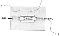
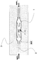
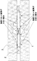
図1に示すように一般にハイドロフォーム成形においては、管端から軸押しポンチ2を用いて材料(素管1)を流入させ同時に水圧を負荷して成形を行うことで大きな変形が可能となる。ところが、従来のハイドロフォーム成形では、拡管しない素管の両端付近や拡管する部位でも管端に近く成型初期に金型と密着してしまう部分での金型と素管の摩擦抵抗により材料流入が妨げられ、部品中央部に充分に材料を流入させることができず、図2に示すように管端付近で座屈したり、部品中央部付近でバーストしてしまい易く、成形限界が低いものとなっている。
As shown in FIG. 1, in general, in hydroforming, large deformation is possible by injecting a material (element tube 1) from a tube end using a
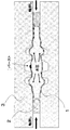
また、拡管率が大きく変化するような複雑な部品では、図3に示すように拡管率の小さい部分で素管と金型の密着が成形初期に起こり拡管率の大きい部位への材料流入を妨げる為、成形限界は低くなるという問題があった。 Further, in a complex part where the pipe expansion rate changes greatly, as shown in FIG. 3, the close contact between the raw tube and the mold occurs at the initial stage of molding at a portion where the pipe expansion rate is small, thereby preventing the material from flowing into the portion where the pipe expansion rate is large. Therefore, there is a problem that the molding limit is lowered.
本発明は、ハイドロフォーム成形において複雑な金型機構を用いることなく効率的に材料流入を引き起こし、成形限界を引き上げる加工方法を提供することを目的とする。 An object of the present invention is to provide a processing method that efficiently causes material inflow without using a complicated mold mechanism in hydroform molding and raises the molding limit.
本発明の要旨とするところは下記の通りである。
(1)軸方向において両端部の引張強度(TS)×板厚が他の一部又は全部の引張強度(TS)×板厚より15%以上大きい鋼管を金型に入れ、内圧と軸押しを負荷しながら加工することを特徴とするハイドロフォーム加工方法。
(2)拡管率が最大拡管率の60%以下となる部分の一部又は全部の引張強度(TS)×板厚が、最大拡管率となる部分の引張強度(TS)×板厚より15%以上大きい鋼管を金型に入れ、内圧と軸押しを負荷しながら加工することを特徴とするハイドロフォーム加工方法。
ただし、
拡管率=((製品の軸方向に垂直な断面の周長−素管の周長)/(素管の周長))×100(%)とする。
The gist of the present invention is as follows.
(1) In the axial direction, put a steel pipe whose tensile strength (TS) x plate thickness at both ends is 15% or more larger than the other part or all of the tensile strength (TS) x plate thickness in the mold, and press the internal pressure and axial push Hydroform processing method characterized by processing while loading.
(2) Tensile strength (TS) of part or all of the part where the expansion ratio is 60% or less of the maximum expansion ratio x plate thickness is 15% from the tensile strength (TS) of the part where the maximum expansion ratio is x plate thickness A hydroforming method characterized by putting a large steel pipe into a mold and processing it while applying internal pressure and axial push.
However,
Tube expansion rate = ((peripheral length of the cross section perpendicular to the axial direction of the product−perimeter of the raw tube) / (perimeter of the raw tube)) × 100 (%).
本発明によって、より成型限界の高いハイドロフォーム成形が可能となる。 According to the present invention, hydroform molding with a higher molding limit becomes possible.
以下、本発明を詳細に説明する。
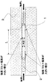
本発明では、ハイドロフォーム成形を行う際に図4、図5に示す様に、素管の管端部又は拡管率が最大拡管率の60%以下となる低拡管率部分の一部若しくは全部における引張強度(TS)×板厚を、それぞれ両端部を除く他の一部若しくは全部、又は最大拡管率の60%以上の拡管率となる大拡管率部分の一部若しくは全部の引張強度(TS)×板厚より15%以上大きくすることで、管端付近および低拡管率部分の拡管を抑えて、従来成形初期に生じていた素管と金型の密着を防ぎ、成形後半まで材料流入を効率的に引き起こすと共に管端部および低拡管率部分での座屈の発生を抑えることで従来より成形限界の高いハイドロフォーム成形が可能となる。
Hereinafter, the present invention will be described in detail.
In the present invention, when hydroforming is performed, as shown in FIGS. 4 and 5, the pipe end portion or the tube expansion rate of the raw tube is part or all of the low tube expansion rate portion where the maximum tube expansion rate is 60% or less. Tensile strength (TS) x plate thickness, part or all of the part other than both ends, or part or all of the large expansion rate part that makes the expansion rate 60% or more of the maximum expansion rate (TS) × By increasing the thickness by 15% or more than the plate thickness, it is possible to suppress the expansion of pipes near the pipe end and the low expansion ratio, prevent adhesion between the raw pipe and the mold, which has occurred in the early stages of molding, and efficiently inflow of material until the second half of molding. By suppressing the occurrence of buckling at the end of the tube and the portion with a low tube expansion ratio, hydroforming can be performed with a higher forming limit than before.
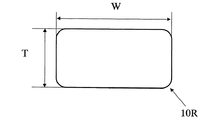
本発明の実施例として外径=63.5mm、板厚=2.3mm、で素管長=(軸押し量+100mm+拡管部長さL)の鋼管を用いて、図6に図4の拡管部の断面形状を示す様に、縦の長さT=63.5mmでコーナー部のR=10mmである長方形断面とし横の長さWを80mm、90mmの2通り、拡管部長さLを200mm、400mmの2通りに変化させた金型を用いて部品を成形した。素管は、STKM11Aの鋼管(引張強さ300MPa)の両端に80mmのSTKM13B(引張強さ400MPa)の鋼管を溶接して素管とした。また比較のため、素管の全長をSTKM11Aの鋼管とした場合に関しても成形をおこなった。板厚は本発明例、比較例とも、全て2.3mmとした。表1および表2に結果を示す(なお、表1、2に示す成形時の軸押し量は、左右同じ量とした。いずれの金型の場合も成形時の管端のシールは、O−リングを装着したノズルを用いて行った)。表中の○は座屈や破裂が無く成形できた場合を示し、×は、座屈や破裂が生じうまく成形できなかった場合を示す。また,表中の軸押し量は片側の値をあらわしている。表1および2の結果より、本発明は従来技術と比べて拡管部長さLが長く、拡管率の大きい成形品をつくることが可能であることがわかる。
As an embodiment of the present invention, a steel pipe having an outer diameter = 63.5 mm, a plate thickness = 2.3 mm, and a raw pipe length = (axial push amount + 100 mm + expanded portion length L) is used, and FIG. 6 shows a cross section of the expanded portion in FIG. As shown in the shape, a rectangular section with a vertical length T = 63.5 mm and a corner portion R = 10 mm, two horizontal lengths W of 80 mm and 90 mm, and a tube expansion portion length L of 200 mm and 400

1……素管
2……軸押しポンチ
3……金型
1 ... Raw
Claims (2)
ただし、
拡管率=((製品の軸方向に垂直な断面の周長−素管の周長)/(素管の周長))×100(%)とする。 Steel pipe whose tensile strength (TS) x plate thickness of the part where the pipe expansion rate is 60% or less of the maximum pipe expansion rate is 15% or more larger than the tensile strength (TS) x plate thickness of the part where the pipe expansion rate is maximum The hydroforming method is characterized in that it is put into a mold and processed while applying internal pressure and axial push.
However,
Tube expansion rate = ((peripheral length of the cross section perpendicular to the axial direction of the product−perimeter of the raw tube) / (perimeter of the raw tube)) × 100 (%).
Priority Applications (1)
| Application Number | Priority Date | Filing Date | Title |
|---|---|---|---|
| JP2004113115A JP2005296969A (en) | 2004-04-07 | 2004-04-07 | Hydroforming method |
Applications Claiming Priority (1)
| Application Number | Priority Date | Filing Date | Title |
|---|---|---|---|
| JP2004113115A JP2005296969A (en) | 2004-04-07 | 2004-04-07 | Hydroforming method |
Publications (1)
| Publication Number | Publication Date |
|---|---|
| JP2005296969A true JP2005296969A (en) | 2005-10-27 |
Family
ID=35329151
Family Applications (1)
| Application Number | Title | Priority Date | Filing Date |
|---|---|---|---|
| JP2004113115A Withdrawn JP2005296969A (en) | 2004-04-07 | 2004-04-07 | Hydroforming method |
Country Status (1)
| Country | Link |
|---|---|
| JP (1) | JP2005296969A (en) |
Cited By (4)
| Publication number | Priority date | Publication date | Assignee | Title |
|---|---|---|---|---|
| CN101570135A (en) * | 2008-04-29 | 2009-11-04 | 起亚自动车株式会社 | Tail trim assembly of exhaust pipe for vehicle and method of manufacturing the same |
| CN105855350A (en) * | 2016-03-29 | 2016-08-17 | 桂林电子科技大学 | Thin-wall metal pipe impact hydraulic forming method and device |
| CN107900181A (en) * | 2017-12-07 | 2018-04-13 | 平湖爱驰威汽车零部件有限公司 | A kind of automobile tail pipe former and application method |
| CN109622698A (en) * | 2018-12-06 | 2019-04-16 | 南京理工大学 | A kind of preparation facilities and method of the steel pipe that power distributes alternately |
-
2004
- 2004-04-07 JP JP2004113115A patent/JP2005296969A/en not_active Withdrawn
Cited By (7)
| Publication number | Priority date | Publication date | Assignee | Title |
|---|---|---|---|---|
| CN101570135A (en) * | 2008-04-29 | 2009-11-04 | 起亚自动车株式会社 | Tail trim assembly of exhaust pipe for vehicle and method of manufacturing the same |
| KR100962811B1 (en) * | 2008-04-29 | 2010-06-09 | 기아자동차주식회사 | Manufacturing method of tail trim of automotive exhaust pipe |
| US9101971B2 (en) | 2008-04-29 | 2015-08-11 | Kia Motors Corporation | Tail trim assembly of exhaust pipe for vehicle and method of manufacturing the same |
| CN105855350A (en) * | 2016-03-29 | 2016-08-17 | 桂林电子科技大学 | Thin-wall metal pipe impact hydraulic forming method and device |
| CN107900181A (en) * | 2017-12-07 | 2018-04-13 | 平湖爱驰威汽车零部件有限公司 | A kind of automobile tail pipe former and application method |
| CN109622698A (en) * | 2018-12-06 | 2019-04-16 | 南京理工大学 | A kind of preparation facilities and method of the steel pipe that power distributes alternately |
| CN109622698B (en) * | 2018-12-06 | 2020-04-07 | 南京理工大学 | Device and method for preparing steel pipes with alternately distributed strength |
Similar Documents
| Publication | Publication Date | Title |
|---|---|---|
| JP5009363B2 (en) | Hydroform processing method | |
| JP5868891B2 (en) | Manufacturing method of different diameter tubular parts | |
| JP6394254B2 (en) | Manufacturing method and manufacturing apparatus for expanded diameter pipe parts | |
| TWI711498B (en) | Formed material manufacturing method and formed material | |
| JP2006061944A (en) | Hydraulic bulge method, hydraulic bulge product and hydraulic bulge mold | |
| JP5009364B2 (en) | Method for manufacturing hydroformed products | |
| JP5307385B2 (en) | Manufacturing method of concentric expanded tube or eccentric expanded tube | |
| JP2005296969A (en) | Hydroforming method | |
| JP3972006B2 (en) | Hydroform processing method and hydroform processing mold | |
| JP6665643B2 (en) | Manufacturing method and manufacturing apparatus for expanded pipe parts | |
| JP2009045672A (en) | Hydroforming process for aluminum hollow extruded material | |
| JP2005095983A (en) | Bellows tube, manufacturing method thereof and mold | |
| JP6704319B2 (en) | Steel pipe expansion method | |
| JP6515274B2 (en) | Device and method for manufacturing end-thickened steel pipe | |
| JP2002282956A (en) | Hydroform processing method and apparatus | |
| JP2005288532A (en) | Hydroform processing method | |
| JP2019171407A (en) | Hydroforming method | |
| JP2003290845A (en) | Hydroforming method and mold for hydroforming | |
| JP3968047B2 (en) | Mold for hydroforming and hydroforming method | |
| JP2010253539A (en) | Forming tool for cylindrical end part | |
| JP4035073B2 (en) | Mold for hydroforming and hydroforming method | |
| JP4133465B2 (en) | Hydroform processing method | |
| JP6665644B2 (en) | Manufacturing method and manufacturing apparatus for expanded pipe parts | |
| JP4377529B2 (en) | Hydroform processing method of extruded aluminum | |
| JP2005111511A (en) | Hydroform processing method of tailored tube and hydrofoam molded product |
Legal Events
| Date | Code | Title | Description |
|---|---|---|---|
| A300 | Withdrawal of application because of no request for examination |
Free format text: JAPANESE INTERMEDIATE CODE: A300 Effective date: 20070703 |