JP2005296944A - Water quality improving system - Google Patents
Water quality improving system Download PDFInfo
- Publication number
- JP2005296944A JP2005296944A JP2005078487A JP2005078487A JP2005296944A JP 2005296944 A JP2005296944 A JP 2005296944A JP 2005078487 A JP2005078487 A JP 2005078487A JP 2005078487 A JP2005078487 A JP 2005078487A JP 2005296944 A JP2005296944 A JP 2005296944A
- Authority
- JP
- Japan
- Prior art keywords
- water
- filtration
- sensor
- flow rate
- pressure
- Prior art date
- Legal status (The legal status is an assumption and is not a legal conclusion. Google has not performed a legal analysis and makes no representation as to the accuracy of the status listed.)
- Pending
Links
- XLYOFNOQVPJJNP-UHFFFAOYSA-N water Substances O XLYOFNOQVPJJNP-UHFFFAOYSA-N 0.000 title claims abstract description 324
- 238000001914 filtration Methods 0.000 claims abstract description 118
- 230000007797 corrosion Effects 0.000 claims abstract description 95
- 238000005260 corrosion Methods 0.000 claims abstract description 95
- 238000001514 detection method Methods 0.000 claims abstract description 45
- 239000012466 permeate Substances 0.000 claims abstract description 15
- 238000012545 processing Methods 0.000 claims description 101
- 238000002407 reforming Methods 0.000 claims description 38
- 230000002159 abnormal effect Effects 0.000 claims description 27
- 230000002401 inhibitory effect Effects 0.000 claims description 24
- 230000001737 promoting effect Effects 0.000 claims description 17
- 230000005856 abnormality Effects 0.000 claims description 16
- 229910052751 metal Inorganic materials 0.000 claims description 14
- 239000002184 metal Substances 0.000 claims description 14
- 230000004907 flux Effects 0.000 claims description 8
- 230000001629 suppression Effects 0.000 claims description 7
- 230000005764 inhibitory process Effects 0.000 abstract description 4
- 238000012546 transfer Methods 0.000 description 35
- 239000012528 membrane Substances 0.000 description 31
- VYPSYNLAJGMNEJ-UHFFFAOYSA-N Silicium dioxide Chemical compound O=[Si]=O VYPSYNLAJGMNEJ-UHFFFAOYSA-N 0.000 description 24
- OKTJSMMVPCPJKN-UHFFFAOYSA-N Carbon Chemical compound [C] OKTJSMMVPCPJKN-UHFFFAOYSA-N 0.000 description 20
- 239000007789 gas Substances 0.000 description 20
- 238000000034 method Methods 0.000 description 15
- 238000001728 nano-filtration Methods 0.000 description 15
- 238000010586 diagram Methods 0.000 description 13
- 239000000377 silicon dioxide Substances 0.000 description 12
- 239000008234 soft water Substances 0.000 description 12
- 230000000694 effects Effects 0.000 description 11
- 230000008569 process Effects 0.000 description 10
- 239000000460 chlorine Substances 0.000 description 9
- ZAMOUSCENKQFHK-UHFFFAOYSA-N Chlorine atom Chemical compound [Cl] ZAMOUSCENKQFHK-UHFFFAOYSA-N 0.000 description 8
- QAOWNCQODCNURD-UHFFFAOYSA-L Sulfate Chemical compound [O-]S([O-])(=O)=O QAOWNCQODCNURD-UHFFFAOYSA-L 0.000 description 8
- 229910052801 chlorine Inorganic materials 0.000 description 8
- 230000007423 decrease Effects 0.000 description 7
- 230000006870 function Effects 0.000 description 7
- 238000011144 upstream manufacturing Methods 0.000 description 7
- QVGXLLKOCUKJST-UHFFFAOYSA-N atomic oxygen Chemical compound [O] QVGXLLKOCUKJST-UHFFFAOYSA-N 0.000 description 6
- 239000001301 oxygen Substances 0.000 description 6
- 229910052760 oxygen Inorganic materials 0.000 description 6
- 238000011045 prefiltration Methods 0.000 description 6
- 239000000126 substance Substances 0.000 description 6
- VEXZGXHMUGYJMC-UHFFFAOYSA-M Chloride anion Chemical compound [Cl-] VEXZGXHMUGYJMC-UHFFFAOYSA-M 0.000 description 5
- 239000007864 aqueous solution Substances 0.000 description 4
- 238000010438 heat treatment Methods 0.000 description 4
- NWUYHJFMYQTDRP-UHFFFAOYSA-N 1,2-bis(ethenyl)benzene;1-ethenyl-2-ethylbenzene;styrene Chemical compound C=CC1=CC=CC=C1.CCC1=CC=CC=C1C=C.C=CC1=CC=CC=C1C=C NWUYHJFMYQTDRP-UHFFFAOYSA-N 0.000 description 3
- 229910000975 Carbon steel Inorganic materials 0.000 description 3
- 230000001133 acceleration Effects 0.000 description 3
- 239000010962 carbon steel Substances 0.000 description 3
- 230000008859 change Effects 0.000 description 3
- 238000012937 correction Methods 0.000 description 3
- 238000007872 degassing Methods 0.000 description 3
- 238000006392 deoxygenation reaction Methods 0.000 description 3
- 239000003456 ion exchange resin Substances 0.000 description 3
- 229920003303 ion-exchange polymer Polymers 0.000 description 3
- 150000002739 metals Chemical class 0.000 description 3
- 230000007935 neutral effect Effects 0.000 description 3
- 230000003204 osmotic effect Effects 0.000 description 3
- 230000002093 peripheral effect Effects 0.000 description 3
- 238000011160 research Methods 0.000 description 3
- 230000004044 response Effects 0.000 description 3
- 230000000638 stimulation Effects 0.000 description 3
- RYGMFSIKBFXOCR-UHFFFAOYSA-N Copper Chemical compound [Cu] RYGMFSIKBFXOCR-UHFFFAOYSA-N 0.000 description 2
- 229910000881 Cu alloy Inorganic materials 0.000 description 2
- PXHVJJICTQNCMI-UHFFFAOYSA-N Nickel Chemical compound [Ni] PXHVJJICTQNCMI-UHFFFAOYSA-N 0.000 description 2
- 229910004298 SiO 2 Inorganic materials 0.000 description 2
- DWAQJAXMDSEUJJ-UHFFFAOYSA-M Sodium bisulfite Chemical compound [Na+].OS([O-])=O DWAQJAXMDSEUJJ-UHFFFAOYSA-M 0.000 description 2
- ZCDOYSPFYFSLEW-UHFFFAOYSA-N chromate(2-) Chemical compound [O-][Cr]([O-])(=O)=O ZCDOYSPFYFSLEW-UHFFFAOYSA-N 0.000 description 2
- 238000002485 combustion reaction Methods 0.000 description 2
- 238000001816 cooling Methods 0.000 description 2
- 229910052802 copper Inorganic materials 0.000 description 2
- 239000010949 copper Substances 0.000 description 2
- 238000007599 discharging Methods 0.000 description 2
- 239000000428 dust Substances 0.000 description 2
- 239000003673 groundwater Substances 0.000 description 2
- 239000012510 hollow fiber Substances 0.000 description 2
- 239000008235 industrial water Substances 0.000 description 2
- 238000005342 ion exchange Methods 0.000 description 2
- 239000007788 liquid Substances 0.000 description 2
- 238000000926 separation method Methods 0.000 description 2
- 235000012239 silicon dioxide Nutrition 0.000 description 2
- 235000010267 sodium hydrogen sulphite Nutrition 0.000 description 2
- 229910001415 sodium ion Inorganic materials 0.000 description 2
- 239000008399 tap water Substances 0.000 description 2
- 235000020679 tap water Nutrition 0.000 description 2
- OYPRJOBELJOOCE-UHFFFAOYSA-N Calcium Chemical compound [Ca] OYPRJOBELJOOCE-UHFFFAOYSA-N 0.000 description 1
- 229910001018 Cast iron Inorganic materials 0.000 description 1
- VYZAMTAEIAYCRO-UHFFFAOYSA-N Chromium Chemical compound [Cr] VYZAMTAEIAYCRO-UHFFFAOYSA-N 0.000 description 1
- FYYHWMGAXLPEAU-UHFFFAOYSA-N Magnesium Chemical compound [Mg] FYYHWMGAXLPEAU-UHFFFAOYSA-N 0.000 description 1
- 239000004952 Polyamide Substances 0.000 description 1
- 239000004721 Polyphenylene oxide Substances 0.000 description 1
- 239000005708 Sodium hypochlorite Substances 0.000 description 1
- RTAQQCXQSZGOHL-UHFFFAOYSA-N Titanium Chemical compound [Ti] RTAQQCXQSZGOHL-UHFFFAOYSA-N 0.000 description 1
- QCWXUUIWCKQGHC-UHFFFAOYSA-N Zirconium Chemical compound [Zr] QCWXUUIWCKQGHC-UHFFFAOYSA-N 0.000 description 1
- 229910052782 aluminium Inorganic materials 0.000 description 1
- XAGFODPZIPBFFR-UHFFFAOYSA-N aluminium Chemical compound [Al] XAGFODPZIPBFFR-UHFFFAOYSA-N 0.000 description 1
- 150000001450 anions Chemical group 0.000 description 1
- 230000033228 biological regulation Effects 0.000 description 1
- 230000000903 blocking effect Effects 0.000 description 1
- 238000007664 blowing Methods 0.000 description 1
- 239000011575 calcium Substances 0.000 description 1
- 229910052791 calcium Inorganic materials 0.000 description 1
- 229910052804 chromium Inorganic materials 0.000 description 1
- 239000011651 chromium Substances 0.000 description 1
- 238000004891 communication Methods 0.000 description 1
- 239000012530 fluid Substances 0.000 description 1
- 238000002347 injection Methods 0.000 description 1
- 239000007924 injection Substances 0.000 description 1
- 238000009434 installation Methods 0.000 description 1
- 239000011777 magnesium Substances 0.000 description 1
- 229910052749 magnesium Inorganic materials 0.000 description 1
- 238000012544 monitoring process Methods 0.000 description 1
- 229910052759 nickel Inorganic materials 0.000 description 1
- 239000007800 oxidant agent Substances 0.000 description 1
- 239000002245 particle Substances 0.000 description 1
- 238000002161 passivation Methods 0.000 description 1
- 229920002647 polyamide Polymers 0.000 description 1
- 229920000570 polyether Polymers 0.000 description 1
- 229920000642 polymer Polymers 0.000 description 1
- 238000001223 reverse osmosis Methods 0.000 description 1
- SUKJFIGYRHOWBL-UHFFFAOYSA-N sodium hypochlorite Chemical compound [Na+].Cl[O-] SUKJFIGYRHOWBL-UHFFFAOYSA-N 0.000 description 1
- 239000000243 solution Substances 0.000 description 1
- 238000001179 sorption measurement Methods 0.000 description 1
- 239000010935 stainless steel Substances 0.000 description 1
- 229910001220 stainless steel Inorganic materials 0.000 description 1
- 239000008400 supply water Substances 0.000 description 1
- 229920001059 synthetic polymer Polymers 0.000 description 1
- 239000010936 titanium Substances 0.000 description 1
- 229910052719 titanium Inorganic materials 0.000 description 1
- 238000000108 ultra-filtration Methods 0.000 description 1
- 238000004065 wastewater treatment Methods 0.000 description 1
- 229910052726 zirconium Inorganic materials 0.000 description 1
Images
Landscapes
- Separation Using Semi-Permeable Membranes (AREA)
- Degasification And Air Bubble Elimination (AREA)
- Physical Water Treatments (AREA)
Abstract
Description
この発明は、ボイラ等の熱機器への給水の水質を改質する水質改質システムに関する。 The present invention relates to a water quality reforming system for reforming the quality of water supplied to thermal equipment such as a boiler.
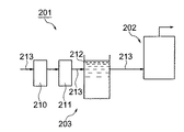
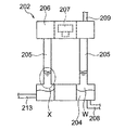
図10および図11において、引用符号201は貫流ボイラ202を含んで構成されるボイラシステムを示している。このボイラシステム201には、前記貫流ボイラ202の他に給水装置203が備えられている。前記貫流ボイラ202は、日本工業規格(JIS)に規定された特殊循環ボイラの範疇に属するボイラであって、前記貫流ボイラ202の下部に備えられ、前記給水装置203からの給水を貯留する給水貯留部204と、この給水貯留部204に立設される複数本の伝熱管205と、これらの伝熱管205の上端部に設けられるヘッダ206と、前記各伝熱管205内の給水を加熱して蒸気を生成するためのバーナ等の加熱装置207とを備えて構成されている。
10 and 11,
前記給水貯留部204および前記ヘッダ206は、平面視の形状が環状となるように形成されている。前記給水貯留部204には、その内部に貯留された給水(図11中のW)を排出することが可能な排出路208が形成されている。前記各伝熱管205は、後述する非不動態化金属を用いて形成されている。すなわち、前記各伝熱管205は非不動態化金属体である。このような構成の前記貫流ボイラ202により生成された蒸気は、前記ヘッダ206と接続される蒸気供給路209を介して負荷装置(図示省略)へ供給されるようになっている。
The water
前記給水装置203は、前記貫流ボイラ202へ給水を供給するためのものであって、軟水化装置210と、脱酸素装置211と、給水タンク212と、給水ライン213とを備えて構成されている。前記軟水化装置210は、給水中に含まれる硬度成分をイオン交換樹脂によりナトリウムイオンへ置換して軟水へ変換するように構成されている。また、前記脱酸素装置211は、給水中に含まれる溶存酸素を機械的に除去するように構成されている。前記脱酸素装置211の下流側の給水ライン213には、前記給水タンク212へ一定流量で処理水を流すために、定流量弁(図示省略)が設けられている。
The
前記給水ライン213を通じて前記貫流ボイラ202へ供給される給水は、前記給水貯留部204に貯留された後、前記加熱装置207により加熱されながら前記各伝熱管205内を上昇し、徐々に蒸気になる。そして、この蒸気は、前記ヘッダ206に集められ、前記蒸気供給路209を介して前記負荷装置へ供給される。
The water supplied to the once-through
前記非不動態化金属は、中性水溶液中において自然には不動態化しない金属を云い、通常は、ステンレス鋼,チタン,アルミニウム,クロム,ニッケルおよびジルコニウム等を除く金属である。具体的には、炭素鋼,鋳鉄,銅および銅合金等である。ここで、炭素鋼は、中性水溶液中においても、高濃度のクロム酸イオンの存在下では不動態化する場合があるが、この不動態化はクロム酸イオンの影響によるものであって、中性水溶液中での自然な不動態化とは言い難い。したがって、炭素鋼は、ここでの非不動態化金属の範疇に属する。また、銅および銅合金は、電気化学列(emf series)が貴な位置にあるため、通常は水分の影響による腐食が生じ難い金属と考えられているが、中性水溶液中において自然に不動態化するものではないので、ここでの非不動態化金属の範疇に属する。 The non-passivated metal refers to a metal that does not passivate naturally in a neutral aqueous solution, and is usually a metal other than stainless steel, titanium, aluminum, chromium, nickel, zirconium, and the like. Specifically, carbon steel, cast iron, copper, copper alloy, and the like. Here, carbon steel may passivate even in a neutral aqueous solution in the presence of a high concentration of chromate ions, but this passivation is due to the effects of chromate ions. It is hard to say that it is a natural passivating solution in aqueous solution. Therefore, carbon steel belongs to the category of non-passivated metals here. In addition, copper and copper alloys are considered to be metals that are unlikely to corrode due to the influence of moisture due to their noble position in the electrochemical column (emf series), but they are naturally passive in neutral aqueous solutions. It belongs to the category of non-passivated metals here.
前記構成において、複数の前記各伝熱管205は、図11中の一点鎖線で囲んだ円X内の部分,すなわち前記給水貯留部204と連続している下端部分が給水と継続的に接触するようになっている。このため、前記下端部分は、給水の影響を受けて腐食し易く、前記下端部分の内周面の減肉的な腐食や、肉厚方向に発生する微小な孔状の孔食が発生する。
In the above-described configuration, each of the plurality of
ところで、腐食を引き起こす主な要因としては、給水の溶存酸素濃度が高い場合,あるいは塩化物イオン濃度や硫酸イオン濃度等が高い場合などが一般的に知られているが、本願出願人においては、長年にわたって研究を続けた結果、つぎのことを確認している。すなわち、給水中に含まれる硫酸イオンが腐食促進成分として前記各伝熱管205などに作用することを確認している(たとえば、特許文献1)。また、本願出願人においては、給水中に含まれるシリカ(二酸化ケイ素(SiO2))が腐食を抑制する腐食抑制成分として前記各伝熱管205などに作用することも確認している(たとえば、特許文献2)。
腐食抑制方法として、薬剤を添加して対処する方法も数多く提案されているが、蒸気品質を高め、また排水処理の負荷を軽減する観点から、薬剤の使用量を削減しつつ腐食を抑制する方法の確立が望まれている。そこで、本願出願人においては、前記の研究結果から、給水中の腐食促進成分を捕捉し,かつ給水中の腐食抑制成分を透過する濾過部材,具体的にはナノ濾過膜(NF膜)を用いた従来にないシステムを提供しようとしている。 Many methods have been proposed to deal with corrosion by adding chemicals, but from the viewpoint of improving steam quality and reducing the wastewater treatment load, a method to suppress corrosion while reducing the amount of chemicals used. Establishment of is desired. Therefore, the applicant of the present application uses a filtration member, specifically a nanofiltration membrane (NF membrane) that captures the corrosion promoting component in the feed water and permeates the corrosion inhibiting component in the feed water based on the above research results. We are trying to provide an unprecedented system.
ところで、前記濾過部材にあっては、水温により水の粘性や膜特性が変化するため、濾過処理流量が大きく変化してしまう。濾過処理流量は、水温が低くなるほど低下するため、前記給水ラインに前記定流量弁を設ける場合には、低温時でも定格流量を確保することができるように、前記濾過部材へ給水を供給するための加圧ポンプの運転圧力を予め高く設定する必要がある。したがって、高温時には過剰な運転圧力になるため、年間を通じると、ほとんどがエネルギーロスになっている。 By the way, in the said filtration member, since the viscosity and film | membrane characteristic of water change with water temperature, the filtration process flow volume will change a lot. Since the filtration treatment flow rate decreases as the water temperature decreases, when the constant flow valve is provided in the water supply line, the supply water is supplied to the filtration member so that the rated flow rate can be secured even at low temperatures. The operating pressure of the pressure pump must be set high in advance. Therefore, excessive operating pressure occurs at high temperatures, so most of the energy is lost throughout the year.
この発明は、前記の事情に鑑みてなされたもので、その解決しようとする課題は、腐食抑制と省エネ運転に寄与する水質改質システムを実現することにある。 The present invention has been made in view of the above circumstances, and a problem to be solved is to realize a water quality reforming system that contributes to corrosion suppression and energy saving operation.
この発明は、前記課題を解決するためになされたもので、請求項1に記載の発明は、熱機器への給水の水質を改質する水質改質システムであって、非不動態化金属体の腐食を引き起こす腐食促進成分を捕捉するとともに、前記腐食の抑制に寄与する腐食抑制成分を透過する濾過処理部と、給水を前記濾過処理部へ供給するポンプと、前記濾過処理部からの透過水の流量を検知する流量センサと、前記ポンプの回転数を出力周波数に応じて可変させるインバータと、前記流量センサからの流量検知信号に基づいて、前記インバータへ指令信号を出力する制御部とを備えることを特徴とする。
The present invention has been made to solve the above-mentioned problems, and the invention according to
請求項1に記載の発明では、給水が前記ポンプにより前記濾過処理部へ供給される。前記濾過処理部へ供給された給水は、その中に含まれる腐食促進成分が捕捉されるとともに、腐食抑制成分が透過する。これにより、腐食促進成分が除去され,かつ腐食抑制成分が含まれる給水が生成され、この給水が前記熱機器へ供給される。ここに、前記熱機器としては、蒸気ボイラ,温水ボイラ,クーリングタワー,給湯器等が挙げられる。
In invention of
前記ポンプの運転は、前記インバータにより行われる。前記インバータへは、前記流量センサからの流量検知信号が、前記制御部を介して指令信号の形でフィードバックされる。これにより、水温変動などで処理流量が変化するような場合であっても、前記ポンプの回転数が前記インバータにより自動的に調節され、常に所定の処理流量が得られるような運転が行われる。 The pump is operated by the inverter. A flow rate detection signal from the flow rate sensor is fed back to the inverter in the form of a command signal via the control unit. As a result, even when the processing flow rate changes due to fluctuations in the water temperature or the like, the rotation speed of the pump is automatically adjusted by the inverter, and an operation that always obtains a predetermined processing flow rate is performed.
請求項2に記載の発明は、請求項1において、前記制御部は、前記流量センサの異常有無を監視し、前記流量センサに異常があったとき、前記濾過処理部を通過する給水の所定透過流速と、前記濾過処理部への給水,前記濾過処理部からの透過水,または前記濾過処理部からの濃縮水のいずれかの水温を検知する温度センサの検出値とに基づいてポンプ運転圧力を算出し、このポンプ運転圧力に基づいてポンプ運転周波数を算出し、このポンプ運転周波数に基づいて前記インバータへ指令信号を出力することを特徴とする。 According to a second aspect of the present invention, in the first aspect, the control unit monitors whether or not the flow rate sensor is abnormal. When the flow rate sensor is abnormal, the control unit transmits a predetermined amount of water that passes through the filtration processing unit. The pump operating pressure is determined based on the flow rate and the detected value of the temperature sensor that detects the water temperature of the water supplied to the filtration processing unit, the permeated water from the filtration processing unit, or the concentrated water from the filtration processing unit. And calculating a pump operating frequency based on the pump operating pressure, and outputting a command signal to the inverter based on the pump operating frequency.
請求項2に記載の発明では、前記流量センサが異常となったときのバックアップ対応が可能になる。すなわち、前記流量センサが異常となったときは、前記制御部により、前記所定透過流束と前記温度センサの検出値とに基づいて前記ポンプ運転圧力が算出され、このポンプ運転圧力に基づいて算出された前記ポンプ運転周波数に基づき、前記インバータへ指令信号が出力される。これにより、水温変動などで処理流量が変化するような場合であっても、前記インバータにより前記ポンプの回転数が調節され、常に所定の処理流量が得られるような運転が行われる。
In the invention according to
請求項3に記載の発明は、請求項1において、前記制御部は、前記流量センサの異常有無を監視し、前記流量センサに異常があったとき、前記濾過処理部への給水,前記濾過処理部からの透過水,または前記濾過処理部からの濃縮水のいずれかの水温を検知する温度センサからの温度検知信号に基づいて、前記インバータへ指令信号を出力することを特徴とする。 According to a third aspect of the present invention, in the first aspect, the control unit monitors whether or not the flow rate sensor is abnormal. When the flow rate sensor is abnormal, water supply to the filtration processing unit and the filtration processing are performed. A command signal is output to the inverter based on a temperature detection signal from a temperature sensor that detects the temperature of either the permeated water from the section or the concentrated water from the filtration processing section.
請求項3に記載の発明では、前記流量センサが異常となったときのバックアップ対応が可能になる。すなわち、前記流量センサが異常となったときは、前記温度センサからの温度検知信号が前記制御部で処理され、この制御部から前記インバータへ指令信号が出力される。これにより、水温変動などで処理流量が変化するような場合であっても、前記インバータにより前記ポンプの回転数が調節され、常に所定の処理流量が得られるような運転が行われる。 According to the third aspect of the present invention, it is possible to cope with backup when the flow sensor becomes abnormal. That is, when the flow sensor becomes abnormal, a temperature detection signal from the temperature sensor is processed by the control unit, and a command signal is output from the control unit to the inverter. As a result, even when the processing flow rate changes due to fluctuations in the water temperature or the like, the operation is performed such that the rotation speed of the pump is adjusted by the inverter and a predetermined processing flow rate is always obtained.
請求項4に記載の発明は、請求項1において、前記制御部は、前記流量センサの異常有無を監視し、前記流量センサに異常があったとき、前記濾過処理部への給水,前記濾過処理部からの透過水,または前記濾過処理部からの濃縮水のいずれかの水温を検知する温度センサからの温度検知信号と、給水の圧力または前記濾過処理部の濾過部材の有効圧力のいずれかを検知する圧力センサからの圧力検知信号とに基づいて、前記インバータへ指令信号を出力することを特徴とする。 According to a fourth aspect of the present invention, in the first aspect, the control unit monitors whether or not the flow rate sensor is abnormal. When the flow rate sensor is abnormal, water supply to the filtration processing unit and the filtration processing are performed. A temperature detection signal from a temperature sensor that detects the water temperature of either the permeated water from the section or the concentrated water from the filtration processing section, and the pressure of the water supply or the effective pressure of the filtration member of the filtration processing section A command signal is output to the inverter based on a pressure detection signal from a pressure sensor to be detected.
請求項4に記載の発明では、前記流量センサが異常となったときのバックアップ対応が可能になる。すなわち、前記流量センサが異常となったときは、前記温度センサからの温度検知信号および前記圧力センサからの圧力検知信号の二つの検知信号が前記制御部で処理され、この制御部から前記インバータへ指令信号が出力される。これにより、水温変動などで処理流量が変化するような場合であっても、前記インバータにより前記ポンプの回転数が調節され、常に所定の処理流量が得られるような運転が行われる。 According to the fourth aspect of the present invention, it becomes possible to cope with backup when the flow sensor becomes abnormal. That is, when the flow sensor becomes abnormal, two detection signals of a temperature detection signal from the temperature sensor and a pressure detection signal from the pressure sensor are processed by the control unit, and from this control unit to the inverter A command signal is output. As a result, even when the processing flow rate changes due to fluctuations in the water temperature or the like, the operation is performed such that the rotation speed of the pump is adjusted by the inverter and a predetermined processing flow rate is always obtained.
請求項5に記載の発明は、請求項2,3または4において、前記流量センサの異常を通報する通報手段を備えることを特徴とする。 A fifth aspect of the present invention is characterized in that in the second, third or fourth aspect of the present invention, a reporting means for reporting an abnormality of the flow sensor is provided.
請求項5に記載の発明では、前記通報手段を介して前記流量センサの異常が通報される。通報の後、前記流量センサが復旧するまでの間は、前記バックアップ対応が継続される。
In invention of
請求項6に記載の発明は、熱機器への給水の水質を改質する水質改質システムであって、非不動態化金属体の腐食を引き起こす腐食促進成分を捕捉するとともに、前記腐食の抑制に寄与する腐食抑制成分を透過する濾過処理部と、給水を前記濾過処理部へ供給するポンプと、前記濾過処理部への給水,前記濾過処理部からの透過水,または前記濾過処理部からの濃縮水のいずれかの水温を検知する温度センサと、前記ポンプの回転数を出力周波数に応じて可変させるインバータと、前記温度センサからの温度検知信号に基づいて、前記インバータへ指令信号を出力する制御部とを備えることを特徴とする。 The invention according to claim 6 is a water quality reforming system for reforming the quality of the water supplied to the thermal equipment, which captures the corrosion promoting component that causes the corrosion of the non-passivated metal body and suppresses the corrosion. A filtration processing unit that permeates a corrosion inhibiting component that contributes to the water, a pump that supplies feed water to the filtration processing unit, water supply to the filtration processing unit, permeated water from the filtration processing unit, or from the filtration processing unit Based on a temperature sensor that detects the temperature of any of the concentrated water, an inverter that varies the rotation speed of the pump according to an output frequency, and a temperature detection signal from the temperature sensor, a command signal is output to the inverter. And a control unit.
請求項6に記載の発明では、請求項1に記載の発明と同様、給水が前記ポンプにより前記濾過処理部へ供給される。前記濾過処理部へ供給された給水は、その中に含まれる腐食促進成分が捕捉されるとともに、腐食抑制成分が透過する。これにより、腐食促進成分が除去され,かつ腐食抑制成分が含まれる給水が生成され、この給水が前記熱機器へ供給される。
In the invention described in claim 6, similarly to the invention described in
ここで、前記ポンプの運転は、前記インバータにより行われる。前記インバータへは、前記温度センサからの温度検知信号が前記制御部で処理されて、この制御部から出力された指令信号が入力される。これにより、水温変動などで処理流量が変化するような場合であっても、前記インバータにより前記ポンプの回転数が自動的に調節され、常に所定の処理流量が得られるような運転が行われる。 Here, the operation of the pump is performed by the inverter. A temperature detection signal from the temperature sensor is processed by the control unit and a command signal output from the control unit is input to the inverter. As a result, even when the processing flow rate changes due to fluctuations in the water temperature or the like, the inverter automatically adjusts the rotational speed of the pump, and an operation is always performed to obtain a predetermined processing flow rate.
請求項7に記載の発明は、請求項6において、前記制御部は、前記濾過処理部を通過する給水の所定透過流束と前記温度センサの検出値とに基づいてポンプ運転圧力を算出し、このポンプ運転圧力に基づいてポンプ運転周波数を算出し、このポンプ運転周波数に基づいて前記インバータへ指令信号を出力することを特徴とする。 According to a seventh aspect of the present invention, in the sixth aspect, the control unit calculates a pump operating pressure based on a predetermined permeation flux of water passing through the filtration processing unit and a detection value of the temperature sensor, A pump operating frequency is calculated based on the pump operating pressure, and a command signal is output to the inverter based on the pump operating frequency.
請求項7に記載の発明では、前記制御部による温度検知信号の処理として、前記所定透過流束と前記温度センサの検出値とに基づいて前記ポンプ運転圧力が算出され、このポンプ運転圧力に基づいて前記ポンプ運転周波数が算出される。そして、このポンプ運転周波数に基づいて前記制御部から出力された指令信号が前記インバータへ入力される。これにより、水温変動などで処理流量が変化するような場合であっても、前記インバータにより前記ポンプの回転数が調節され、常に所定の処理流量が得られるような運転が行われる。 In the invention according to claim 7, as the processing of the temperature detection signal by the control unit, the pump operating pressure is calculated based on the predetermined permeation flux and the detected value of the temperature sensor, and based on the pump operating pressure. The pump operating frequency is calculated. And the command signal output from the said control part based on this pump operation frequency is input into the said inverter. As a result, even when the processing flow rate changes due to fluctuations in the water temperature or the like, the operation is performed such that the rotation speed of the pump is adjusted by the inverter and a predetermined processing flow rate is always obtained.
請求項8に記載の発明は、請求項1において、前記制御部は、前記温度センサからの温度検知信号と、給水の圧力または前記濾過処理部の濾過部材の有効圧力のいずれかを検知する圧力センサからの圧力検知信号とに基づいて、前記インバータへ指令信号を出力することを特徴とする。
The invention according to claim 8 is the pressure according to
請求項8に記載の発明では、前記温度センサからの温度検知信号および前記圧力センサからの圧力検知信号の二つの検知信号が前記制御部で処理され、この制御部から前記インバータへ指令信号が出力される。これにより、水温変動などで処理流量が変化するような場合であっても、前記インバータにより前記ポンプの回転数が調節され、常に所定の処理流量が得られるような運転が行われる。 In the invention according to claim 8, two detection signals of a temperature detection signal from the temperature sensor and a pressure detection signal from the pressure sensor are processed by the control unit, and a command signal is output from the control unit to the inverter. Is done. As a result, even when the processing flow rate changes due to fluctuations in the water temperature or the like, the operation is performed such that the rotation speed of the pump is adjusted by the inverter and a predetermined processing flow rate is always obtained.
請求項9に記載の発明は、請求項6,7または8において、前記制御部は、前記温度センサおよび/または前記圧力センサの異常有無を監視し、前記温度センサおよび/または前記圧力センサに異常があったとき、前記濾過処理部からの透過水の流量を検知する流量センサからの流量検知信号に基づいて、前記インバータへ指令信号を出力することを特徴とする。 A ninth aspect of the present invention provides the method according to the sixth, seventh, or eighth aspect, wherein the control unit monitors whether or not the temperature sensor and / or the pressure sensor is abnormal, and the temperature sensor and / or the pressure sensor is abnormal. When there is, a command signal is output to the inverter based on a flow rate detection signal from a flow rate sensor that detects the flow rate of the permeated water from the filtration processing unit.
請求項9に記載の発明では、前記温度センサまたは前記圧力センサが異常となったときのバックアップ対応が可能になる。すなわち、前記温度センサまたは前記圧力センサが異常となったときは、前記流量センサからの流量検知信号が前記制御部を介して指令信号の形で前記インバータへフィードバックされる。これにより、水温変動などで処理流量が変化するような場合であっても、前記インバータにより前記ポンプの回転数が調節され、常に所定の処理流量が得られるような運転が行われる。 According to the ninth aspect of the present invention, it is possible to cope with backup when the temperature sensor or the pressure sensor becomes abnormal. That is, when the temperature sensor or the pressure sensor becomes abnormal, a flow rate detection signal from the flow rate sensor is fed back to the inverter in the form of a command signal via the control unit. As a result, even when the processing flow rate changes due to fluctuations in the water temperature or the like, the operation is performed such that the rotation speed of the pump is adjusted by the inverter and a predetermined processing flow rate is always obtained.
請求項10に記載の発明は、請求項9において、前記温度センサおよび/または前記圧力センサの異常を通報する通報手段を備えることを特徴とする。
The invention described in
請求項10に記載の発明では、前記通報手段を介して前記温度センサまたは前記圧力センサの異常が通報される。通報の後、前記温度センサが復旧するまでの間は、前記バックアップ対応が継続される。
In invention of
請求項11に記載の発明は、請求項1,2,3,4,5,6,7,8,9または10において、給水に含まれる溶存気体を除去する溶存気体除去処理部を前記濾過処理部の下流側に接続することを特徴とする。
The invention according to
請求項11に記載の発明では、前記濾過処理部を通過した給水中に含まれる溶存気体が除去される。これにより、腐食促進成分と溶存気体とが除去され,かつ腐食抑制成分を含む給水が生成される。
In invention of
請求項1に記載された発明によれば、腐食抑制と省エネ運転に寄与する水質改質システムを実現することができるという効果を奏する。 According to the first aspect of the present invention, there is an effect that it is possible to realize a water quality reforming system that contributes to corrosion inhibition and energy saving operation.
請求項2,3,4に記載された発明によれば、それぞれ前記流量センサ異常時のバックアップ対応をすることができるという効果を奏する。 According to the invention described in the second, third, and fourth aspects, there is an effect that it is possible to cope with backup when the flow rate sensor is abnormal.
請求項5に記載された発明によれば、異常となった前記流量センサを早い段階で復旧させることができるという効果を奏する。
According to the invention described in
請求項6,7,8に記載された発明によれば、それぞれ腐食抑制と省エネ運転に寄与する水質改質システムを実現することができるという効果を奏する。 According to the invention described in claims 6, 7, and 8, it is possible to realize a water quality reforming system that contributes to corrosion inhibition and energy saving operation, respectively.
請求項9に記載された発明によれば、前記温度センサ異常時のバックアップ対応をすることができるという効果を奏する。 According to the ninth aspect of the present invention, there is an effect that it is possible to cope with backup when the temperature sensor is abnormal.
請求項10に記載された発明によれば、異常となった前記温度センサを早い段階で復旧させることができるという効果を奏する。 According to the tenth aspect of the invention, there is an effect that the temperature sensor that has become abnormal can be recovered at an early stage.
請求項11に記載された発明によれば、給水中に含まれる溶存気体を除去し、一層、腐食抑制に寄与することができるという効果を奏する。 According to the eleventh aspect of the present invention, there is an effect that the dissolved gas contained in the water supply can be removed and the corrosion can be further contributed to.
つぎに、この発明の実施の形態について、図面を参照して詳細に説明する。
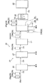
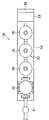
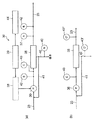
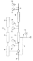
図1は、この発明の水質改質システムの一実施形態を示す構成図である。また、図2は、図1の水質改質装置の装置筐体の上蓋を取って見たときの図であり、図3(a)は、図1の水質改質装置の構成図であり、図3(b)は、圧力センサに関する補足説明図であり、図4は、図1の水質改質装置の他の構成図であり、図5は、ポンプの制御に係る説明図であり、図6は、省エネ効果の説明用のグラフであり、さらに図7は、制御部の一処理を示すフローチャートである。
Next, embodiments of the present invention will be described in detail with reference to the drawings.
FIG. 1 is a block diagram showing an embodiment of the water quality reforming system of the present invention. FIG. 2 is a diagram of the water quality reformer of FIG. 1 as viewed from the top cover of the device casing, and FIG. 3A is a configuration diagram of the water quality reformer of FIG. FIG. 3B is a supplementary explanatory diagram regarding the pressure sensor, FIG. 4 is another configuration diagram of the water quality reformer of FIG. 1, and FIG. 5 is an explanatory diagram relating to control of the pump. 6 is a graph for explaining the energy saving effect, and FIG. 7 is a flowchart showing one process of the control unit.
図1において、水質改質システム21は、熱機器22への給水の水質を改質するためのシステムであって、前記熱機器22へ給水を供給する給水ライン23と、この給水ライン23に接続される水処理装置24と、これらの水処理装置24で処理された給水を貯留する給水タンク25とを備えて構成されている。前記水処理装置24としては、とくに限定されないが、たとえば活性炭濾過装置26と、軟水装置27と、水質改質装置28と、複数の測定装置29(29a〜29h)とを備えている。前記水質改質装置28は、後述する装置筐体34内に組み込まれる装置主要部30により構成されている。そして、前記水質改質装置28の上流側には、プレフィルタ31が設けられている。
In FIG. 1, a water
前記水処理装置24の配置についてもう少し詳しく説明すると、原水側に設けられた被処理水タンク(図示省略)と接続された前記給水ライン23には、原水硬度を測定するための測定装置29aと、原水の残留塩素濃度を測定するための測定装置29bとが接続されている。そして、これらの各測定装置29a,29bの下流側には、前記活性炭濾過装置26が接続されている。前記活性炭濾過装置26の下流側には、前記軟水装置27が接続されている。この軟水装置27の下流側の前記給水ライン23には、給水の硬度を測定するための測定装置29cが接続されている。
Explaining the arrangement of the
前記測定装置29cの下流側には、前記プレフィルタ31と前記水質改質装置28の前記装置主要部30とが順に接続されている。前記プレフィルタ31と前記装置主要部30との間には、給水の濁度を測定するための測定装置29dと、給水の残留塩素濃度を測定するための測定装置29eとが接続されている。また、前記装置主要部30からの排水ライン40(詳細は後述)には、排水の硬度を測定するための測定装置29fが接続されている。前記装置主要部30の下流側の前記給水ライン23には、水質が改質された給水のシリカ濃度を測定するための測定装置29gと、水質が改質された給水の溶存酸素濃度を測定するための測定装置29hが接続されている。そして、これらの各測定装置29g,29hの下流側には、前記給水タンク25が接続されている。
The
ここで、前記被処理水タンクには、水道水,工業用水,地下水等の水源から供給される被処理水が貯留されている。被処理水は、前記水質改質システム21によりその水質が改質され、前記熱機器22へ供給されるようになっている。
Here, in the treated water tank, treated water supplied from a water source such as tap water, industrial water, and groundwater is stored. The water to be treated has its water quality modified by the water
前記熱機器22は、蒸気ボイラ,温水ボイラ,クーリングタワー,給湯器等であって、ここでは水管ボイラと称される多管式の貫流ボイラを例に挙げて説明する。この貫流ボイラの缶体構造は、図11で説明した前記貫流ボイラ202と同様に構成されている。すなわち、前記熱機器22である前記貫流ボイラ202は、所定の間隔で上下に配置される環状の前記給水貯留部204(以下「下部ヘッダ204」と云う。)および環状の前記ヘッダ206(以下、「上部ヘッダ206」と云う。)と、これらの各ヘッダ204,206の間に配置される複数の前記各伝熱管205と、前記各伝熱管205により区画形成される燃焼室(符号省略)と、この燃焼室の上方に配置され、前記各伝熱管205内の給水,いわゆる缶水を加熱して蒸気を生成させる加熱装置207(たとえば、バーナ)とを備えて構成されている。
The
前記下部ヘッダ204には、前記給水タンク25からの前記給水ライン23(すなわち、図11の前記給水ライン213)が接続されている。また、前記下部ヘッダ204には、蒸気の生成にともなって濃縮する缶水を系外へ排出する(ブローする)ための前記排出路208が設けられている。前記上部ヘッダ206には、生成された蒸気を負荷装置(図示省略)へ供給するための前記蒸気供給路209が設けられている。この構成において、前記下部ヘッダ204,前記各伝熱管205および前記上部ヘッダ206は、非不動態化金属を用いて形成されている(非不動態化金属については背景技術の欄を参照)。
The
前記活性炭濾過装置26は、給水中に溶存する次亜塩素酸ソーダに由来する残留塩素などの酸化剤を吸着除去するために接続されている。たとえば、前記残留塩素は、前記活性炭濾過装置26の下流側に配置される前記軟水装置27内のイオン交換樹脂(図示省略)を酸化させてイオン交換能力を早期に低下させるおそれがあり、また下流側に配置された前記水質改質装置28の後述するナノ濾過膜(図示省略)を酸化させて濾過能力を早期に低下させるおそれがある。そこで、前記残留塩素を活性炭で吸着して除去することにより、前記イオン交換能力の早期低下を防止するとともに前記濾過能力の早期低下を防止し、給水の処理効率の向上,安定化等を図るようにしている。
The activated
前記活性炭濾過装置26のような給水中の残留塩素を除去する他の装置としては、とくに図示しないが、重亜硫酸ナトリウム(SBS)を添加する薬注装置もあり、この装置を前記活性炭濾過装置26の替わりに適用してもよい。
As another device for removing residual chlorine in the feed water such as the activated
前記軟水装置27は、前記残留塩素が除去された給水中に含まれるカルシウムやマグネシウムの硬度成分をイオン交換樹脂(図示省略)により除去する装置として構成されている。すなわち、前記軟水装置27は、給水中に含まれる硬度成分をナトリウムイオンへ置換し、給水を軟水へ変換するために接続されている。
The
前記水質改質装置28は、図2に示されるごとく、前面にコントロールパネル32を有するとともに、このコントロールパネル32の裏側に制御ボックス33を有する装置筐体34の内部に、前記装置主要部30が収納される装置として構成されている(とくに限定するものではない。)。前記プレフィルタ31は、給水中のゴミ等を除去するためのものである。ここで、図2は、後述する筒状の濾過処理部35を3個連結した形態を概略的に図示している。前記濾過処理部35の設置方向は、図2に示す方向に限定されるものではなく、たとえばその軸方向が水平となる向きに設置されていてもよい。
As shown in FIG. 2, the
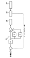
図3(a)において、前記装置主要部30は、濾過処理部35と、この濾過処理部35の上流側に接続されるポンプ36と、前記濾過処理部35の下流側に接続される流量センサ37と、前記ポンプ36に接続されるインバータ38と、このインバータ38を介して前記ポンプ36の制御および装置全体の制御を行う制御部39とを備えて構成されている。以下、これらの各部材とその周辺部材とについて説明する。
In FIG. 3A, the apparatus
前記濾過処理部35は、濾過部材,具体的には、ナノ濾過膜(NF膜,NF:Nanofiltration)を備えて構成されている。このナノ濾過膜は、ポリアミド系,ポリエーテル系等の合成高分子膜であり、2nm程度より小さい粒子や高分子(分子量が最大数百程度のもの)の透過を阻止することができる液体分離膜である。すなわち、前記ナノ濾過膜は、その濾過機能の点において、限外濾過膜(分子量が1,000〜300,000程度の物質を濾別可能な膜(UF膜))と、逆浸透膜(分子量が数十程度の物質を濾別可能な膜(RO膜))との中間に位置する液体分離膜として提供されている。前記ナノ濾過膜は、各社から市販されており、容易に入手することができる。前記ナノ濾過膜は、通常、濾過膜モジュールとして構成されている。この濾過膜モジュールの形態には、スパイラルモジュール,中空糸モジュール,平膜モジュール等がある。
The
さて、前記濾過処理部35の一側へは、前記ポンプ36から送り出された給水が流入するようになっている。前記濾過処理部35内へ流入した給水は、前記ナノ濾過膜により、腐食促進成分が捕捉されるとともに腐食抑制成分が透過されるようになっている。前記濾過処理部35の他側からは、透過水と濃縮水とがそれぞれ流出するようになっている。そして、透過水は、前記給水ライン23を流れて前記給水タンク25内に貯留されるようになっている。一方、濃縮水は、その一部が前記排水ライン40側へ流れるとともに、残部が循環水ライン41を流れて前記ポンプ36の上流側へ還流されるようになっている。
Now, water supplied from the
ここで、前記腐食促進成分および前記腐食抑制成分について説明する。まず、腐食促進成分とは、前記熱機器22,たとえば前記貫流ボイラ202の前記各伝熱管205の腐食が発生し易い部位,とくに内側に水分(ここでは缶水)が付着し,かつ外側から加熱される前記各伝熱管205の内面に作用してその腐食を促進するものを云い、通常、硫酸イオン(SO4 2−),塩化物イオン(Cl−)およびその他の成分を含んでいる。ちなみに、腐食促進成分として重要なものは、硫酸イオンおよび塩化物イオンの両者である。ところで、JIS B8223:1999は、前記貫流ボイラを含む特殊循環ボイラの腐食を抑制する観点から、当該ボイラの缶水の水質に関する各種の管理項目および推奨基準を規定している。この規定では、缶水の塩化物イオン濃度については管理値が設けられているものの、缶水の硫酸イオン濃度については言及していない。すなわち、このJISの規定は、硫酸イオンが腐食に関与するものとは認識していない。しかしながら、本願出願人においては、背景技術の欄でも説明したように、缶水に含まれる硫酸イオンが腐食促進成分として前記各伝熱管205などに作用していることを確認している。
Here, the said corrosion acceleration | stimulation component and the said corrosion suppression component are demonstrated. First, the corrosion promoting component is a portion where the corrosion of the
つぎに、腐食抑制成分とは、前記貫流ボイラ202の前記各伝熱管205の腐食が発生し易い部位,とくに前記各伝熱管205の内面に作用し、そこに生じる腐食を抑制可能なものを云い、通常、シリカ(すなわち、二酸化ケイ素(SiO2))を含んでいる。ところで、給水に含まれるシリカは、通常、前記各伝熱管205におけるスケール発生成分と認識されており、可能な限りその濃度を抑制することが好ましいと考えられている。しかしながら、本願出願人においては、背景技術の欄でも説明したように、缶水の水質と腐食との関係を長年にわたって研究した成果、缶水に含まれるシリカが腐食抑制成分として前記各伝熱管205などに作用していることを確認している。ここで、シリカは、給水として用いる水道水,工業用水,地下水等において、通常、含有されている成分である。
Next, the term “corrosion inhibiting component” refers to a component that acts on the portion of the once-through
さて、前記ポンプ36は、前記プレフィルタ31の下流側の前記給水ライン23を流れる,ゴミ等が除去された給水を前記濾過処理部35へ供給するためのものであって、その回転数は、前記ポンプ36に接続された前記インバータ38から出力される出力周波数に応じて可変するように構成されている(定流量制御がなされる。定流量制御については後述する。)。前記インバータ38は、前記制御部39と接続されている。また、前記インバータ38は、前記制御部39からの指令信号により作動するように構成されている。
Now, the
前記流量センサ37は、前記濾過処理部35を通過した透過水の流量を検知し、流量検知信号を前記制御部39へ出力するものであって、バルーンAで示される位置,すなわち前記濾過処理部35の下流側の前記給水ライン23に接続されている。前記流量センサ37からの流量検知信号は、前記インバータ38への指令信号の生成に用いられるようになっている。
The
前記濾過処理部35の上流側の前記給水ライン23,前記濾過処理部35の下流側の前記給水ライン23および前記排水ライン40に接続されるバルーンBは、温度センサ42の位置を示している。この温度センサ42は、これら三つの位置のいずれかに接続されており、給水,透過水または濃縮水の温度を検知して温度検知信号を前記制御部39へ出力するように構成されている。
A balloon B connected to the
前記濾過処理部35の上流側の前記給水ライン23に接続されるバルーンCは、圧力センサ(運転圧力センサ)43の位置を示している。この圧力センサ43は、前記濾過処理部35の上流側の給水の圧力を検知して圧力検知信号を前記制御部39へ出力するように構成されている。ここで、前記圧力センサ43は、図3(b)に示されるように、前記圧力センサ43と、前記濾過処理部35を通過した濃縮水の圧力を検知する圧力センサ43′(バルーンC′)とを設けるように構成してもよい。そして、これらの前記圧力センサ43,43′から出力される圧力検知信号に基づいて、前記制御部39で平均圧力[(給水の圧力+濃縮水の圧力)/2]を求め、この値を利用してもよい。また、前記濾過処理部35を通過した透過水の圧力を検知する圧力センサ43″(バルーンC″)を、前記圧力センサ43および前記圧力センサ43′の他にさらに設けるように構成してもよい。そして、前記平均圧力から透過水の圧力を差し引いて、前記濾過処理部35の前記濾過部材の有効圧力[{(給水の圧力+濃縮水の圧力)/2}−透過水の圧力]を求め、この値を利用してもよい。さらに、前記圧力センサ43および前記圧力センサ43″を設けるように構成し、給水の圧力から透過水の圧力を差し引いて前記濾過処理部35の前記濾過部材の有効圧力[給水の圧力−透過水の圧力]を求め、この値を利用してもよい。
A balloon C connected to the
前記温度センサ42および前記圧力センサ43は、この実施形態において、前記流量センサ37に異常があったときに、前記流量センサ37に代わってバックアップ対応をする重要な役割を有している(詳細は、後述する。)。
In this embodiment, the
前記制御部39は、いわゆるマイクロコンピュータであって、前記制御ボックス33の内部に備えられている。具体的には、CPU,ROM,RAMおよびインターフェース(それぞれ図示省略)を備えて構成されている。前記ROMには、プログラムや固定データ等が格納されている。前記CPUは、中央演算処理装置であり、前記ROMに予め格納された制御プログラムにしたがって作動するようになっている。前記RAMは、前記CPUの処理の過程で利用する各種のデータを格納するデータエリアと、処理の際に使用するワークエリアとを有している。その他、各種の設定値情報等が格納される電気的消去/書換え可能な読み出し専用のメモリも備えられている。
The
前記インターフェースには、前記流量センサ37,前記インバータ38,前記温度センサ42および前記圧力センサ43がそれぞれ接続されている。また、前記インターフェースには、前記装置筐体34の前面に配置される前記コントロールパネル32も接続されている。さらに、前記インターフェースには、異常を通報するための通報手段44や、警報を発する警報手段(図示省略)も接続されている。その他、前記インターフェースには、前記活性炭濾過装置26からの通信線なども接続されている。
The
つぎに、図4を参照しながら前記装置主要部30の他の構成例を説明する。以下の説明では、前記と同じ構成部材については同一の符号を付してその説明を省略する。
Next, another configuration example of the apparatus
図4において、前記装置主要部30は、前記濾過処理部35と、この濾過処理部35の上流側に接続される前記ポンプ36と、前記濾過処理部35の下流側に接続される溶存気体除去処理部45と、この溶存気体除去処理部45の下流側に接続される前記流量センサ37と、前記ポンプ36に接続される前記インバータ38と、このインバータ38を介しての前記ポンプ36の制御および装置全体の制御を行う前記制御部39と、バルーンBのいずれかの位置に接続される前記温度センサ42と、バルーンCの位置に接続される前記圧力センサ43とを備えて構成されている。
In FIG. 4, the apparatus
すなわち、図4の前記装置主要部30は、図3の前記装置主要部30に対して、前記溶存気体除去処理部45を増やした構成になっている。
That is, the apparatus
前記溶存気体除去処理部45は、給水に含まれる溶存気体を除去することができるように構成されている。もう少し詳しく説明(図示省略)すると、たとえば中空糸状の気体濾過膜を筒状のハウジング内に収容した複数の脱気モジュールと、水封式真空ポンプと、前記脱気モジュールおよび前記水封式真空ポンプを繋ぐ真空ラインと、前記濾過処理部35から回収した濃縮水を貯留する封水タンクと、前記水封式真空ポンプおよび前記封水タンクを繋ぐ封水循環ラインとを備えて構成されている。
The dissolved gas
前記脱気モジュールには、前記給水ライン23が接続されており、また前記真空ラインが接続されている。前記水封式真空ポンプは、前記各脱気モジュールから溶存気体を吸引するためのものであって、前記真空ラインと前記封水循環ラインとが接続されている。前記封水循環ラインは、前記封水タンクから前記水封式真空ポンプへ封水を供給するとともに、吸引した気体と封水との混合流体を前記封水タンクへ排出することができるように構成されている。
The deaeration module is connected to the
前記流量センサ37は、ここでは溶存気体を除去した後の流量を検知し、流量検知信号を前記制御部39へ出力するように構成されている。ここにおいて、前記流量センサ37は、前記濾過処理部35と前記溶存気体除去処理部45との間に接続してもよい。
Here, the
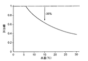
続いて、図5を参照しながら前記定流量制御(前記インバータ38によるPIDフィードバック制御)について説明する。この制御は、前記インバータ38のPID制御機能(P制御:比例制御,I制御:積分制御,D制御:微分制御)を使用し、実処理流量が目標値となるように、インバータ周波数を制御する機能である。前記ナノ濾過膜は、水温変動により水の粘性や膜特性が変化するため、処理流量が大きく変化する。具体的には、水温が低くなるほど処理流量は低下(約2.5%/1℃)するため、冬場など水温が10℃まで低下してしまうと、処理流量は、基準温度(たとえば、25℃)で設定した定格処理流量に比べて60%程度となる。処理流量と操作圧力は、ほぼ比例関係があり、水温による処理流量の低下分に応じて圧力を上げることで定格処理流量を得ることが可能になる。ところで、低温時に定格処理流量を得るように予め運転圧力を高く設定しておき、透過水の流れる側には定流量弁を設けることで一定流量を確保する方法が考えられる。しかしながら、この方法は冬場以外、過剰な運転となるためエネルギー的に非常にロスが大きくなる。そこで、前記水質改質システム21においては、設定した目標処理流量となるようにPID制御にて周波数を可変することで、常に理想的な運転を行い省エネを図っている。
Next, the constant flow control (PID feedback control by the inverter 38) will be described with reference to FIG. This control uses the PID control function (P control: proportional control, I control: integral control, D control: differential control) of the
PID制御は、図5に示されるように、前記流量センサ37からの流量検知信号を受けて前記制御部39が指令信号(たとえば、4〜20mAの電流値,もしくは1〜5Vの電圧値)を前記インバータ38へ出力する。前記インバータ38は、この指令信号をフィードバック値として目標値と比較を行い、その間に偏差があると、偏差をゼロにするように動作する(通常制御)。
As shown in FIG. 5, in the PID control, the
この発明によれば、図6のグラフに示されるような省エネ効果が得られる。すなわち、前記のように、予め運転圧力を高く設定し、透過水の流れる側には定流量弁を設ける場合の電力を1(一点鎖線)とすると、この発明では実線で示される結果が得られる。たとえば、15℃のところで判断すると、35%の省エネ効果が得られる。 According to the present invention, an energy saving effect as shown in the graph of FIG. 6 can be obtained. That is, as described above, if the operating pressure is set high in advance and the power when the constant flow valve is provided on the permeate flow side is 1 (one-dot chain line), the result shown by the solid line is obtained in the present invention. . For example, when judged at 15 ° C., an energy saving effect of 35% can be obtained.
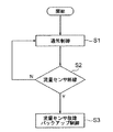
ところで、常に理想的な運転を行うために、前記制御部39は、つぎのような制御を行う必要がある。図7において、前記制御部39は、前記通常制御を行いつつ(ステップS1)、前記流量センサ37の異常有無を監視する(ステップS2)。この監視は、前記流量センサ37からの信号有無で判断する。前記流量センサ37からの信号があるときには、断線等の異常がないものと判断(ステップS2でN)し、通常制御を続ける。一方、前記流量センサ37からの信号が途絶えているときには、断線等の異常があるものと判断(ステップS2でY)し、ステップS3の処理へ移行する。このとき、異常があった旨を前記通報手段44を介して通報する(この時点で通報することにより復旧の作業が早まる。)。ステップS3の処理では、前記流量センサ37の故障等の異常時におけるバックアップ制御が行われる。
Incidentally, in order to always perform an ideal operation, the
ステップS3におけるバックアップ制御の一例について、図8および図9を参照して具体的に説明する。図8は、バックアップ制御における前記ポンプ36の制御に係る説明図であり、また図9は、バックアップ制御における制御部の一処理を示すフローチャートである。
An example of the backup control in step S3 will be specifically described with reference to FIGS. FIG. 8 is an explanatory diagram relating to the control of the
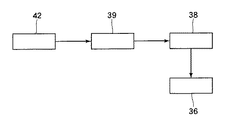
ステップS3のバックアップ制御において、前記温度センサ42からの温度検知信号が前記制御部39へ入力されると、この制御部39は、前記温度検知信号を処理し、前記インバータ38へ指令信号の出力を行う。前記インバータ38は、この指令信号に基づいて前記ポンプ36を制御する。
In the backup control in step S3, when a temperature detection signal from the
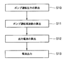
前記制御部39における前記温度検知信号の処理について、図9を参照して具体的に説明する。前記制御部39は、まず前記濾過処理部35を通過する給水の所定透過流束と前記温度センサ42の検出値とに基づいて前記ポンプ36の運転圧力(以下、「ポンプ運転圧力」と云う。)を算出する(ステップS10)。つぎに、このポンプ運転圧力に基づいて前記ポンプ36の運転周波数(以下、「ポンプ運転周波数」と云う。)を算出し(ステップS11)、さらにこのポンプ運転周波数に基づいて電流値を算出する(ステップS12)。そして、前記制御部39は、このポンプ運転周波数に対応した電流値を指令信号として前記インバータ38へ出力する(ステップS13)。これにより、目標処理流量となるように、前記ポンプ36が運転される。
The processing of the temperature detection signal in the
前記ステップS10における前記ポンプ運転圧力の算出について具体的に説明する。このポンプ運転圧力は、{定格流量/(平均透過流束×温度補正係数)}+装置差圧+出口背圧+浸透圧−原水圧力で算出される。ここで、前記定格流量は、単位時間あたりに前記濾過処理部35を通過させようとする透過水の流量,すなわち前記目標処理流量であり、前記平均透過流束は、前記所定透過流束に相当するものであって、基準温度(たとえば、25℃)において、単位時間および単位圧力あたりに前記濾過処理部35を通過する透過水の流量の平均値である。また、前記温度補正係数は、前記温度センサ42の検出値に基づいて算出される所定の値である。そして、前記装置差圧は、前記水質改質装置28の稼動開始時における前記濾過処理部35の入口側と出口側との間の水圧差であり、前記出口背圧は、前記濾過処理部35の出口側の背圧であり、さらに前記浸透圧は、前記ナノ濾過膜の一次側にかかる給水の浸透圧である。
The calculation of the pump operating pressure in step S10 will be specifically described. This pump operating pressure is calculated by {rated flow rate / (average permeation flux × temperature correction coefficient)} + device differential pressure + outlet back pressure + osmotic pressure−raw water pressure. Here, the rated flow rate is a flow rate of permeate to be passed through the
前記ステップS11における前記ポンプ運転周波数の算出について具体的に説明する。このポンプ運転周波数は、前記ステップS10において算出された前記ポンプ運転圧力をPとすると、A×P2+B×P+Cで算出される。ここで、A,B,Cは所定の係数である。 The calculation of the pump operation frequency in step S11 will be specifically described. The pump operating frequency is calculated as A × P 2 + B × P + C, where P is the pump operating pressure calculated in step S10. Here, A, B, and C are predetermined coefficients.
前記ステップS12における前記電流値の算出について具体的に説明する。この電流値は、前記ステップS11で算出された前記ポンプ運転周波数をFとすると、(F/X)×Y+Zで算出される。ここで、X,Y,Zは所定の係数である。 The calculation of the current value in step S12 will be specifically described. This current value is calculated as (F / X) × Y + Z, where F is the pump operating frequency calculated in step S11. Here, X, Y, and Z are predetermined coefficients.
以上、バックアップ制御の一例について説明したが、この発明においては、前記のようなバックアップ制御に限られるものではない。たとえば、前記制御部39は、前記温度センサ42からの温度検知信号に基づき(または、前記温度センサ42からの温度検知信号と前記圧力センサ43からの圧力検知信号とに基づき)、予め定めた,たとえば温度に対応する電流値(または、温度および圧力に対応する電流値)を指令信号として前記インバータ38へ出力し、このインバータ38によって前記ポンプ36を制御してもよい。
Although an example of the backup control has been described above, the present invention is not limited to the backup control as described above. For example, the
ここで、水温に対する処理流量の補正係数は、本願出願人における研究結果から、特定の前記ナノ濾過膜を使用した場合において、約2.5%/1℃であることが分かっているので、たとえば25℃を基準の前記ポンプ運転圧力(または、前記ポンプ運転周波数)に設定すると、水温が15℃まで低下すれば処理流量が約25%低下する。この場合、一定流量を確保するためには、前記ポンプ運転圧力をより高くすればよい。すなわち、単純に1/0.75=1.33倍の圧力をかければよく、このような前記ポンプ運転圧力となるような前記電流値が予め定められる。 Here, the correction coefficient of the treatment flow rate with respect to the water temperature is known to be about 2.5% / 1 ° C. when the specific nanofiltration membrane is used, based on the research results of the applicant of the present application. When 25 ° C. is set as the reference pump operating pressure (or the pump operating frequency), if the water temperature decreases to 15 ° C., the treatment flow rate decreases by about 25%. In this case, in order to ensure a constant flow rate, the pump operating pressure may be increased. That is, it is only necessary to simply apply a pressure of 1 / 0.75 = 1.33 times, and the current value to be such a pump operating pressure is determined in advance.
続いて、前記の構成に基づきながら、前記熱機器22の一例である前記貫流ボイラ202の運転時の作用について説明する。前記貫流ボイラ202を運転する場合には、前記被処理水タンクから供給される被処理水(水質改質前の給水)の水質を改質して給水を生成し、この給水を前記給水タンク25に貯留する必要がある。ここまでの過程について説明すると、前記給水ライン23を流れる給水は、前記被処理水タンクから所定の吐出圧を有する給水ポンプ(図示省略)により所定の圧力で供給される。この給水の圧力は、下流側に配置された前記水処理装置24における圧損等を考慮して設定される。そして、前記被処理水タンクから供給された給水は、まず前記活性炭濾過装置26を通過し、残留塩素が除去された状態の給水となる。つぎに、この給水は、前記軟水装置27を通過して軟水となる。続いて、この軟水化された給水は、前記水質改質装置28において濾過処理(および脱気処理)がなされ、前記貫流ボイラ202へ供給可能な給水となる。具体的には、軟水化された給水が前記水質改質装置28の前記濾過処理部35において、前記ナノ濾過膜を通過する際に、硫酸イオン,塩化物イオン等の腐食促進成分が前記ナノ濾過膜により捕捉される。すなわち、前記腐食促進成分が軟水から除去される。一方、軟水に含まれるシリカ,すなわち腐食抑制成分は、軟水とともに前記ナノ濾過膜を透過する。濾過処理後の前記腐食抑制成分を含む軟水化された給水は、前記貫流ボイラ202へ供給可能な給水として前記給水タンク25内に貯留される。ここにおいて、図4の構成の場合は、つぎのようになる。すなわち、濾過処理後の軟水化された給水は、前記水質改質装置28の前記溶存気体除去処理部45において溶存気体が脱気処理される。脱気処理後の前記腐食抑制成分を含む軟水化された給水は、前記貫流ボイラ202へ供給可能な給水として前記給水タンク25内に貯留される。
Next, the operation during operation of the once-through
前記給水タンク25内に貯留された給水は、前記給水タンク25および前記貫流ボイラ202の間に配置される給水ポンプ(図示省略)を介して前記貫流ボイラ202へ供給され、前記下部ヘッダ204内において缶水として貯留される。貯留された缶水は、前記加熱装置207により加熱されながら前記各伝熱管205内を上昇し、徐々に蒸気になる。そして、前記各伝熱管205内において生成された蒸気は、前記上部ヘッダ206内で集められ、前記蒸気供給路209から前記負荷装置へと供給される。
The feed water stored in the
前記貫流ボイラ202の運転中において、前記各伝熱管205は、その下端部分,すなわち前記下部ヘッダ204との連続する部分が缶水と継続的に接触することになる。このため、前記各伝熱管205は、下端部分において、通常、缶水の影響を受け腐食し易くなる。とくに、前記各伝熱管205は、下端部分において、内周面の減肉的な腐食に加えて局部的な腐食が生じ易く、これが原因で微小な穴開きを起こして破損する場合がある。
During the operation of the once-through
前記の局部的な腐食とは、前記各伝熱管205の缶水との接触面側から厚さ方向の反対側へ向かう孔状の腐食,すなわち前記各伝熱管205の厚さ(肉厚)方向に発生する孔状の腐食を云う。以下、このような局部的腐食の発生現象を「孔食」と云い、この孔食により生じた孔状の腐食を「食孔」と云う。ちなみに、孔食は、通常、缶水中の溶存酸素の影響により発生するものと理解されている。
The local corrosion is a hole-shaped corrosion from the contact surface side of each
しかしながら、この発明によれば、前記貫流ボイラ202の運転中において、前記各伝熱管205に対し、前記腐食抑制成分を含む軟水が缶水として供給されることになるので、缶水に含まれる前記腐食抑制成分が前記各伝熱管205の下端部分に作用し、当該部分の腐食を抑制するようになる。より具体的には、前記腐食抑制成分は、前記各伝熱管205の缶水との接触部分における減肉的な腐食を抑制するとともに、食孔の発生および成長も抑制し、腐食による前記伝熱管205の破損を抑制する。この際、缶水は、前記水質改質装置28により前記腐食促進成分が除去されるため、前記腐食抑制成分による前記のような腐食抑制作用は、前記腐食促進成分により阻害され難く、効果的に発揮されるようになる。
However, according to the present invention, during the operation of the once-through
さて、缶水に含まれる前記腐食抑制成分により、前記各伝熱管205の腐食が抑制されるのは、缶水に含まれる溶存酸素等(前記各伝熱管205の腐食促進成分)の影響により、前記各伝熱管205から溶出する成分に前記腐食抑制成分(とくに、シリカ)が作用し、前記各伝熱管205の内面に耐食性の皮膜(防食皮膜)が形成されるためと考えられる。とくに、溶存酸素は、前記各伝熱管205に局部的なアノードを発現させ、これにより孔食を進行させる場合があるが、缶水に含まれる前記腐食抑制成分(シリカ)は、アニオンまたは負電荷のミセルとして存在するため、前記アノードに吸着し易く、当該部分で選択的に防食皮膜を形成し易い。このため、缶水に含まれる前記腐食抑制成分(シリカ)は、前記各伝熱管205における孔食の進行をとくに効果的に抑制することができるものと考えられる。
Now, the corrosion inhibiting component contained in the can water suppresses the corrosion of each
以上、図1ないし図9を参照しながら説明してきたように、前記水質改質システム21は、薬剤を用いずに腐食を抑制することができる。また、前記水質改質システム21は、前記水質改質装置28において、前記インバータ38のPID制御機能を使用して、実処理流量が目標値となるようにインバータ周波数を制御することから、省エネ運転に寄与することができる。さらに、前記水質改質システム21は、熱機器用給水の処理効率を向上させることができるとともに、その処理の安定化を図ることができる。
As described above with reference to FIGS. 1 to 9, the water
この実施形態における前記水質改質システム21では、通常時には前記インバータ38のPID制御機能を使用した定流量制御を行い、バックアップ制御として、前記温度センサ42および/または前記圧力センサ43を使用した定流量制御を行うようにしているが、この発明はこのような構成に限定されるものではない。すなわち、通常時は、前記温度センサ42および/または前記圧力センサ43を使用した定流量制御を行い、バックアップ制御として前記インバータ38のPID制御機能を使用した定流量制御を行ってもよい。この場合、前記制御部39は、前記温度センサ42および/または前記圧力センサ43の異常有無を監視し、前記温度センサ42または前記圧力センサ43に異常があったときには、バックアップ制御として、前記流量センサ37からの流量検知信号に基づいて、前記インバータ38のPID制御機能を使用した定流量制御を行う。
In the water
その他、この発明は、その主旨を変えない範囲で種々変更実施可能なことは勿論である。 In addition, it goes without saying that the present invention can be variously modified without departing from the spirit of the present invention.
21 水質改質システム
22 熱機器
23 給水ライン
24 水処理装置
25 給水タンク
26 活性炭濾過装置
27 軟水装置
28 水質改質装置
29 測定装置
30 装置主要部
31 プレフィルタ
32 コントロールパネル
33 制御ボックス
34 装置筐体
35 濾過処理部
36 ポンプ
37 流量センサ
38 インバータ
39 制御部
40 排水ライン
41 循環水ライン
42 温度センサ
43 圧力センサ
44 通報手段
45 溶存気体除去処理部
DESCRIPTION OF
Claims (11)
非不動態化金属体の腐食を引き起こす腐食促進成分を捕捉するとともに、前記腐食の抑制に寄与する腐食抑制成分を透過する濾過処理部と、
給水を前記濾過処理部へ供給するポンプと、
前記濾過処理部からの透過水の流量を検知する流量センサと、
前記ポンプの回転数を出力周波数に応じて可変させるインバータと、
前記流量センサからの流量検知信号に基づいて、前記インバータへ指令信号を出力する制御部とを備える
ことを特徴とする水質改質システム。 A water quality reforming system for reforming the quality of water supplied to thermal equipment,
A filtration processing unit that captures a corrosion promoting component that causes corrosion of the non-passivated metal body and permeates the corrosion inhibiting component that contributes to the suppression of the corrosion,
A pump for supplying water to the filtration unit;
A flow rate sensor for detecting a flow rate of permeated water from the filtration unit;
An inverter that varies the number of rotations of the pump according to an output frequency;
A water quality reforming system comprising: a control unit that outputs a command signal to the inverter based on a flow rate detection signal from the flow rate sensor.
ことを特徴とする請求項1に記載の水質改質システム。 The control unit monitors whether or not the flow sensor is abnormal, and when there is an abnormality in the flow sensor, a predetermined permeation flow rate of the water passing through the filtration processing unit, water supply to the filtration processing unit, and the filtration processing The pump operating pressure is calculated based on the detected value of the temperature sensor for detecting the temperature of either the permeated water from the section or the concentrated water from the filtration processing section, and the pump operating frequency is calculated based on the pump operating pressure. The water quality reforming system according to claim 1, wherein the water quality reforming system calculates and outputs a command signal to the inverter based on the pump operating frequency.
ことを特徴とする請求項1に記載の水質改質システム。 The controller monitors whether or not the flow sensor is abnormal, and when there is an abnormality in the flow sensor, water supply to the filtration processing unit, permeated water from the filtration processing unit, or concentration from the filtration processing unit The water quality reforming system according to claim 1, wherein a command signal is output to the inverter based on a temperature detection signal from a temperature sensor that detects any water temperature of the water.
ことを特徴とする請求項1に記載の水質改質システム。 The controller monitors whether or not the flow sensor is abnormal, and when there is an abnormality in the flow sensor, water supply to the filtration processing unit, permeated water from the filtration processing unit, or concentration from the filtration processing unit Based on a temperature detection signal from a temperature sensor that detects the temperature of any of the water and a pressure detection signal from a pressure sensor that detects either the pressure of the water supply or the effective pressure of the filtration member of the filtration unit, The water quality reforming system according to claim 1, wherein a command signal is output to the inverter.
ことを特徴とする請求項2,3または4に記載の水質改質システム。 The water quality reforming system according to claim 2, 3 or 4, further comprising reporting means for reporting an abnormality of the flow sensor.
非不動態化金属体の腐食を引き起こす腐食促進成分を捕捉するとともに、前記腐食の抑制に寄与する腐食抑制成分を透過する濾過処理部と、
給水を前記濾過処理部へ供給するポンプと、
前記濾過処理部への給水,前記濾過処理部からの透過水,または前記濾過処理部からの濃縮水のいずれかの水温を検知する温度センサと、
前記ポンプの回転数を出力周波数に応じて可変させるインバータと、
前記温度センサからの温度検知信号に基づいて、前記インバータへ指令信号を出力する制御部とを備える
ことを特徴とする水質改質システム。 A water quality reforming system for reforming the quality of water supplied to thermal equipment,
A filtration processing unit that captures a corrosion promoting component that causes corrosion of a non-passivated metal body and permeates the corrosion inhibiting component that contributes to the suppression of the corrosion,
A pump for supplying water to the filtration unit;
A temperature sensor that detects the temperature of either the water supplied to the filtration unit, the permeated water from the filtration unit, or the concentrated water from the filtration unit;
An inverter that varies the number of rotations of the pump according to an output frequency;
A water quality reforming system comprising: a control unit that outputs a command signal to the inverter based on a temperature detection signal from the temperature sensor.
ことを特徴とする請求項6に記載の水質改質システム。 The control unit calculates a pump operating pressure based on a predetermined permeation flux of the feed water passing through the filtration processing unit and a detection value of the temperature sensor, calculates a pump operating frequency based on the pump operating pressure, The water quality reforming system according to claim 6, wherein a command signal is output to the inverter based on the pump operating frequency.
ことを特徴とする請求項6に記載の水質改質システム。 Based on the temperature detection signal from the temperature sensor and the pressure detection signal from the pressure sensor that detects either the pressure of the water supply or the effective pressure of the filtration member of the filtration processing unit, the control unit The water quality reforming system according to claim 6, wherein a command signal is output.
ことを特徴とする請求項6,7または8に記載の水質改質システム。 The control unit monitors whether the temperature sensor and / or the pressure sensor is abnormal, and detects the flow rate of permeated water from the filtration processing unit when the temperature sensor and / or the pressure sensor is abnormal. The water quality reforming system according to claim 6, 7 or 8, wherein a command signal is output to the inverter based on a flow rate detection signal from a flow rate sensor.
ことを特徴とする請求項9に記載の水質改質システム。 The water quality reforming system according to claim 9, further comprising reporting means for reporting an abnormality of the temperature sensor and / or the pressure sensor.
ことを特徴とする請求項1,2,3,4,5,6,7,8,9または10に記載の水質改質システム。 A dissolved gas removal processing section for removing dissolved gas contained in the feed water is connected to the downstream side of the filtration processing section, or 1, 2, 3, 4, 5, 6, 7, 8, 9 or The water quality reforming system according to 10.
Priority Applications (1)
| Application Number | Priority Date | Filing Date | Title |
|---|---|---|---|
| JP2005078487A JP2005296944A (en) | 2004-03-19 | 2005-03-18 | Water quality improving system |
Applications Claiming Priority (2)
| Application Number | Priority Date | Filing Date | Title |
|---|---|---|---|
| JP2004079636 | 2004-03-19 | ||
| JP2005078487A JP2005296944A (en) | 2004-03-19 | 2005-03-18 | Water quality improving system |
Publications (1)
| Publication Number | Publication Date |
|---|---|
| JP2005296944A true JP2005296944A (en) | 2005-10-27 |
Family
ID=35329131
Family Applications (1)
| Application Number | Title | Priority Date | Filing Date |
|---|---|---|---|
| JP2005078487A Pending JP2005296944A (en) | 2004-03-19 | 2005-03-18 | Water quality improving system |
Country Status (1)
| Country | Link |
|---|---|
| JP (1) | JP2005296944A (en) |
Cited By (3)
| Publication number | Priority date | Publication date | Assignee | Title |
|---|---|---|---|---|
| JP2008000658A (en) * | 2006-06-21 | 2008-01-10 | Miura Co Ltd | Membrane filtration system |
| WO2022142723A1 (en) * | 2020-12-31 | 2022-07-07 | 广东美的白色家电技术创新中心有限公司 | Water purification system and water purification device |
| CN115180743A (en) * | 2022-07-27 | 2022-10-14 | 东莞市珀蓝特机电设备有限公司 | Automatic cleaning device for cooling tower |
Citations (11)
| Publication number | Priority date | Publication date | Assignee | Title |
|---|---|---|---|---|
| JPS60165002U (en) * | 1984-04-06 | 1985-11-01 | 栗田工業株式会社 | Reverse osmosis membrane separation equipment |
| JPS63270592A (en) * | 1987-04-30 | 1988-11-08 | Ebara Corp | Fresh water generator by reverse-osmosis membrane module |
| JPH02174920A (en) * | 1988-12-27 | 1990-07-06 | Nitto Denko Corp | System for detecting abnormality of membrane separator |
| JPH0380991A (en) * | 1989-08-25 | 1991-04-05 | Takuma Co Ltd | Method and apparatus for treating supplied water to boiler |
| JPH0366697U (en) * | 1989-10-25 | 1991-06-28 | ||
| JPH09103770A (en) * | 1995-10-09 | 1997-04-22 | Akihisa Minato | Purified water producer device |
| JPH11333267A (en) * | 1998-05-27 | 1999-12-07 | Osaka Gas Co Ltd | Liquid filtration device and fuel cell generator using the device |
| JP2000218135A (en) * | 1999-01-28 | 2000-08-08 | Nitto Denko Corp | Membrane separation device and membrane separation method |
| JP2003136065A (en) * | 2001-11-05 | 2003-05-13 | Kurita Water Ind Ltd | Boiler feedwater treatment equipment |
| JP2003157869A (en) * | 2001-11-22 | 2003-05-30 | Kurita Water Ind Ltd | Water treating device for fuel cell |
| JP2004008934A (en) * | 2002-06-06 | 2004-01-15 | Asahi Kasei Corp | Operating method of membrane separation device |
-
2005
- 2005-03-18 JP JP2005078487A patent/JP2005296944A/en active Pending
Patent Citations (11)
| Publication number | Priority date | Publication date | Assignee | Title |
|---|---|---|---|---|
| JPS60165002U (en) * | 1984-04-06 | 1985-11-01 | 栗田工業株式会社 | Reverse osmosis membrane separation equipment |
| JPS63270592A (en) * | 1987-04-30 | 1988-11-08 | Ebara Corp | Fresh water generator by reverse-osmosis membrane module |
| JPH02174920A (en) * | 1988-12-27 | 1990-07-06 | Nitto Denko Corp | System for detecting abnormality of membrane separator |
| JPH0380991A (en) * | 1989-08-25 | 1991-04-05 | Takuma Co Ltd | Method and apparatus for treating supplied water to boiler |
| JPH0366697U (en) * | 1989-10-25 | 1991-06-28 | ||
| JPH09103770A (en) * | 1995-10-09 | 1997-04-22 | Akihisa Minato | Purified water producer device |
| JPH11333267A (en) * | 1998-05-27 | 1999-12-07 | Osaka Gas Co Ltd | Liquid filtration device and fuel cell generator using the device |
| JP2000218135A (en) * | 1999-01-28 | 2000-08-08 | Nitto Denko Corp | Membrane separation device and membrane separation method |
| JP2003136065A (en) * | 2001-11-05 | 2003-05-13 | Kurita Water Ind Ltd | Boiler feedwater treatment equipment |
| JP2003157869A (en) * | 2001-11-22 | 2003-05-30 | Kurita Water Ind Ltd | Water treating device for fuel cell |
| JP2004008934A (en) * | 2002-06-06 | 2004-01-15 | Asahi Kasei Corp | Operating method of membrane separation device |
Cited By (3)
| Publication number | Priority date | Publication date | Assignee | Title |
|---|---|---|---|---|
| JP2008000658A (en) * | 2006-06-21 | 2008-01-10 | Miura Co Ltd | Membrane filtration system |
| WO2022142723A1 (en) * | 2020-12-31 | 2022-07-07 | 广东美的白色家电技术创新中心有限公司 | Water purification system and water purification device |
| CN115180743A (en) * | 2022-07-27 | 2022-10-14 | 东莞市珀蓝特机电设备有限公司 | Automatic cleaning device for cooling tower |
Similar Documents
| Publication | Publication Date | Title |
|---|---|---|
| JP5158341B2 (en) | Preparation method for boiler feedwater | |
| JP2005296945A (en) | Water quality improving system | |
| JP2006305499A (en) | Operating method of membrane filtration system | |
| JP2010120015A (en) | Method of membrane filtration | |
| JP5953726B2 (en) | Ultrapure water production method and apparatus | |
| JP2009192193A (en) | Boiler system | |
| JP2010131579A (en) | System for improving water quality | |
| JP5240322B2 (en) | Water quality reforming system | |
| JP4687249B2 (en) | Water treatment system | |
| JP4996812B2 (en) | Water supply equipment | |
| JP2005288220A (en) | Water quality modifying system | |
| JP4165273B2 (en) | Boiler system | |
| JP2005296944A (en) | Water quality improving system | |
| JP2009192194A (en) | Boiler system | |
| JP2016032810A (en) | Water treatment system | |
| JP5013064B2 (en) | Supplying water for boiler feed water | |
| JP4359879B2 (en) | Water quality reformer | |
| JP5013063B2 (en) | Supplying water for boiler feed water | |
| JP2005288218A (en) | Water quality modifying system | |
| JP4544020B2 (en) | Operation method of membrane filtration system | |
| JP2005013851A (en) | Method and apparatus for treating supplied water for boiler | |
| JP2011050961A (en) | Water softener | |
| JP2005313034A (en) | Water supply system | |
| JP5013062B2 (en) | Supplying water for boiler feed water | |
| JP2010162500A (en) | Water quality modification system |
Legal Events
| Date | Code | Title | Description |
|---|---|---|---|
| A621 | Written request for application examination |
Free format text: JAPANESE INTERMEDIATE CODE: A621 Effective date: 20070918 |
|
| A977 | Report on retrieval |
Free format text: JAPANESE INTERMEDIATE CODE: A971007 Effective date: 20091014 |
|
| A131 | Notification of reasons for refusal |
Free format text: JAPANESE INTERMEDIATE CODE: A131 Effective date: 20091016 |
|
| A521 | Written amendment |
Free format text: JAPANESE INTERMEDIATE CODE: A523 Effective date: 20091209 |
|
| A131 | Notification of reasons for refusal |
Free format text: JAPANESE INTERMEDIATE CODE: A131 Effective date: 20101112 |
|
| A02 | Decision of refusal |
Free format text: JAPANESE INTERMEDIATE CODE: A02 Effective date: 20110304 |