JP2005296928A - Purifying material for waste water treatment, method of purifying waste water using the same and waste water treatment apparatus - Google Patents
Purifying material for waste water treatment, method of purifying waste water using the same and waste water treatment apparatus Download PDFInfo
- Publication number
- JP2005296928A JP2005296928A JP2004345751A JP2004345751A JP2005296928A JP 2005296928 A JP2005296928 A JP 2005296928A JP 2004345751 A JP2004345751 A JP 2004345751A JP 2004345751 A JP2004345751 A JP 2004345751A JP 2005296928 A JP2005296928 A JP 2005296928A
- Authority
- JP
- Japan
- Prior art keywords
- waste water
- purification material
- solution
- purification
- treatment
- Prior art date
- Legal status (The legal status is an assumption and is not a legal conclusion. Google has not performed a legal analysis and makes no representation as to the accuracy of the status listed.)
- Granted
Links
Images


Landscapes
- Solid-Sorbent Or Filter-Aiding Compositions (AREA)
- Treatment Of Water By Ion Exchange (AREA)
- Water Treatment By Sorption (AREA)
Abstract
Description
本発明は、硝酸イオン、亜硝酸イオン、フッ化物イオン等の陰イオンを吸着する排廃水処理用浄化材およびこれを用いた排廃水浄化方法並びに排廃水処理装置に関する。 The present invention relates to a wastewater treatment purification material that adsorbs anions such as nitrate ions, nitrite ions, and fluoride ions, a wastewater purification method using the same, and a wastewater treatment apparatus.
重金属、農薬、有機塩素化合物による水質や土壌の汚染は、環境を破壊するものとして問題になっている。これらの有害物質は活性炭やゼオライト等の吸着材で吸着除去することができるが、陰イオンの形態で存在する硝酸性窒素または亜硝酸性窒素、フッ素、ヒ素、シアン等は吸着材による処理が難しいのが現状である。 Water and soil contamination by heavy metals, pesticides and organochlorine compounds are problematic as they destroy the environment. These harmful substances can be adsorbed and removed by adsorbents such as activated carbon and zeolite, but nitrate nitrogen or nitrite nitrogen, fluorine, arsenic, cyanide, etc. present in the form of anions are difficult to treat with adsorbents. is the current situation.
例えば、硝酸性窒素や亜硝酸性窒素は、茶畑やゴルフ場芝地等の植物培養廃水に含まれる施肥による地下水汚染が深刻な問題となっており、その対策が必要であるが、有効な方法が見出されていない。また、化学工場、石油精製工場、鉄鋼・鋼材製造工場、製紙工場、半導体工場、産業廃棄物貯留場、繊維製造業における紡糸工場、食品工場からの廃水、さらには生活排水等に含まれる硝酸イオンや亜硝酸性イオンは、マイナス電荷を持ち、他の物と結合して難溶性の塩にならないため、マイナスに荷電している土壌から最も溶脱しやすく、現在、地下水等の水質汚染が大きな問題となっている上、最近では環境ホルモンである疑いが出てきている。 For example, nitrate nitrogen and nitrite nitrogen are serious problems due to groundwater contamination due to fertilization contained in plant culture wastewater such as tea plantations and golf course turf. Is not found. Nitrate ions contained in wastewater from chemical factories, petroleum refining factories, steel and steel manufacturing factories, paper mills, semiconductor factories, industrial waste storage, spinning factories in textile manufacturing, food factories, and domestic wastewater And nitrite ions are negatively charged and do not form a sparingly soluble salt when combined with other substances, so they are most easily leached from negatively charged soils, and water pollution such as groundwater is currently a major problem. In addition, recently it has been suspected of being an environmental hormone.
なお、排廃水から硝酸性窒素成分を除去する方法として脱窒菌を用いる方法も考えられているが、脱窒菌によって硝酸性窒素を除去するためには、嫌気条件を守りながら、水素供与体であるメタノール等の有機物の存在下で硝酸性窒素を還元しながら脱窒菌を増殖させて脱窒を行なう必要があり、運転操作が煩雑であり、維持管理に手間と費用がかかるという問題があった。 Although a method using denitrifying bacteria is also considered as a method for removing nitrate nitrogen components from wastewater, in order to remove nitrate nitrogen by denitrifying bacteria, it is a hydrogen donor while keeping anaerobic conditions. There is a problem that it is necessary to grow denitrifying bacteria while reducing nitrate nitrogen in the presence of organic substances such as methanol to perform denitrification, and the operation operation is complicated, and maintenance and management are troublesome and expensive.
また、近年は、医薬品、農薬、機能性薬品、高分子などにその特性からフッ素を含んだものが数多く製造されており、今後益々広く用いられる傾向にある。このため、これらの化合物を合成したり、使用するときに、工場廃水や各家庭、合併浄化槽、集落単位における生活排水にフッ素が含まれる。加えて、フッ素は、ガラス、メッキ工業、金属精錬、金属表面処理、窯業工業、半導体などの電子工業、化学工業などの産業排水に含まれている。ところが、フッ化物イオンは有害なイオン種であるから、環境保全のために排廃水に何らかの処理をしてフッ化物イオンを排出する必要がある。 In recent years, a large number of pharmaceuticals, agricultural chemicals, functional chemicals, polymers, and the like containing fluorine are produced due to their characteristics, and they tend to be used more and more in the future. For this reason, when these compounds are synthesized or used, fluorine is contained in factory wastewater, households, combined septic tanks, and household wastewater in village units. In addition, fluorine is contained in industrial wastewater from the glass, plating industry, metal refining, metal surface treatment, ceramic industry, electronics industry such as semiconductor, and chemical industry. However, since fluoride ions are harmful ion species, it is necessary to discharge the fluoride ions by performing some kind of treatment on waste water for environmental protection.
そこで、各種排廃水中のフッ素にカルシウム化合物を添加し、フッ化カルシウムとしてこれを除去する方法がとられているが、活性アルミナやフッ素用の陰イオン交換樹脂による吸着塔の設置が必要で大きなコストがかかっている。また、環境基準0.8mg/L以下にしようとすると、高価な専用の陰イオン交換樹脂が必要となる。その他、ヒ素やシアンなども工場排水や、地下水汚染の処理には高価な陰イオン交換樹脂が必要である。 Therefore, a method has been adopted in which a calcium compound is added to fluorine in various wastewaters and removed as calcium fluoride. However, it is necessary to install an adsorption tower with activated alumina or an anion exchange resin for fluorine. There is a cost. Further, if the environmental standard is 0.8 mg / L or less, an expensive dedicated anion exchange resin is required. In addition, arsenic and cyanide require expensive anion exchange resins for the treatment of industrial wastewater and groundwater contamination.
一方、排廃水からフッ素を除去するために、吸着材を利用する方法としては、樹脂母体に金属水和物を担持させたもの又はイオン交換樹脂に金属を吸着させたものや、陽イオン交換樹脂にトリウム、ジルコニウム、チタニウムなどの金属イオンを吸着させたフッ化物イオン吸着材などが考えられている。しかしながら、これらの吸着材は吸着速度が遅いという問題があった。 On the other hand, in order to remove fluorine from waste water, as a method of using an adsorbent, a resin matrix carrying a metal hydrate or a metal adsorbed on an ion exchange resin, a cation exchange resin Fluoride ion adsorbents in which metal ions such as thorium, zirconium, and titanium are adsorbed are considered. However, these adsorbents have a problem that the adsorption speed is slow.
上述のように、硝酸イオンをはじめとする上記陰イオンを吸着する安価な材料は、現在のところなく、このため、これらの陰イオンによる汚染は広まる傾向にあり、前記陰イオンに一度汚染されると、その修復には多大なコストが必要となる。
そこで安価で環境にやさしい陰イオン吸着素材が求められている。活性炭とともに代表的な多孔質炭素材料である木炭は、調湿材、河川浄化材、土壌改良材などとして広く用いられており、例えば、排ガス中の塩素系ガスや硫黄酸化物などの除去にも利用されている。これは、活性炭と同様に、多孔質炭素材料の内部の微細孔による吸着特性を利用しているに過ぎず、陰イオンの形態で存在する硝酸性窒素または亜硝酸性窒素あるいはフッ素、ヒ素、シアンなどはほとんど吸着しない。 Therefore, there is a need for an anion adsorption material that is inexpensive and environmentally friendly. Charcoal, which is a typical porous carbon material together with activated carbon, is widely used as a humidity control material, river purification material, soil improvement material, etc. For example, for removing chlorine-based gas and sulfur oxide in exhaust gas It's being used. This, like activated carbon, only uses the adsorption characteristics due to the fine pores inside the porous carbon material, and nitrate nitrogen or nitrite nitrogen or fluorine, arsenic, and cyanide that exist in the form of anions. Almost no adsorption.
本発明は、上述の事柄を考慮に入れてなされたものであって、その目的は、安価で環境に優しく陰イオン吸着性に優れた排廃水処理用浄化材およびこれを用いた排廃水浄化方法並びに排廃水処理装置を提供することである。 The present invention has been made in consideration of the above-mentioned matters, and an object of the present invention is to provide a wastewater treatment purification material that is inexpensive, environmentally friendly and excellent in anion adsorption, and a wastewater purification method using the same. In addition, the present invention is to provide a waste water treatment apparatus.
本発明者らは、酸溶液を炭化物に接触させて得られた材料について陰イオンの吸着性能を検討した結果、天然繊維、木質材料等の原料植物(植物からなる原料)に対する炭化処理温度、酸の濃度にも依るが、得られた材料が優れた陰イオンの吸着性能を有することを知見するに至った。 As a result of studying the anion adsorption performance of the material obtained by bringing the acid solution into contact with the carbide, the present inventors have found that the carbonization treatment temperature and acid for the raw material plant (raw material consisting of plants) such as natural fiber and woody material. It was found that the obtained material has excellent anion adsorption performance, although it depends on the concentration of the anion.
すなわち、例えば、原料植物としての木材を炭化して得られる木炭に、塩酸(HCl)、硫酸(H2 SO4 )等の酸溶液を接触(酸処理)させれば、陰イオンの吸着能が発現されるのを本発明者らは見出した。これは原料植物の微細孔壁面に存在する官能基に、吸着対象の陰イオンとイオン交換可能である陰イオンが結合したためである。なお、酸溶液を炭化物に接触させる方法としては、酸溶液の滴下、塗布、吹付、噴霧などが可能であるが、炭化物を酸溶液に浸漬させることが最も効果的である。 That is, for example, if an acid solution such as hydrochloric acid (HCl) or sulfuric acid (H 2 SO 4 ) is brought into contact (acid treatment) with charcoal obtained by carbonizing wood as a raw material plant, the ability to adsorb anions can be obtained. The inventors have found that it is expressed. This is because an anion that can be ion-exchanged with the anion to be adsorbed is bonded to the functional group present on the microporous wall surface of the raw material plant. In addition, as a method of bringing the acid solution into contact with the carbide, the acid solution can be dropped, applied, sprayed, sprayed, etc., but it is most effective to immerse the carbide in the acid solution.
さらに、前記原料植物を炭化する前に、当該原料植物にカルシウムを含む溶液(陽イオンとして主にカルシウムイオンが含まれるのが望ましい)、例えば水酸化カルシウム(Ca(OH)2 )の飽和水溶液(石灰水)または懸濁液(石灰乳)を接触させて、原料植物にCaを導入しておき、その後、このCa導入材を炭化し、得られたCa導入炭をHCl、H2 SO4 等の酸で処理すると、より優れた陰イオン吸着特性が得られることを本発明者らは見出した。 Furthermore, before carbonizing the raw material plant, the raw material plant contains a calcium-containing solution (desirably containing mainly calcium ions as cations), for example, a saturated aqueous solution of calcium hydroxide (Ca (OH) 2 ) ( Lime water) or suspension (lime milk) is contacted to introduce Ca into the raw material plant, and then the Ca-introduced material is carbonized, and the resulting Ca-introduced charcoal is HCl, H 2 SO 4, etc. The present inventors have found that better anion adsorption characteristics can be obtained by treatment with an acid.
したがって、第1発明の排廃水処理用浄化材は、原料植物を炭化処理して得られる炭化物に酸溶液を接触させることにより陰イオン吸着特性を持たせた炭素材料からなるか、または前記炭素材料を含むことを特徴としている(請求項1)。 Therefore, the purification material for wastewater treatment of the first invention is made of a carbon material having anion adsorption characteristics by contacting an acid solution with a carbide obtained by carbonizing a raw material plant, or the carbon material (Claim 1).
また、第2発明の排廃水処理用浄化材は、カルシウム導入処理した原料植物を炭化処理して得られる炭化物に酸溶液を接触させることにより陰イオン吸着特性を持たせた炭素材料からなるか、または前記炭素材料を含むことを特徴としている(請求項2)。原料植物にカルシウムイオンを含む溶液を接触させることにより前記カルシウム導入処理がなされていることが好ましい(請求項3)。
カルシウムイオンを含む溶液としては、石灰水、石灰乳の他、酢酸カルシウム溶液や塩化カルシウム溶液等が挙げられ、カルシウムとして0.03〜30重量%、より好ましくは0.1〜7.0重量%含まれるものが好適である。
In addition, the purification material for waste water treatment of the second invention is made of a carbon material having anion adsorption characteristics by bringing an acid solution into contact with a carbide obtained by carbonizing a calcium-treated raw material plant, Alternatively, the carbon material is included (claim 2). The calcium introduction treatment is preferably performed by bringing a solution containing calcium ions into contact with the raw material plant (claim 3).
Examples of the solution containing calcium ions include calcium acetate solution and calcium chloride solution in addition to lime water and lime milk. The calcium content is 0.03 to 30% by weight, more preferably 0.1 to 7.0% by weight. Those included are preferred.
また、炭化処理後の原料植物の接触処理に用いる酸溶液は、HCl、H2 SO4 といった、排廃水処理用浄化材の製造時において排水処理に支障のない酸溶液を用いるのが好ましい。そして、この酸溶液の濃度は、0.01mol/L以上(請求項4)が好ましい。これは、酸溶液濃度が0.01mol/Lを下回ると、十分な吸着特性が得られないからである。なお、より詳しくは、前記酸溶液濃度は0.01mol/L〜20mol/Lであり、好ましくは0.1mol/L〜10mol/Lである。 The acid solution used for the contact treatment of the raw material plant after the carbonization treatment is preferably an acid solution such as HCl or H 2 SO 4 that does not interfere with the waste water treatment during the production of the waste water treatment purification material. The concentration of the acid solution is preferably 0.01 mol / L or more (Claim 4). This is because sufficient adsorption characteristics cannot be obtained when the acid solution concentration is less than 0.01 mol / L. In more detail, the acid solution concentration is 0.01 mol / L to 20 mol / L, preferably 0.1 mol / L to 10 mol / L.
また、本発明者らは、鋭意研究の結果、植物からなる原料を炭化する前に、当該原料に予め金属塩化物を含む溶液、例えばCaCl2 を含む溶液を接触させて原料内にCaCl2 を導入しておき、その後、このCaCl2 を導入した原料を炭化すれば、これにより得られる炭化材料が優れた陰イオンの吸着性能を有することを知見するに至った。 Further, the present invention intensively studied, before carbonizing a raw material consisting of plants, a solution containing a pre-metal chlorides in the raw materials, for example the CaCl 2 in the raw material by contacting a solution containing CaCl 2 If the raw material into which the CaCl 2 was introduced was carbonized after introduction, the carbonized material obtained thereby was found to have excellent anion adsorption performance.
したがって、第3発明の排廃水処理用浄化材は、金属塩化物を導入処理した原料植物を炭化処理することによりその炭化物に陰イオン吸着特性を持たせた炭素材料からなるか、または前記炭素材料を含むことを特徴としている(請求項5)。炭化物内に含有する金属塩化物の塩化物イオンが陰イオン交換能を発現するため、炭化物は排廃水処理用浄化材として機能するのである。なお、原料植物への金属塩化物の導入処理は、金属塩化物を含む溶液を前記原料植物に接触させることによって行え、この接触方法としては、前記溶液の滴下、塗布、吹付け、噴霧等が可能であるが、前記原料植物を前記溶液に浸漬させることが最も効率的である。 Therefore, the purification material for waste water treatment according to the third aspect of the present invention comprises a carbon material obtained by carbonizing a raw material plant into which a metal chloride has been introduced to give the carbide an anion adsorption property, or the carbon material. (Claim 5). Since the chloride ion of the metal chloride contained in the carbide expresses the anion exchange ability, the carbide functions as a purification material for waste water treatment. In addition, the introduction treatment of the metal chloride to the raw material plant can be performed by bringing the solution containing the metal chloride into contact with the raw material plant. Examples of the contact method include dropping, coating, spraying, spraying, and the like of the solution. Although it is possible, it is most efficient to immerse the raw plant in the solution.
上記第3発明の排廃水処理用浄化材において、原料植物を、金属塩化物としてCaCl2 を含む溶液に浸漬して、原料にCaイオンとClイオンとを導入処理し、その後、このCaCl2 導入材を炭化して得られるCaCl2 導入炭には、優れた陰イオン吸着性能が認められる。 In discharging wastewater treatment for purification material of the third invention, the raw material plant is immersed in a solution containing CaCl 2 as a metal chloride, introducing handle and Ca ions and Cl ions in the raw material, then the CaCl 2 introduced The CaCl 2 -introduced carbon obtained by carbonizing the material shows excellent anion adsorption performance.
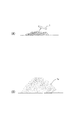
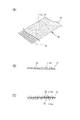
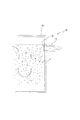
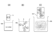
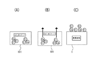
すなわち、例えば、図25(A)に示すように、原料としての木質チップ5をCaCl2 溶液100に浸漬してCaCl2 溶液100に接触させると、CaCl2 溶液100中のCaイオンとClイオンが木質チップ5に導入され、同図(C)に示すように、CaCl2 導入チップ101が得られる。これは、同図(B)に示すように、木質チップ5中の組織、特に通道組織にCaCl2 溶液100が染み込むからである。なお、原料の前処理(接触処理)に用いる前記CaCl2 溶液100の濃度としては、CaCl2 0.1重量%〜50重量%が好ましく、1重量%〜20重量%がコスト的により好ましい。0.1重量%を下回ると高い陰イオン吸着能は発現されず、50重量%を越えても陰イオン吸着能は向上しない。
That is, for example, as shown in FIG. 25 (A), the
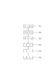
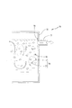
続いて、前記CaCl2 導入チップ101を、図26(A)に示すように炭化すると、同図(C)に示すように浄化材1が得られる。この炭化の過程では、CaCl2 導入チップ101中の有機物が熱で分解するのと同時に、ClイオンおよびCaイオンがCaCl2 導入チップ101の微細孔壁表面に析出する。このとき、同図(B)に示すように、ClイオンおよびCaイオンはCaCl2 導入チップ101の微細孔壁表面に微細で高分散状態に析出し、多くの官能基を微細孔壁の隅々から引き出す。その結果、同図(C)に示すように、Clイオンが、微細孔壁表面に引き出された多数の官能基に金属イオン(この場合Caイオン)を介してまたは直接結合された状態になると考えられる。
Subsequently, when the CaCl 2
なお、前記金属塩化物の含有量としては、前記炭化物内に結合される金属塩化物を灰分として2%〜25%含有させてあることが好ましい(請求項6)。炭化物内に結合される金属塩化物とは、炭化物内に単に付着している金属塩化物を除く金属塩化物であり、炭化物内に結合しているため、水や酸で洗い流した後に溶解せずに残留する金属塩化物をいう。2%を下回ると陰イオン吸着能が劣り、25%を上回っても陰イオン吸着能は向上しない傾向がある。 In addition, as content of the said metal chloride, it is preferable to contain 2 to 25% of the metal chloride couple | bonded in the said carbide | carbonized_material as ash (Claim 6). The metal chloride bonded in the carbide is a metal chloride except for the metal chloride that is simply adhered in the carbide. Since it is bonded in the carbide, it does not dissolve after washing with water or acid. The metal chloride remaining in If it is less than 2%, the anion adsorption ability is inferior, and even if it exceeds 25%, the anion adsorption ability tends not to be improved.
さらに、請求項5および6に係る発明において、前記炭化物を水および/または酸に接触させてあることが好ましい(請求項7)。なお、水および/または酸を前記炭化物に接触させる方法としては、水および/または酸の滴下、塗布、吹付け、噴霧などが可能であるが、前記炭化物を水および/または酸に浸漬させることが最も効率的である。
Furthermore, in the invention according to
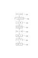
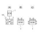
ここで、前記炭化物に水および/または酸を接触させることが好ましいことの理由は以下のように考えられる。すなわち、図25および図26に示したようにして得られた浄化材(CaCl2 炭)1を、図27(A)に示すように、例えば塩酸102や硫酸等の酸に浸漬(接触)させると、浄化材1に付着していた余分な金属塩化物の結晶が除去される。しかも、酸として塩酸102を用いた場合は、前記浄化材1の官能基と結合するClイオンが新たに増加し、同図(B)から同図(C)に示す状態に変わり、これらのことから、製造した陰イオン吸着能が高まって好ましい。なお、前記炭化物に塩酸102等の酸ではなく水を接触させた場合にも、浄化材1に付着していた余分な金属塩化物の結晶が除去され、陰イオン吸着能を高めることができる。
Here, the reason why it is preferable to contact the carbide with water and / or an acid is considered as follows. That is, the purification material (CaCl 2 charcoal) 1 obtained as shown in FIGS. 25 and 26 is immersed (contacted) in an acid such as
具体的には、前記金属塩化物としてCaCl2 またはBaCl2 が挙げられる(請求項8)。 Specifically, examples of the metal chloride include CaCl 2 and BaCl 2 .
上記排廃水処理用浄化材における原料植物としては、植物体であれば何でもよいが、天然繊維や木質材料の1種以上からなり、かつ炭化物が微細孔を有するものが好ましく、例えば、間伐材、伐採木、廃木材等全ての木質材料や麻等の天然繊維を挙げることができる。具体的には、吸水性の高い檜や杉等の針葉樹を例えば50mm以下(好適には10mm以下)のサイズにチップ化した木質チップを用いるのが好ましい。さらに、前記木質チップのほかに、竹、おが屑、籾殻、椰子、ビンロウジュ、ジュート、藁、ミカンやリンゴの皮、搾りかす等の農産廃棄物を用いてもよい。また、植物体の中で特に通道組織(道管,仮道管,または師管)を有する部分が好ましい。
前記原料を接触させる溶液として吸着対象陰イオンとイオン交換可能な陰イオン(例えば塩化物イオン等)をほとんど含まずカルシウムイオンを含む溶液(例えば石灰水や石灰乳等)を用いる場合、前記原料としては、カルシウムを導入した後炭化すると、その炭化物の微細孔に100nm以下の粒径のCa化合物が無数に形成されるようなものが好ましい。
また、吸着対象陰イオンとイオン交換可能な陰イオン(例えば塩化物イオン等)とカルシウムイオンを共に含む溶液(例えば塩化カルシウム溶液等)を用いる場合は、前記原料として、溶液に浸漬する際、溶液が染み込み易いようなものが望ましい。
The raw material plant in the wastewater treatment purification material may be anything as long as it is a plant body, but is preferably composed of one or more of natural fibers and woody materials, and a carbide having fine pores. Examples include all woody materials such as felled trees and waste wood, and natural fibers such as hemp. Specifically, it is preferable to use a wood chip in which conifers such as birch and cedar having high water absorption are chipped to a size of, for example, 50 mm or less (preferably 10 mm or less). Further, in addition to the wood chips, agricultural waste such as bamboo, sawdust, rice husk, coconut, areca, jute, straw, mandarin orange, apple skin, and pomace may be used. Moreover, the part which has a passage tissue (a canal, a temporary canal, or a master tube) in a plant body is especially preferable.
In the case of using a solution (for example, lime water or lime milk) that contains almost no anion (for example, chloride ion) ion-exchangeable with the anion to be adsorbed as the solution in contact with the material (for example, lime water or lime milk), Preferably, when carbon is introduced and then carbonized, countless Ca compounds having a particle size of 100 nm or less are formed in the fine pores of the carbide.
Moreover, when using the solution (for example, calcium chloride solution etc.) which contains both the anion (for example, chloride ion etc.) and calcium ion which can be ion-exchanged with an adsorption object anion, when immersing in a solution as said raw material, It is desirable for the material to easily penetrate.
また、第2発明の排廃水浄化方法においては、原料植物を炭化処理する前に、たとえば、当該原料植物にカルシウムイオンを含む溶液を接触させるなどして、原料植物にカルシウムを導入するようにしている。カルシウムイオンを含む溶液を原料植物に接触させる方法としては、前記溶液の滴下、塗布、吹付、噴霧などが可能であるが、原料植物を前記溶液に浸漬させることが最も効果的である。 Moreover, in the waste water purification method of 2nd invention, before carbonizing a raw material plant, it is made to introduce | transduce calcium to a raw material plant, for example by making the solution containing a calcium ion contact the said raw material plant. Yes. As a method of bringing a solution containing calcium ions into contact with the raw material plant, the solution can be dropped, applied, sprayed, sprayed, etc., but it is most effective to immerse the raw material plant in the solution.
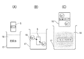
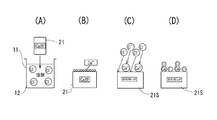
すなわち、前記原料をカルシウムイオンを含む溶液に浸漬させると、溶液が原料に染み込むことでCa導入チップを得ることができる。特に、カルシウムイオンを含む溶液としてアルカリ性の溶液を用いる場合、図11(A)に示すように、例えば、木質チップ5を石灰水18に浸漬させると、木質チップ5に石灰水18を接触させることができ、石灰水18中のCaが木質チップ5に導入され、図11(C)に示すように、Ca導入チップ16が得られる。これは、図11(B)に示すように、アルカリによって木質チップ5中の有機物が溶け出し、Caイオンが木質チップ5の成分と反応するからであると考えられる。そして、原料植物を前処理としての接触処理に用いる石灰水(または石灰乳)の濃度としては、Ca(OH)2 0.1重量%〜50重量%が好ましく、より好ましくは0.2重量%〜10重量%である。
That is, when the raw material is immersed in a solution containing calcium ions, a Ca-introduced chip can be obtained by the solution soaking into the raw material. In particular, when an alkaline solution is used as a solution containing calcium ions, as shown in FIG. 11A, for example, when the
前記Ca導入チップ16を、図12(A)に示すように炭化すると、図12(C)に示すようなCa導入炭化チップ(Ca導入炭)21が得られるが、この炭化時に、Ca導入チップ16(図12(B)参照)中の有機物が熱によって分解するのと同時に、CaイオンがCa導入チップ16の微細孔壁表面に析出する〔同図(C)参照〕と考えられる。この場合、図12(B)に示すように、CaイオンがCa導入チップ16の微細孔壁表面に析出してくるので、微細で高分散状態となることにより、多くの官能基を微細孔壁の隅々から引出すものと考えられる。
When the Ca-introduced
第1発明では、原料植物を炭化処理した後、その炭化物に酸溶液を接触させることによって、また、第2発明では、カルシウムイオンを含む溶液を接触させてカルシウム導入処理した原料植物を炭化処理した後、その炭化物に酸溶液を接触させることによって、それぞれ、炭化物の微細孔壁から引出した官能基に、吸着対象の陰イオンとイオン交換が可能な陰イオンを、直接またはカルシウムイオンを介して結合させている。 In the first invention, after carbonizing the raw material plant, an acid solution is brought into contact with the carbide, and in the second invention, the raw material plant subjected to calcium introduction treatment by contacting a solution containing calcium ions is carbonized. Then, by contacting the carbide with an acid solution, an anion capable of ion exchange with an anion to be adsorbed is bonded directly or via a calcium ion to the functional group extracted from the microporous wall of the carbide, respectively. I am letting.
また、本発明者らは、炭化処理過程で、温度および時間を制御することにより炭化物の官能基をより多く生成させることができることを見出した。つまり、第1発明のように、原料植物にCaを導入しない場合は、炭化処理の際の加熱温度による炭化物の官能基の生成量の差は少ない。一方、第2発明のように、原料植物に予めCaを導入してある場合は、650〜750℃の炭化処理温度を例えば1時間持続させた後、自然冷却させる場合の方が、約600℃および約800℃の炭化処理温度を1時間持続させた後、自然冷却させる場合に比べて、より多くの官能基が形成できることを本発明者らは確認した。 The inventors have also found that more functional groups of carbides can be generated by controlling the temperature and time during the carbonization process. That is, as in the first invention, when Ca is not introduced into the raw material plant, there is little difference in the generation amount of the functional group of the carbide depending on the heating temperature during the carbonization treatment. On the other hand, when Ca is previously introduced into the raw material plant as in the second invention, the carbonization temperature of 650 to 750 ° C. is maintained for, for example, 1 hour, and then the natural cooling is about 600 ° C. The present inventors have confirmed that more functional groups can be formed as compared with the case where the carbonization temperature of about 800 ° C. is maintained for 1 hour and then the mixture is naturally cooled.
特に、Caを導入した場合、電子顕微鏡で観察すると、650〜750℃の炭化処理温度で炭化させた炭化物では、Ca化合物の微粒子が炭化物の微細孔壁面に半ば析出して均一に分散している様子が観察された。一方、約600℃の炭化処理温度では、Ca化合物の微粒子の微細孔壁への析出が十分行われていない様子が観察された。また、約800℃の炭化処理温度では、Ca化合物の微粒子の微細孔壁への析出は見られるものの、欠落が多くなっている様子が観察された。このように、Caが炭化物の微細孔壁から官能基をできるだけ多く引出すために必要な炭化処理温度として約650〜750℃(最適は700℃)を挙げることができる。 In particular, when Ca is introduced, when observed with an electron microscope, in a carbide carbonized at a carbonization temperature of 650 to 750 ° C., fine particles of the Ca compound are half-deposited on the fine pore wall surface of the carbide and are uniformly dispersed. The situation was observed. On the other hand, at the carbonization temperature of about 600 ° C., it was observed that the Ca compound fine particles were not sufficiently deposited on the fine pore walls. Further, at the carbonization temperature of about 800 ° C., although the precipitation of Ca compound fine particles on the fine pore walls was observed, it was observed that the number of missing portions increased. Thus, about 650-750 degreeC (optimally 700 degreeC) can be mentioned as a carbonization process temperature required in order for Ca to draw out as many functional groups as possible from the fine pore wall of a carbide | carbonized_material.
特に、第2発明では、炭化処理対象の原料植物として、カルシウムイオンを含む溶液を用いてCaを導入したものを用い、これを炭化処理してCa導入炭21としている。例えば、図13(A)に示すように、Ca導入炭21をHCl溶液12に浸漬させると、同図(B)および(C)に示すように、Ca導入炭21の表面の官能基に結合したカルシウムイオンおよび前記官能基に塩化物イオン(Cl- )が結合して、同図(D)に示すように、前記官能基にCl- がカルシウムイオンを介してまたは直接結合している酸処理Ca導入炭21Sが得られると考えられる。なお、上記酸処理は、Ca導入炭21を酸溶液12に浸漬するのみでよいが、減圧下で行うのが好ましく、1330Pa〜13.3Paの圧力範囲で行うのが好ましい。
In particular, in the second invention, as a raw material plant to be carbonized, a plant into which Ca is introduced using a solution containing calcium ions is used, and this is carbonized to obtain a Ca-introduced
そして、原料植物の炭化処理は、400℃〜1000℃の温度範囲で行われることが好ましい(請求項9)。これは、炭化処理温度が400℃を下回ると、細孔が発達せず吸着材としての性能が劣り、前記温度が1000℃を超えると、炭素化が進みすぎることにより吸着特性が得られないからである。なお、炭化処理温度としてより好ましくは500℃〜900℃であり、最も好ましいのは650℃〜750℃である。 And it is preferable that the carbonization process of a raw material plant is performed in the temperature range of 400 to 1000 degreeC (Claim 9). This is because if the carbonization temperature is lower than 400 ° C., the pores do not develop and the performance as an adsorbent is inferior, and if the temperature exceeds 1000 ° C., adsorption characteristics cannot be obtained due to excessive carbonization. It is. The carbonization temperature is more preferably 500 ° C to 900 ° C, and most preferably 650 ° C to 750 ° C.
上記構成よりなる排廃水処理用浄化材は、優れた陰イオンの吸着性能を有する。そして、この排廃水処理用浄化材は、その製造時の排水処理などになんらの問題を生ずることはなく、極めて環境に優しく、また、安価に製造することができる。さらに、吸着対象の陰イオンを吸着した排廃水処理用浄化材から、吸着した陰イオンを除去するとともに、次の吸着対象の陰イオンとイオン交換が可能な陰イオンを前記除去した陰イオンに替えて結合させる(請求項10)ことにより、排廃水処理用浄化材を繰り返し再生使用することができる。なお、この発明の排廃水処理用浄化材で吸着可能な陰イオンは、炭化物の微細孔壁表面の官能基に直接またはカルシウムイオンを介して予め結合させてある陰イオンとイオン交換が可能な陰イオンであり、当然、前記炭化物の微細孔壁表面の官能基に直接またはカルシウムイオンを介して予め結合させてある陰イオン以外の陰イオンである。 The wastewater treatment purification material having the above-described configuration has excellent anion adsorption performance. The purification material for waste water treatment does not cause any problems in waste water treatment at the time of production, and is extremely environmentally friendly and can be produced at low cost. Furthermore, the adsorbed anion is removed from the purification material for waste water treatment that adsorbs the anion to be adsorbed, and the anion that can exchange ions with the next anion to be adsorbed is replaced with the removed anion. (Claim 10), the waste water treatment purification material can be repeatedly recycled. The anion that can be adsorbed by the purification material for wastewater treatment of the present invention can be ion-exchanged with an anion previously bonded to a functional group on the surface of the fine pore wall of the carbide directly or via calcium ion. Naturally, it is an anion other than an anion previously bonded directly or via a calcium ion to a functional group on the surface of the microporous wall of the carbide.
そして、第4発明の排廃水浄化方法は、請求項1〜10のいずれかに記載の排廃水処理用浄化材を用いて排廃水を浄化することを特徴とする(請求項11)。前記排廃水処理用浄化材は、そのままの形状で使用することもできるが、粒体状または粉体状に加工することができる。したがって、例えば、粒体状の排廃水処理用浄化材を、適宜のメッシュを有する網籠やメッシュ状袋体に収納して排廃水処理用浄化体とし、この排廃水処理用浄化体を排廃水と十二分に接触しうる状態に設置することにより、前記下水中に含まれる陰イオンが確実に吸着される。また、粉体状にした場合は、これを不織布に付着させるなどして排廃水処理用浄化体としてもよい。さらに、排廃水の通水路に流亡防止用メッシュを設け、この通水路内に排廃水処理用浄化材を収容して排廃水処理用浄化体としてもよい。 And the waste-water purification method of 4th invention is characterized by purifying waste-water using the waste-water-treatment purification material in any one of Claims 1-10 (Claim 11). The waste water treatment purification material can be used as it is, but can be processed into a granular form or a powder form. Therefore, for example, the granular wastewater treatment purification material is stored in a mesh bag or mesh bag having an appropriate mesh to form a wastewater treatment purification body, and this wastewater treatment purification body is used as wastewater. The anion contained in the sewage is surely adsorbed by being installed in a state where it can be sufficiently in contact with. Moreover, when powdered, it may be used as a waste water treatment purifier by attaching it to a nonwoven fabric. Furthermore, a drainage prevention mesh may be provided in the drainage wastewater passage, and the wastewater treatment purification material may be accommodated in the passageway by containing the wastewater treatment purification material.
第5発明の排廃水処理装置は、排廃水流路に請求項1〜11のいずれかに記載の排廃水処理用浄化材を設け、排廃水を浄化するように構成してあることを特徴としている(請求項12)。この排廃水処理装置を、半導体工場、石油精製工場、医薬品・農薬・機能性薬品などの各種化学工場、鉄鋼・鋼材の製造工場、金属精錬工場、製紙工場、繊維工場、植物工場、食品工場からの廃水や、各家庭・合併浄化槽・集落単位における生活排水などに適用することにより、排廃水中の陰イオンを確実に吸着させることができる。
A waste water treatment apparatus according to a fifth aspect of the present invention is characterized in that the waste waste water treatment purification material according to any one of
また、前記排廃水処理用浄化材の吸着能を再生するための再生部と、排廃水処理用浄化材を再生部に移動させる浄化材取出し機構とを有することが好ましい(請求項13)。すなわち、排廃水処理用浄化材を再生部において定期的に再生することにより、その吸着能を低下させることがなく、それだけ排廃水に含まれる陰イオンを効果的に吸着することができる。 In addition, it is preferable to have a regeneration unit for regenerating the adsorption capacity of the waste water treatment purification material and a purification material take-out mechanism for moving the waste water treatment purification material to the regeneration unit. In other words, by periodically regenerating the waste water treatment purification material in the regeneration unit, it is possible to effectively adsorb the anions contained in the waste water without reducing the adsorption capacity.
本発明の排廃水処理用浄化材は、所望の陰イオン吸着性能を有し、また、原料植物を炭化処理して得られる炭化物に陰イオン吸着特性を持たせた炭素材料からなるか、または前記炭素材料を含むので環境にやさしいものとなっているとともに、安価に製造することができる。 The purification material for wastewater treatment of the present invention has a desired anion adsorption performance, and is composed of a carbon material obtained by carbonizing a raw material plant so as to have anion adsorption characteristics. Since it contains a carbon material, it is environmentally friendly and can be manufactured at low cost.
そして、上記排廃水処理用浄化材において、原料植物をカルシウム導入処理した後炭化する場合には、陰イオン交換樹脂と同等あるいは陰イオン交換樹脂よりも優れた陰イオン吸着特性を持つ陰イオン吸着炭素材料を得ることができる。 And, in the above purification material for wastewater treatment, when the raw material plant is carbonized after calcium introduction treatment, anion adsorption carbon having anion adsorption characteristics equivalent to or better than anion exchange resin Material can be obtained.
また、上記排廃水処理用浄化材を用いる排廃水浄化方法および排廃水処理装置により、排廃水中の陰イオンが確実に吸着される。また、排廃水処理用浄化材には、単なる木炭等、従来から使用されている浄化材を併用してもよい。 In addition, anions in the wastewater are reliably adsorbed by the wastewater purification method and the wastewater treatment apparatus using the wastewater treatment purification material. Moreover, you may use together the purification material conventionally used, such as a mere charcoal, in the purification material for waste water treatment.
図1〜図3は、本発明の第1実施例を示す。まず、図1(A)は、本発明の排廃水処理用浄化材(以下、単に浄化材という)1の一例を示すもので、この実施例では、長さが10mm程度のチップ状に形成されている。また、図1(B)は、前記チップ状の浄化材1適宜径の粒体(ペレット)1aに形成した例を示す。
1 to 3 show a first embodiment of the present invention. First, FIG. 1A shows an example of a waste water treatment purification material (hereinafter simply referred to as a purification material) 1 of the present invention. In this embodiment, the purification material is formed in a chip shape having a length of about 10 mm. ing. FIG. 1 (B) shows an example in which the chip-shaped
前記浄化材1を製造する装置および方法について、図2および図3を参照しながら説明する。図2は、浄化材1を製造する装置の一例を概略的に示すもので、この図において、5は原料植物で、この実施例では木質チップである。この木質チップ5は、例えば、吸水性の高い檜や杉等の針葉樹を50mm以下(好適には10mm以下)の適宜のサイズにチップ化したものである。6は木質チップ5を炭化処理する炭化処理炉で、その内部には適宜の熱源7によって加熱される炭化炉本体8が収容されている。この炭化炉本体8の導入部8aから供給された木質チップ5は、適宜の温度(後述する)、適宜の時間(後述する)加熱することにより炭化され、炭化チップ(炭化物)9として排出部8bから排出される。
An apparatus and a method for manufacturing the
そして、図2において、10は前記炭化チップ9を酸処理する装置で、例えば、処理槽11内に適宜濃度のHClが酸溶液12として収容されている。なお、13は処理槽11内に設けられる攪拌用羽根13で、モータ(図示していない)によって回転駆動され、処理槽11内の酸溶液12の濃度を均一になるように攪拌するものである。
In FIG. 2,
また、図2において、14は前記酸処理、中和処理、中和後水洗い処理(以下、酸処理等という)後の炭化チップ(酸処理炭化チップ)9Sを乾燥させる乾燥機で、この乾燥機14には炭化処理炉6から排出される排熱が供給されるようにしてある。
In FIG. 2, 14 is a dryer for drying the carbonized chips (acid-treated carbonized chips) 9S after the acid treatment, neutralization treatment, and post-neutralization water washing treatment (hereinafter referred to as acid treatment). 14 is supplied with exhaust heat discharged from the
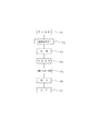
上記装置を用いて、原料植物5から浄化材1を得る手順の一例を、図3をも参照しながら説明すると、まず、檜や杉等の針葉樹を10mm以下の適宜のサイズにチップ化した木質チップ5を用意する(ステップS11)。
An example of a procedure for obtaining the
前記木質チップ5は、炭化処理炉6の炭化炉本体8に供給され、400℃〜1000℃の温度範囲で1時間程度加熱され炭化処理される(ステップS12)。これによって、炭化チップ9が得られる。
The
前記炭化チップ9は、酸処理装置10に供給され、処理槽11内の0.01mol/L〜20mol/Lに調整された酸溶液12に浸漬され、酸処理される(ステップS13)。なお、炭化チップ9の酸溶液12への浸漬処理は、炭化チップ9に酸溶液12を接触させる処理の一例を示すものであり、この他にも炭化チップ9に対する酸溶液12の滴下、塗布、吹付、噴霧などが可能である。
The
酸処理後の酸処理炭化チップ9Sは、一般的には乾燥機14において乾燥処理される(ステップS14)。この場合、酸処理炭化チップ9Sをそのまま乾燥機14に送るようにしてもよいが、適宜のアルカリ溶液に浸漬するなどして中和処理したり、さらには、中和処理後に水洗いしてもよい。なお、酸処理炭化チップ9Sを湿潤状態で使用するときは、乾燥処理をしないこともある。
The acid-treated
そして、前記乾燥処理後の酸処理炭化チップ9Sは、加工を施さずにそのままの形状で使用することもできるが、適宜の加工機を用いて適宜径の粒体(ペレット)1aやより細かな粉体1bに形成される(ステップS15)。そして、例えば、金網よりなる網籠内に前記ペレット状の浄化材1aを多数収容することにより、排廃水処理用浄化体が得られる(ステップS16)。
The acid-treated
上述の第1実施例では、原料植物(例えば、木質チップ)5を炭化処理し、この炭化処理によって得られる炭化物(例えば、炭化チップ)9を酸溶液12に浸漬処理して前記炭化物9に陰イオン吸着特性を持たせるようにしていたが、原料植物5として、カルシウム導入処理したものを用いるようにしてもよい。以下、これを第2実施例として、図4および図5を参照しながら説明する。
In the first embodiment described above, the raw material plant (for example, wood chips) 5 is carbonized, and the carbide (for example, carbonized chips) 9 obtained by this carbonization treatment is immersed in the
まず、図4は、浄化材1を製造する装置の他の例を概略的に示すもので、この図において、図2に示した符号と同一符号は同一物である。この実施例における装置が図2に示した第1実施例の装置と大きく異なる点を説明すると、15は木質チップ5にCaを導入処理し、Ca導入チップ16とするための装置で、例えば、処理槽17内にカルシウムイオンを含む溶液18を収容してなるものであり、この実施形態では、前記カルシウムイオンを含む溶液18は適宜濃度の石灰水(または石灰乳)である。なお、19は処理槽17内に設けられる攪拌用羽根で、モータ(図示していない)によって回転駆動され、処理槽17内のカルシウムイオンを含む溶液18を濃度が均一になるように攪拌するものである。
First, FIG. 4 schematically shows another example of an apparatus for producing the
また、図4において、20は前記Ca導入処理装置15において得られるCa導入チップ16を乾燥させる乾燥機で、この乾燥機20には炭化処理炉6から排出される排熱が供給されるようにしてある。
In FIG. 4,
上記装置を用いて、原料植物5から浄化材1を得る手順の一例を、図5をも参照しながら説明すると、まず、檜や杉等の針葉樹を10mm以下の適宜のサイズにチップ化した木質チップ5を用意する(ステップS21)。
An example of a procedure for obtaining the
前記木質チップ5をCa導入処理装置15の処理槽17内の5重量%に調整されたカルシウムイオンを含む溶液18内に例えば、3時間以上浸漬する。この場合、溶液18を木質チップ5へ充分染み込ませるため、或いはカルシウムイオンを木質チップ5の成分と充分反応させるために、木質チップ5の浸漬中に、攪拌羽根19を回転させることが好ましい。これによって、Caイオンが木質チップ5の成分と充分反応することができ、木質チップ5にCaが導入されたCa導入チップ16が得られる(ステップS22)。なお、前記Ca導入処理は、石灰乳を用いた方が処理効率がよい。また、木質チップ5のカルシウムイオンを含む溶液18への浸漬処理は、木材チップ5にカルシウムイオンを含む溶液18を接触させる処理の一例を示すものであり、この他にも木材チップ5に対するカルシウムイオンを含む溶液18の滴下、塗布、吹付、噴霧などが可能である。そして、溶液18としては、石灰水や石灰乳に代えて、塩化カルシウム溶液や酢酸カルシウム溶液を用いることもできる。
The
前記Ca導入処理後のCa導入チップ16は、乾燥機20に送られて乾燥処理される(ステップS23)。
The
前記乾燥処理後のCa導入チップ16は、炭化処理炉6の炭化炉本体8に供給され、700℃の処理温度で、1時間程度加熱して炭化処理される(ステップS24)。これによって、Ca導入炭化チップ(Ca導入炭)21が得られる。
The dried Ca-introduced
前記Ca導入チップ21は、酸処理装置10に供給され、処理槽11内の例えば5mol/Lに調整された酸溶液12に浸漬され、酸処理される(ステップS25)。この場合、攪拌羽根13を回転させるのが好ましく、これによって、Ca導入チップ21の微細孔壁表面のCaCO3 が酸によって溶解するのを促進させるとともに、塩化物イオンおよびカルシウムイオンをCa導入チップ21の微細孔壁表面の官能基と充分反応させることができ、所望のCa導入酸処理炭化チップ21Sが得られる。なお、Ca導入チップ21の酸溶液12への浸漬処理は、Ca導入チップ21に酸溶液12を接触させる処理の一例を示すものであり、この他にもCa導入チップ21に対する酸溶液12の滴下、塗布、吹付、噴霧などが可能である。
The
前記酸処理後のCa導入酸処理炭化チップ21Sは、一般的には乾燥機14において乾燥処理される(ステップS26)。この場合、Ca導入酸処理炭化チップ21Sをそのまま乾燥機14に送るようにしてもよいが、適宜のアルカリ溶液に浸漬するなどして中和処理したり、さらには、中和処理後に水洗いしてもよいことはいうまでもない。
The Ca-introduced acid-treated
そして、前記乾燥処理後のCa導入酸処理炭化チップ21Sは、加工を施さずにそのままの形状で使用することもできるが、適宜の加工機を用いて適宜径の粒体(ペレット)やより細かな粉体に形成される(ステップS27)。そして、例えば、金網よりなる網籠内にペレット状の浄化材1aを多数収容することにより、排廃水処理用浄化体が得られる(ステップS28)。
Then, the Ca-introduced acid-treated
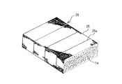
図6は図1に示したチップ状の浄化材1や図2または図4に示したペレット状の浄化材1を適宜径の粒状(ペレット)1aに形成したものを、例えば、外観視直方体形状の網籠25に収容して排廃水処理用浄化体26とした例を示している。ここで、網籠25は、容易に化学物質に侵されたり、容易に溶出しないプラスチックやステンレス鋼など化学的に安定な素材よりなり、粒体状の浄化材1aが網目から外部に簡単に抜け出たりしない程度の細かい目合いを有している。なお、図中、25aは補強用線材である。また、詳細には、図示していないが、網籠25には開閉・ロック自在の扉を備えた開口が形成されており、浄化材1aを交換または補充することができるように構成されている。
FIG. 6 shows a chip-shaped
上記排廃水処理用浄化体25は、図6に例示したものに限られるものではなく、例えば、図7に示すように、例えば、ポリエチレンなどのような耐腐蝕性素材からなる網袋27内に図1に示したチップ状の浄化材1や図2または図4に示したペレット状の浄化材1aを多数収容してマット状の排廃水処理用浄化体28を構成してもよい。この場合、網袋27の開口(図示していない)を開閉自在できるようにして、浄化材1または1aの充填・取り出しを容易に行えるようにしておくことが望ましい。
The waste
また、図8は、他の排廃水処理用浄化体30の例を概略的に示すものである。図8(A)に示す排廃水処理用浄化体30は、前記チップ状の浄化材1(適宜径のペレット1aまたは粉体1bに形成したもの)を担持するように構成した透水性シート(例えば、不織布シート)31と、この不織布シート31を補強するように不織布シート31に重合する高強度のネット32とを有している。また、本実施例の排廃水処理用浄化体30は長尺の帯状であり、例えば環状の帯を形成する(詳細は後述する)ように構成してある。なお、不織布シート31に浄化材のペレット1aまたは粉体1bを担持する場合は、浄化材のペレット1aまたは粉体1bを不織布シート31の原料に混入するようにして排廃水処理用浄化体30を構成することができる。また、浄化材1を後述の接着剤などを用いて不織布シート31に固定してもよい。
FIG. 8 schematically shows another example of the
図8(B)に示す排廃水処理用浄化体30は、不織布シート31の一方の面全体に前記チップ状の浄化材1(例えばペレット状の浄化材1a)を適宜の接着剤33を用いて貼着するように保持する。なお、図8(C)に示すように、チップ状の浄化材1(ペレット状の浄化材1a)は不織布シート31の表裏両面に固着してあってもよい。
The waste water
ここで、前記浄化材1の硝酸性窒素、亜硝酸性窒素およびフッ素の吸着性能について説明する。まず、硝酸性窒素および亜硝酸性窒素の吸着性能の試験方法および試験結果について説明すると、以下の通りである。
Here, the adsorption performance of nitrate nitrogen, nitrite nitrogen and fluorine of the
〔硝酸性窒素および亜硝酸性窒素の吸着性能について〕
〔試験方法〕
硝酸性窒素および亜硝酸性窒素の濃度が50mg/L(50ppm)の硝酸溶液および亜硝酸溶液50mL(標準液)をそれぞれ5つ用意し、
(1)木質チップ5を700℃で炭化させた比較例に用いる木炭9を200mg、
(2)木質チップ5を700℃で炭化させた木炭を1mol/LのFeCl3 溶液に浸漬させた後、水洗いした比較例に用いる塩化鉄木炭200mg、
(3)木質チップ5を700℃で炭化させた木炭を5mol/LのHCl溶液に浸漬させた後、水洗いした酸処理木炭9Sを200mg、
(4)木質チップ5を5重量%の石灰水18に浸漬した後700℃で炭化させた木炭を5mol/LのHCl溶液に浸漬させたCa導入酸処理木炭21Sを200mg、
(5)比較例に用いる陰イオン交換樹脂200mgの5つのサンプルを、それぞれ対応する標準液に入れ、例えば200rpm、20℃の条件下で、10時間振とう後、硝酸溶液および亜硝酸溶液中の硝酸性窒素の濃度および亜硝酸性窒素の濃度をそれぞれ測定し、吸着量を計算した。
[Adsorption performance of nitrate nitrogen and nitrite nitrogen]
〔Test method〕
Prepare 5 nitric acid solutions and 50 mL (standard solution) of nitric acid solution with 50 mg / L (50 ppm) concentration of nitrate nitrogen and nitrite nitrogen,
(1) 200 mg of
(2) 200 mg of iron chloride charcoal used for the comparative example washed with water after the charcoal obtained by carbonizing the
(3) After immersing the charcoal obtained by carbonizing the
(4) 200 mg of Ca-introduced acid-treated
(5) Five samples of 200 mg of an anion exchange resin used in the comparative example were put in the corresponding standard solutions, respectively, shaken for 10 hours under the conditions of, for example, 200 rpm and 20 ° C., and then in a nitric acid solution and a nitrous acid solution. The concentration of nitrate nitrogen and the concentration of nitrite nitrogen were measured, and the amount of adsorption was calculated.
〔結果〕
図9は、上記各サンプルの硝酸性窒素および亜硝酸性窒素吸着能の比較を表す。
(1)の700℃炭化の木炭9は、硝酸性窒素および亜硝酸性窒素をほとんど吸着しないのに対して、(2)の塩化鉄木炭は、硝酸性窒素および亜硝酸性窒素をそれぞれ2.75mg/gおよび2.35mg/g吸着した。また、(3)の酸処理木炭9Sは、硝酸性窒素および亜硝酸性窒素をそれぞれ2.50mg/gおよび2.20mg/g吸着した。(5)の陰イオン交換樹脂は、硝酸性窒素および亜硝酸性窒素をそれぞれ10.80mg/gおよび10.00mg/g吸着した。一方、木質チップ5を石灰水18に浸漬した後炭化し、続いて、HCl溶液に浸漬させてなる(4)のCa導入酸処理木炭21Sは、硝酸性窒素および亜硝酸性窒素をそれぞれ10.75mg/gおよび9.80mg/g吸着し、(5)の陰イオン交換樹脂と同等以上の吸着能力を示した。
〔result〕
FIG. 9 shows a comparison of the nitrate nitrogen and nitrite nitrogen adsorption capacities of the above samples.
The
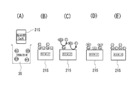
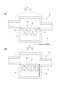
そして、前記Ca導入酸処理木炭21Sが例えば硝酸イオンを吸着するメカニズムは、以下のように考えられる。図14(A)に示すように、Ca導入酸処理木炭21Sを硝酸溶液35に漬けると、Ca導入酸処理木炭21Sの表面の官能基にカルシウムイオンを介してまたは直接官能基に結合した塩化物イオン(同図(B)参照)と硝酸溶液35中の硝酸イオンが交換され(同図(C)参照)、硝酸イオンがCa導入酸処理木炭21Sに吸着される(同図(D)参照)。そして、同図(E)は、同図(D)に示すCa導入酸処理木炭21Sを例えば濃いKCl(またはNaCl)溶液に漬けたときの変化を示す。すなわち、吸着された硝酸イオンはKCl(またはNaCl)溶液で再度、塩化物イオンと硝酸イオンを交換させて再生可能となる。以下、この再生について説明する。
The mechanism by which the Ca-introduced acid-treated
《再生試験》
〔試験方法〕
前記硝酸性窒素吸着試験を行った後の酸処理木炭9SまたはCa導入酸処理木炭21Sの試料を1mol/LのKCl(またはNaCl)溶液で洗浄し、さらに水洗いした。続いて、標準液を交換して硝酸性窒素濃度が50mg/Lの硝酸溶液50mLを用意し、水洗いした200mgの前記試料の1回目の再生試験を行った。すなわち、前記試料を硝酸溶液に入れ、例えば200rpm、20℃の条件下で、10時間振とう後、前記硝酸溶液中の硝酸性窒素濃度を測定し、吸着量を計算する1回目の再生試験を前記試料を用いて行った。
《Regeneration test》
〔Test method〕
A sample of acid-treated
次に、1回目の再生試験で用いた前記試料を1mol/LのKCl(またはNaCl)溶液で洗浄し、さらに水洗いした。続いて、標準液を交換して硝酸性窒素濃度が50mg/Lの硝酸溶液50mLを用意し、前記水洗いした200mgの前記試料の再生試験を行った。すなわち、前記試料を、硝酸溶液50mLに入れ、例えば200rpm、20℃の条件下で、10時間振とう後、前記硝酸溶液中の硝酸性窒素濃度を測定し、吸着量を計算する2回目の再生試験を前記試料を用いて行った。この処理をあと2回繰り返した。 Next, the sample used in the first regeneration test was washed with a 1 mol / L KCl (or NaCl) solution and further washed with water. Subsequently, the standard solution was replaced to prepare 50 mL of a nitric acid solution having a nitrate nitrogen concentration of 50 mg / L, and a regeneration test of the washed 200 mg of the sample was performed. That is, the sample is put in 50 mL of a nitric acid solution, shaken for 10 hours, for example, under conditions of 200 rpm and 20 ° C., then the concentration of nitrate nitrogen in the nitric acid solution is measured and the amount of adsorption is calculated. The test was performed using the sample. This process was repeated two more times.
〔結果〕
酸処理木炭9Sによる硝酸性窒素の吸着量
初回…2.5mg/g
再生1回目…2.5mg/g
再生2回目…2.4mg/g
再生3回目…2.5mg/g
Ca導入酸処理木炭21Sによる硝酸性窒素の吸着量
初回…10.8mg/g
再生1回目…10.6mg/g
再生2回目…10.9mg/g
再生3回目…10.7mg/g
〔result〕
Amount of nitrate nitrogen adsorbed by acid-treated
The first reproduction ... 2.5mg / g
Second playback: 2.4 mg / g
3rd regeneration ... 2.5mg / g
Adsorption amount of nitrate nitrogen by Ca-introduced acid-treated
The first reproduction ... 10.6mg / g
Second playback: 10.9mg / g
3rd regeneration ... 10.7mg / g
以上のことから、使用した酸処理木炭9SおよびCa導入酸処理木炭21Sをそれぞれ濃いKCl(またはNaCl)溶液で洗浄し、さらに水洗いすることにより、再生することが分かった。すなわち、硝酸性窒素吸着試験で硝酸性窒素(陰イオン)を吸着した酸処理木炭9SおよびCa導入酸処理木炭21Sをそれぞれ、KCl(またはNaCl)溶液で洗浄し、さらに水洗いすることにより、硝酸性窒素吸着試験で吸着した硝酸性窒素(陰イオン)が除去されて、除去された硝酸性窒素(陰イオン)に替えてCl- を結合させることにより、酸処理木炭9SおよびCa導入酸処理木炭21Sがそれぞれ再生されることが分かった。つまり、一度使用した酸処理木炭9SおよびCa導入酸処理木炭21Sをそれぞれ使用後にその都度洗浄と水洗いを行うことにより、複数回使用できることが確認された。なお、亜硝酸性窒素を吸着した場合でも、陰イオン吸着炭素材料として酸処理木炭9SおよびCa導入酸処理木炭21Sをそれぞれ使用しても、再生する原理は同じである。
From the above, it was found that the acid-treated
〔フッ素吸着性能について〕
〔試験方法〕
フッ化物イオン濃度が50mg/Lの溶液50mL(標準液)を用意し、
(1)木質チップ5を700℃で炭化させた比較例に用いる木炭9Sを100mg、
(2)木質チップ5を700℃で炭化させた木炭を1mol/LのFeCl3 溶液に浸漬させた後、水洗いした比較例に用いる塩化鉄木炭100mg、
(3)木質チップ5を700℃で炭化させた木炭を5mol/LのHCl溶液に浸漬させた後、水洗いした酸処理木炭9Sを100mg、
(4)木質チップ5を5重量%の石灰水に浸漬した後700℃で炭化させた木炭を5mol/LのHCl溶液に浸漬させたCa導入酸処理木炭21Sを100mg、
(5)比較例に用いる陰イオン交換樹脂100mgの5つのサンプルを、それぞれ対応する標準液に入れ、例えば200rpm、20℃の条件下で、10時間振とう後、前記溶液中のフッ化物イオン濃度をそれぞれ測定し、吸着量を計算した。
[Fluorine adsorption performance]
〔Test method〕
Prepare 50 mL (standard solution) of a solution having a fluoride ion concentration of 50 mg / L,
(1) 100 mg of
(2)
(3) After immersing charcoal obtained by carbonizing the
(4) 100 mg of Ca-introduced acid-treated
(5) Five samples of 100 mg of the anion exchange resin used in the comparative example are placed in the corresponding standard solutions, and after shaking for 10 hours under the conditions of, for example, 200 rpm and 20 ° C., the fluoride ion concentration in the solution Was measured, and the amount of adsorption was calculated.
〔結果〕
図10は、上記各サンプルのフッ化物イオン吸着能の比較を表す。
(1)の700℃炭化の木炭は、フッ化物イオンをほとんど吸着しないのに対して、(2)の塩化鉄木炭は、7.50mg/gのフッ化物イオンを吸着した。また、(3)の酸処理木炭9Sは、5.00mg/gのフッ化物イオンを吸着した。(5)の陰イオン交換樹脂は、8.50mg/gのフッ化物イオンを吸着した。一方、木質チップ5を石灰水に浸漬した後炭化し、続いて、HCl溶液に浸漬させてなる(4)のCa導入酸処理木炭21Sは、19.00mg/gのフッ化物イオンを吸着し、(5)の陰イオン交換樹脂を大きく超える吸着能力を示した。
〔result〕
FIG. 10 shows a comparison of fluoride ion adsorption capacities of the above samples.
The 700 ° C. charcoal (1) hardly adsorbs fluoride ions, whereas the iron chloride charcoal (2) adsorbs 7.50 mg / g fluoride ions. Moreover, the acid-treated
《再生試験》
〔試験方法〕
次に、前記フッ素吸着試験を行った後の酸処理木炭9SまたはCa導入酸処理木炭21Sの試料を1mol/Lの塩酸(または硫酸)で洗浄し、さらに水洗いした。続いて、標準液を交換してフッ化物イオン濃度が50mg/Lの溶液50mLを用意し、前記水洗いした200mgの前記試料の1回目の再生試験を行った。すなわち、前記試料を前記溶液に入れ、例えば200rpm、20℃の条件下で、10時間振とう後、前記溶液中のフッ化物イオン濃度を測定し、吸着量を計算する1回目の再生試験を前記試料を用いて行った。
《Regeneration test》
〔Test method〕
Next, a sample of acid-treated
次に、1回目の再生試験で用いた前記試料を1mol/Lの塩酸(または硫酸)で洗浄し、さらに水洗いした。続いて、標準液を交換してフッ化物イオン濃度が50mg/Lの前記溶液50mLを用意し、前記水洗いした200mgの前記試料の再生試験を行った。すなわち、前記試料を、前記溶液50mLに入れ、例えば200rpm、20℃の条件下で、10時間振とう後、前記溶液中のフッ化物イオン濃度を測定し、吸着量を計算する2回目の再生試験を前記試料を用いて行った。この処理をあと2回繰り返した。 Next, the sample used in the first regeneration test was washed with 1 mol / L hydrochloric acid (or sulfuric acid) and further washed with water. Subsequently, the standard solution was exchanged to prepare 50 mL of the solution having a fluoride ion concentration of 50 mg / L, and a regeneration test of the washed 200 mg of the sample was performed. That is, the second regeneration test in which the sample is placed in 50 mL of the solution and shaken for 10 hours under the conditions of, for example, 200 rpm and 20 ° C., and then the fluoride ion concentration in the solution is measured and the adsorption amount is calculated. Was performed using the sample. This process was repeated two more times.
〔結果〕
酸処理木炭9Sによるフッ化物イオンの吸着量
初回…2.5mg/g
再生1回目…2.5mg/g
再生2回目…2.4mg/g
再生3回目…2.5mg/g
Ca導入酸処理木炭21Sによるフッ化物イオンの吸着量
初回…18.7mg/g
再生1回目…18.2mg/g
再生2回目…18.9mg/g
再生3回目…18.6mg/g
〔result〕
Adsorption amount of fluoride ion by acid-treated
The first reproduction ... 2.5mg / g
Second playback: 2.4 mg / g
3rd regeneration ... 2.5mg / g
Adsorption amount of fluoride ion by Ca-introduced acid-treated
The first reproduction ... 18.2mg / g
Second playback: 18.9 mg / g
3rd regeneration ... 18.6mg / g
以上のことから、使用した酸処理木炭9SおよびCa導入酸処理木炭21Sをそれぞれ濃い塩酸(または硫酸)で洗浄し、さらに水洗いすることにより、再生することが分かった。すなわち、フッ素吸着試験でフッ化物イオン(陰イオン)を吸着した酸処理木炭9SおよびCa導入酸処理木炭21Sをそれぞれ、塩酸(または硫酸)で洗浄し、さらに水洗いすることにより、フッ素吸着試験で吸着したフッ化物イオン(陰イオン)が除去されて、除去されたフッ化物イオン(陰イオン)に替えてCl- (またはSO4 2-)を結合させることにより、酸処理木炭9SおよびCa導入酸処理木炭21S(陰イオン吸着炭素材料)がそれぞれ再生することが分かった。つまり、一度使用した酸処理木炭9SおよびCa導入酸処理木炭21Sをそれぞれ使用後にその都度洗浄と水洗いを行うことにより、複数回使用できることが確認された。
From the above, it was found that the acid-treated
上述のように、本発明の浄化材1は、硝酸性窒素、亜硝酸性窒素およびフッ素等の陰イオンの吸着性能に優れる。また、吸着対象の陰イオンを吸着した使用済みの浄化材1(1a,1b)から、吸着した陰イオンが除去されるととともに、次の吸着対象の陰イオンとイオン交換が可能な陰イオンを前記除去した陰イオンに替えて結合させることにより、浄化材1(1a,1b)を再生でき、この再生処理した浄化材1(1a,1b)を繰り返し使用することができる。このような浄化材1をたとえば排廃水の配水管の途中に形成される排廃水の処理用の浄化装置など実際の排廃水処理装置に適用した例について、以下に説明する。
As described above, the
図15および図16は、本発明の第3実施例を示す。そして、図15は排廃水処理装置40の一例を概略的に示すものである。
15 and 16 show a third embodiment of the present invention. FIG. 15 schematically shows an example of the waste
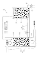
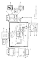
図15において、41は例えば半導体工場、石油精製工場、医薬品・農薬・機能性薬品などの各種化学工場、鉄鋼・鋼材の製造工場、金属精錬工場、製紙工場、繊維工場、植物工場、食品工場からの廃水や、各家庭・合併浄化槽・集落単位における生活排水などの排廃水流路、42はこの排廃水流路41を流れる排廃水を導入可能に構成された有底筒状の吸着塔(以下、吸着部という)、43はこの吸着部42の底部を構成するメッシュ板である。この吸着部42には図1に示したチップ状の浄化材1や図2または図4に示したペレット状の浄化材1aを収容している。
In FIG. 15,
本実施例の排廃水流路41は吸着部42の上端に排廃水を供給する上流側流路41aと吸着部42の下端に連通連結して吸着部42内を流れる排廃水を浄化材1(1a)によって浄化したのちに下水として排出する下流側流路41bとを有している。前記吸着部42およびメッシュ板43は例えば化学物質によって容易に腐蝕したり何らかの成分が溶出することがないプラスチックやステンレス綱などの化学的に安定な素材よりなり、メッシュ板43の網目は、チップ状の浄化材1aが外部に簡単に抜け出たりしない程度の細かい目合いを有している。つまり、本例の排廃水処理装置40では、排廃水流路41a,41bの間に排廃水を貯蔵する槽(排廃水槽)である吸着部42を設け、この吸着部42に浄化材1(1a)を収容することにより、排廃水を浄化する例を示している。
In the present embodiment, the
44は再生液45を収容可能に構成された有底筒状の再生塔(以下、再生部という)、46は再生部44内の再生液45を排出可能に構成された排出流路、47は吸着部42の下部と再生部44を連通連結する連通流路、48は連通流路47に設けられた開閉バルブである。そして、吸着部42に収容された浄化材1(1a)が陰イオンを十分に吸着して、その吸着能力が低下したときに、開閉バルブ48を開いて予め空にしてある再生部へと流動させる。すなわち、本実施例の排廃水処理装置40は吸着部42内の浄化材1(1a)を再生部45に移動させるための排出流路46と開閉バルブ48とからなる浄化材取出し機構49を備えている。なお、浄化材取出し機構49を用いて再生部44に流動させる浄化材1(1a)は、吸着部42に収容された浄化材1(1a)の全量とするか一部とするかは適宜定めることができる。
44 is a bottomed tubular regeneration tower (hereinafter referred to as a regeneration section) configured to accommodate the
再生液45は浄化材1(1a)による吸着対象が硝酸イオンである場合、例えば塩化カリウム(KCl)等を用いることができる。また、浄化材1(1a)による吸着対象がフッ素である場合、再生液45として塩酸(HCl)等を用いる。すなわち、再生部44に収容する再生液45は吸着対象に合わせて適宜選択されるものである。そして、再生が完了した浄化材1(1a)は必要に応じて水洗いし、これを吸着部42に戻すことができる。
For example, potassium chloride (KCl) can be used as the regenerating
一方、再生処理後の再生液45は排出流路46に設けた下部バルブ46aを開くことにより回収し、これを別途処理する。使用後の再生液45の処理は、浄化材1(1a)による吸着対象がフッ素である場合、炭酸カルシウム(CaCO3 )と反応させてフッ化カルシウム(CaF2 )とし、沈殿槽を用いてCaF2 を沈殿除去して処分する。なお、沈殿槽で除去しきれなかったフッ化物イオンは別の浄化材1(1a)で吸着し、この浄化材1(1a)を再生せずに燃焼させることによりフッ化カルシウムとして処分することができる。当然、フッ素を吸着した浄化材1(1a)を吸着部42から再生部45に移動させた時点で、再生処理を行わずに浄化材1(1a)を取り出し、焼却してフッ化カルシウムとして処分することもできる。吸着対象がフッ素である場合、吸着部42の前方に沈殿槽を、その沈殿槽で予め炭酸カルシウムを加えて反応させ、大部分のフッ化物イオンをフッ化カルシウムとして沈殿除去するのが望ましい。沈殿槽で除去しきれないフッ化物イオンを吸着部42にて吸着し、フッ素の排出基準を満たす排廃水を排出できることとなる。
On the other hand, the regenerated
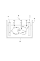
図16は前記再生液45の処理方法を説明する図である。図16に示すように、浄化材1(1a)による吸着対象が硝酸イオンである場合には、使用済みの再生液45を電気分解によって分解処分することができる。
FIG. 16 is a view for explaining a processing method of the regenerating
図16において、50は前記再生液45を収容可能に構成された分解処理槽、51は分解処理槽50に収容される陽極、52は陰極、53は両極51,52に分解に必要な電力を供給する電源である。すなわち、分解処理槽50に使用済みの再生液45を収容し両極51,52間に電圧を印加することにより、陽極51の近傍で塩化物イオン(Cl- )が酸化力の高い次亜塩酸(ClO- )に転化し、陰極52の近傍で硝酸塩(NO3 - )がアンモニア(NH3 )に還元され、次いで、陽極で発生した次亜塩酸(ClO- )と再生液45中のアンモニアおよび陰極52で生じたアンモニア(NH3 )が反応し、無害な窒素ガス(N2 )へと転化する。
In FIG. 16, 50 is a decomposition treatment tank configured to be able to contain the regenerating
図17は、本発明の第4実施例である排廃水処理装置60の一例を概略的に示すものである。
FIG. 17 schematically shows an example of the waste
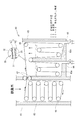
図17において、61は例えば半導体工場、石油精製工場、医薬品・農薬・機能性薬品などの各種化学工場、鉄鋼・鋼材の製造工場、金属精錬工場、製紙工場、繊維工場、植物工場、食品工場からの廃水や、各家庭・合併浄化槽・集落単位における生活排水などの排廃水流路、62は排廃水流路61に連通する水平断面四角形に形成された配管(以下、吸着部という)、63は吸着部62に隣接するように配置された2つの液溜め部63a,63bを有する再生部、64,65は各液溜め部63a,63bの下端部に設けた排出流路、66は吸着部62内に配置された複数のローラ、67は吸着部62の内外を隔てる位置に配置された一対のローラ、68は再生部63内の各所に配置された複数のローラである。
In FIG. 17,
そして、図8を用いて説明した帯状の排廃水処理用浄化体30を各ローラ66〜68に掛けた状態でこのローラ66〜68を一方向に回転させることにより、排廃水処理用浄化体30に含まれる浄化材1(1a,1b)が吸着部62内に収容された状態と再生部63内に収容された状態に切り換え可能に循環するように構成してある。すなわち、本実施例における浄化材取出し機構は各ローラ66〜68である。
Then, the waste water
また、本実施例の排廃水処理装置60において、液溜め部63a,63bにはそれぞれ水およびKCl溶液を収容してあり、吸着部62内で排廃水処理用浄化体30が吸着した硝酸イオンをKClによって再生し、水洗いした後に再び吸着部62に戻す一連の動作を連続して行なうことができるように構成してある。なお、浄化材1(1a,1b)による吸着対象がフッ素である場合は、液溜め部63bにHClを収容する。
Further, in the waste
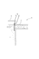
図18は、本発明の第5実施例である排廃水処理装置70の一例を概略的に示すものである。図18(A)において、71は例えば各家庭・合併浄化槽・集落単位における生活排水などの排廃水流路、72は上流側の排廃水流路71aと下流側の排廃水流路71bの間に配置した排廃水溜め部(以下、吸着部)、73は図6に示す排廃水処理用浄化体26に取り付けたフロートである。本実施例のように構成することにより、網籠25内の浄化材1aの全部が排廃水の水面よりも下位に位置しこれと接するようにしてある。
FIG. 18 schematically shows an example of the waste
前記排廃水処理用浄化体26は、種々の形態で設置することができる。例えば、図18(B)に示すように、排廃水溜め部72内に支持部材74を立設し、この支持部材74に排廃水処理用浄化体26を水平に固定してもよい。さらには、図示を省略するが、排廃水処理用浄化体26の大きさを排廃水溜め部72の内部のほゞ全体を占める程度に大きく形成してもよい。何れの場合にも、排廃水溜め部72が排廃水流路71a,71bの間に形成された排廃水槽を構成すると共に、浄化材1(1a)を収容してなる処理部として機能して排廃水を浄化することができる。
The waste
また、図19に示すように、排廃水流路71内に排廃水処理用浄化体26を挿入設置してもよい。この場合、排廃水処理用浄化体26が排廃水流路流路71内を容易に移動しないように固定するのが好ましい。この場合、排廃水流路71が浄化材1(1a)を収容してなる処理部として機能して排廃水を浄化する。
In addition, as shown in FIG. 19, the waste
図20は、本発明の排廃水処理装置70の別の変形例を示している。図20に示す排廃水処理装置75は図1に示したチップ状の浄化材1を多数、前記排廃水流路71に連通する排廃水溜め部72内に投入し、これを水流によって泳動させてもよい。この場合、排廃水溜め部72の下流側の排廃水流路71への出口に浄化材1の流出を防止する網体76を設ける必要がある。
FIG. 20 shows another modification of the waste
また、図3または図5に示したペレット状の浄化材1aを、図21に示すように、排廃水36を通過させることのできる透水性の不織布よりなる袋体77内に複数収容して比較的小さい排廃水処理用浄化体78とし、図20に示したのと同様に、排廃水溜め部72内に投入してもよい、なお、図21において、79は排廃水処理用浄化体78の流出を防止するため、排廃水溜め部72の下流側の排廃水流路71への出口に設けられる網体である。
Further, as shown in FIG. 21, a plurality of pellet-shaped
そして、図22に示すように、図8に示したシート状の排廃水処理用浄化体30を、適宜のケース79内に積層して排廃水処理用浄化体80とし、これを、例えば、排廃水溜め部72内の下流側の排廃水流路71への出口に設けるようにしてもよい。つまり、図20〜22に示す本実施例の場合も、排廃水溜め部72が排廃水流路71a,71bの間に形成された排廃水槽を構成し、この排廃水槽72が浄化材1(1a,1b)を収容する処理部として機能して排廃水を浄化する。
Then, as shown in FIG. 22, the sheet-shaped wastewater
なお、図18〜22に示す排廃水処理装置70は、各家庭・合併浄化槽・集落単位における生活排水などの排廃水流路71に配置される例を示しているが、この同じ構造を例えば半導体工場、石油精製工場、医薬品・農薬・機能性薬品などの各種化学工場、鉄鋼・鋼材の製造工場、金属精錬工場、製紙工場、繊維工場、植物工場、食品工場からの廃水が流れる排廃水流路に設けることも可能であることは言うまでもない。
In addition, although the
上述の第2実施例では、原料植物5としてカルシウム導入処理したものを用いているが、原料植物5として、金属塩化物導入処理したものを用いるようにしてもよい。以下、これを第6実施例として、図23および図24を参照しながら説明する。
In the second embodiment described above, the
まず、図23は、浄化材1を製造する装置のさらに他の例を概略的に示すもので、この図において、図4に示した符号と同一符号は同一物である。そして、図23に示すように、前記木質チップ5は、適宜濃度の金属塩化物溶液(この実施の形態ではCaCl2 溶液)91を収容した処理槽92に送られ、この処理槽92内において木質チップ5に対する金属塩化物(この実施の形態ではCaCl2 )の導入処理が行われ、金属塩化物導入チップ93が形成される。なお、94は処理槽92内に設けられる攪拌用羽根で、モータ(図示していない)によって回転駆動され、処理槽92内の液等を攪拌する際に用いられる。なおここで、金属塩化物溶液に対して、Ca(OH)2 を僅かに加えておくことが、陰イオン吸着能を向上させる上で好ましい。
First, FIG. 23 schematically shows still another example of an apparatus for producing the
上記のようにして得られた金属塩化物導入チップ93は、乾燥機20によって乾燥処理された後、炭化処理炉6に送られ、炭化処理される。なお、前記乾燥機20は、炭化処理炉6から排出される排熱を前記乾燥処理に利用するように構成されている。
The metal
そして、金属塩化物導入チップ93は、導入部8aを経て前記炭化炉本体8内に供給され、適宜の温度(後述する)および適宜の時間(後述する)の加熱により炭化され、浄化材1として排出部8bから炭化炉本体8外に排出される。
The metal
その後、前記浄化材1は、水またはHCl溶液(塩酸)96を収容した処理槽97に送られ、この処理槽97内において浄化材1の水またはHCl溶液96に対する接触(浸漬)処理が行われる。なお、98は処理槽97内に設けられる攪拌用羽根で、モータ(図示していない)によって回転駆動され、処理槽97内の液等を攪拌する際に用いられる。酸への接触処理を行った後に水への接触処理を行うこともあり、またその逆の手順で行ってもよい。
Thereafter, the
続いて、前記浄化材1は、乾燥機14に送られ、乾燥処理された後、適宜径の粒体(ペレット)1aやより細かな粉体1bに形成される。なお、前記乾燥機14は、炭化処理炉6から排出される排熱を前記乾燥処理に利用するように構成されている。
Subsequently, the
次に、図23に示した装置を用いて、原料植物5から浄化材1を得る手順の一例を、図23および図24を参照しながら詳細に説明する。まず、檜や杉等の針葉樹を10mm以下の適宜のサイズにチップ化した木質チップ5を用意する(ステップT1)。
Next, an example of a procedure for obtaining the
続いて、前記木質チップ5を処理槽92内の1〜20重量%に調整されたCaCl2 溶液91内に例えば、3時間以上浸漬する。この木質チップ5の浸漬中に、攪拌羽根94を回転させることが好ましい。これによって、CaCl2 溶液91が木質チップ5に染み込むことができ、木質チップ5にCaイオンおよびClイオンが導入された金属塩化物導入チップ93が得られる(ステップT2)。
Subsequently, the
そして、前記金属塩化物導入チップ93は、乾燥機20に送られて乾燥処理される(ステップT3)。
Then, the metal
その後、前記金属塩化物導入チップ93は、炭化処理炉6の炭化炉本体8に供給され、400℃〜1000℃の温度範囲(この実施の形態では700℃)で1時間程度加熱され炭化処理される(ステップT4)。これによって、浄化材1が得られる。
Thereafter, the metal
前記浄化材1は、処理槽97に供給され、処理槽97内の0.01mol/L〜11mol/L(例えば5mol/L)に調整されたHCl溶液96に浸漬処理される(ステップT5)。この場合、攪拌羽根98を回転させるのが好ましく、これによって、浄化材1内に残留する余分な金属塩化物(CaCl2 )の結晶を除去することができるとともに、塩化物イオンをさらに付加させることができ、所望の浄化材1が得られる。
The said
そして、前記浸漬処理後の浄化材1は、一般的には乾燥機14において乾燥処理される(ステップT6)。この場合、浄化材1をそのまま乾燥機14に送るようにしてもよいが、適宜のアルカリ溶液に浸漬するなどして中和処理したり、さらには、中和処理後に水洗いしてもよい。なお、浄化材1を湿潤状態で使用するときは、乾燥処理をしないこともある。
And the purification | cleaning
そして、前記乾燥処理後の浄化材1は、チップ状のまま使用することもできるが、この実施例では適宜の加工機を用いて適宜径の粒体(ペレット)1aやより細かな粉体1bに形成してある(ステップT7)。
And although the
なお、前記浄化材1は、上記ステップT1からステップT7までが全て同一工場内で行われて製造されるものに限られない。例えば、他の工場等にて上記ステップT1〜T7のうちのあるステップまで製造されている場合、途中のステップから始めて浄化材1を製造すればよい。
In addition, the said
なお、上記第6実施例では、金属塩化物として、最も高性能な陰イオン吸着炭素材料が得られるCaCl2 を挙げているが、BaCl2 やMnCl2 等でもよい。 In the sixth embodiment, as the metal chloride, CaCl 2 from which the highest-performance anion-adsorbing carbon material is obtained is exemplified, but BaCl 2 , MnCl 2 or the like may be used.
また、上記第6実施例では、処理槽97内において浄化材1のHCl溶液96に対する接触処理を行っているが、HCl溶液96に代えて水を用いてもよい。この場合、塩化物イオンの付加は行われず、浄化材1内に残留する余分な金属塩化物の結晶を除去するのみとなる。
Further, in the sixth embodiment, the contact treatment with the
さらに、上記実施の形態では、金属塩化物導入チップ93を炭化処理炉6にて炭化処理して浄化材1を得た後、処理槽97へと送っているが、処理槽97へと送らなくてもよい。この場合、前記浄化材1を乾燥機14に送る必要がないので、浄化材1の製造方法は、上記ステップT5,T6が省かれたものとなる。また、この場合、浄化材1の製造方法としては、ステップT1〜T4で終了してもよいし、その後ステップT7を行ってもよい。
Furthermore, in the above embodiment, the metal
次に、第6実施例の浄化材1の硝酸性窒素および亜硝酸性窒素の吸着性能を調べるために行った試験について説明する。硝酸性窒素および亜硝酸性窒素の吸着性能の試験方法および試験結果について説明すると、以下の通りである。
Next, a test conducted for examining the adsorption performance of nitrate nitrogen and nitrite nitrogen of the
まず、以下に示す計七つのサンプル(1)〜(7)をそれぞれ200mgずつ2組用意した。すなわち、
(1)木質チップ5を700℃で1時間加熱し炭化させて得られた木炭
(2)木質チップ5を700℃で1時間加熱し炭化させ、その後、1mol/LのFeCl3 溶液に浸漬し水洗いして得られた塩化鉄木炭
(3)陰イオン交換樹脂
(4)木質チップ5を10重量%のBaCl2 溶液に浸漬した後700℃で1時間加熱し炭化させて得られたBaCl2 炭
(5)木質チップ5を10重量%のBaCl2 溶液に浸漬した後700℃で1時間加熱し炭化させ、その後、5mol/LのHCl溶液に浸漬処理して得られたHCl処理BaCl2 炭
(6)木質チップ5を10重量%のCaCl2 溶液に浸漬した後700℃で1時間加熱し炭化させて得られたCaCl2 炭
(7)木質チップ5を10重量%のCaCl2 溶液に浸漬した後700℃で1時間加熱し炭化させ、その後、5mol/LのHCl溶液に浸漬処理して得られたHCl処理CaCl2 炭
の計七つのサンプルを2組用意した。なお、(4)〜(7)のサンプルは上記浄化材1に相当するものであり、(1)〜(3)のサンプルは浄化材1と比較するためのものである。
First, two sets of 200 mg each were prepared for a total of seven samples (1) to (7) shown below. That is,
(1) Charcoal obtained by heating and carbonizing the
そして、一方の組の各サンプルを、硝酸性窒素の濃度が50mg/L(50ppm)の硝酸性窒素溶液50mL(第1標準液)に個別に投入し、また、他方の組の各サンプルを、亜硝酸性窒素の濃度が50mg/L(50ppm)の亜硝酸性窒素溶液50mL(第2標準液)に個別に投入した。その後、200rpm、20℃の条件下で、10時間振とう後、第1標準液中の硝酸性窒素の濃度および第2標準液中の亜硝酸性窒素の濃度をそれぞれ測定し、各サンプルによる硝酸性窒素および亜硝酸性窒素の吸着量を計算した。 Then, each sample of one set is individually put into 50 mL (first standard solution) of a nitrate nitrogen solution having a nitrate nitrogen concentration of 50 mg / L (50 ppm), and each sample of the other set is The nitrite nitrogen concentration was individually added to 50 mL (second standard solution) of nitrite nitrogen solution having a concentration of 50 mg / L (50 ppm). Then, after shaking for 10 hours under the conditions of 200 rpm and 20 ° C., the concentration of nitrate nitrogen in the first standard solution and the concentration of nitrite nitrogen in the second standard solution were measured, respectively. The amount of adsorbed nitrogen and nitrite nitrogen was calculated.
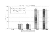
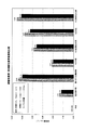
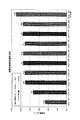
図29は、上記試験によって得られた各サンプルの硝酸性窒素吸着能および亜硝酸性窒素吸着能の比較結果を表す。なお、この図では、各サンプルの硝酸性窒素・亜硝酸性窒素吸着量を一対の棒グラフで示しており、左側の棒グラフが硝酸性窒素吸着量、右側の棒グラフが亜硝酸性窒素吸着量を示している。この図に示す結果から、本発明のサンプルはいずれも高い硝酸性窒素吸着能および亜硝酸性窒素吸着能を持つことがわかる。さらに、(4)のBaCl2 炭と(5)のHCl処理BaCl2 炭の硝酸性窒素および亜硝酸性窒素の吸着量を比較し、また、(6)のCaCl2 炭と(7)のHCl処理CaCl2 炭の硝酸性窒素および亜硝酸性窒素の吸着量を比較することにより、浄化材1の硝酸性窒素・亜硝酸性窒素吸着能をより高めるためには、浄化材1をHCl溶液に浸漬する処理(HCl処理)を行ったほうがよいことがわかる。しかし、HCl処理を行わなくても十分に高い硝酸性窒素・亜硝酸性窒素吸着能を持った浄化材1が得られ、この場合には、HCl溶液の接触処理を行わない分だけ低いコストで浄化材1を製造することができる。
FIG. 29 shows a comparison result of nitrate nitrogen adsorption ability and nitrite nitrogen adsorption ability of each sample obtained by the above test. In this figure, the amount of nitrate nitrogen and nitrite nitrogen adsorption of each sample is shown as a pair of bar graphs. The left bar graph shows the nitrate nitrogen adsorption amount, and the right bar graph shows the nitrite nitrogen adsorption amount. ing. From the results shown in this figure, it can be seen that all the samples of the present invention have high nitrate nitrogen adsorption ability and nitrite nitrogen adsorption ability. Further, the adsorption amounts of nitrate nitrogen and nitrite nitrogen of (4) BaCl 2 charcoal and (5) HCl-treated BaCl 2 charcoal were compared, and (6) CaCl 2 charcoal and (7) HCl adsorbed. In order to further enhance the nitrate nitrogen / nitrite nitrogen adsorption capacity of the
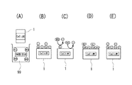
ここで、前記浄化材1が例えば硝酸イオンを吸着するのは、図28(A)に示すように、浄化材(CaCl2 炭)1を硝酸溶液99に浸漬すると、浄化材1の表面の官能基にCaイオンを介してまたは直接結合されたClイオン(同図(B)参照)と硝酸溶液99中のNO3 イオンが交換され(同図(C)参照)、NO3 イオンが浄化材1に吸着される(同図(D)参照)からであると考えられる。
Here, the
また、図28(E)は、NO3 イオンを吸着して図28(D)に示す状態となった浄化材1を、高濃度の塩化物溶液(例えばKClやNaClの金属塩化物溶液、またはHCl溶液)に浸漬した後の状態を示す。すなわち、浄化材1に吸着されたNO3 イオンは、塩化物溶液によってClイオンと交換され、これにより浄化材1が再生され、NO3 イオンなどの陰イオンを吸着可能な状態となる。すなわち、第6実施例の浄化材1は、上記製造方法により常に新たに得られるものに限られず、前記製造方法により得られ、陰イオン(例えばNO3 イオン)を吸着した浄化材1から、吸着した陰イオン(NO3 イオン)が除去されるとともに、次の吸着対象の陰イオン(例えばNO3 イオン)とイオン交換が可能な陰イオン(この実施の形態ではClイオン)を前記除去した陰イオン(NO3 イオン)に替えて結合させることによって得られたもの(すなわち再生されたもの)でもよい。また、上記塩化物溶液に代えて硫酸を用いた場合は、NO3 イオンは、上記Clイオンに代えてSO4 イオンとイオン交換されることとなる。
FIG. 28E shows a
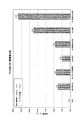
次に、上記ステップT2において木質チップ5を浸漬する金属塩化物溶液(CaCl2 溶液)91の濃度が、製造後の浄化材1の陰イオン吸着能に与える影響を調べるために行った試験について述べる。上記試験は、木質チップ5をCaCl2 溶液91に浸漬した後、700℃で1時間の加熱により炭化し、水洗いして得た浄化材1を、硝酸性窒素の濃度が50mg/L(50ppm)の硝酸性窒素溶液50mL(標準液)に投入し、前記浄化材1の硝酸性窒素の吸着能を調べたもので、前記CaCl2 溶液61として、濃度が1重量%、3重量%、5重量%、7重量%、10重量%、12重量%、14重量%、17重量%、20重量%のものが用いられた。また、比較のために、木質チップ5を10重量%のCaCl2 溶液91に浸漬した後、700℃で1時間の加熱により炭化し、HCl処理して得た浄化材1の硝酸性窒素の吸着能についても調べた。上記試験の結果を図30に示す。
Next, the concentration of metal chloride solution (CaCl 2 solution) 91 soaking the
図30に示す結果から明らかなように、浄化材1の陰イオン吸着能はCaCl2 溶液の濃度に比例して高くなるわけではなく、コスト面等から考えれば、10重量%程度とすることが最も好ましいといえる。また、この図30に示す結果からも、浄化材1の陰イオン吸着能をより高めるためには、浄化材1をHCl処理したほうがよいことがわかる。
As is clear from the results shown in FIG. 30, the anion adsorption capacity of the
次に、硝酸性窒素の吸着に使用された第6実施例の浄化材1をKCl(またはNaCl)溶液によって再生し、再生された浄化材1の硝酸性窒素吸着能を調べるために行った再生試験について説明する。
Next, the
まず、浄化材1として、木質チップ5を10重量%のCaCl2 溶液に浸漬した後700℃で1時間加熱し炭化させて得られたCaCl2 炭を200mg用意した。そして、このCaCl2 炭を、硝酸性窒素の濃度が50mg/L(50ppm)の硝酸性窒素溶液50mL(標準液)に投入し、200rpm、20℃の条件下で、10時間振とう後、前記標準液中の硝酸性窒素の濃度を測定し、前記CaCl2 炭による硝酸性窒素の吸着量を計算した(初回)。
First, 200 mg of CaCl 2 charcoal obtained by immersing the
続いて、前記CaCl2 炭を1mol/LのKCl(またはNaCl)溶液で洗浄し、さらに水洗いして再生した。その後、新たに用意した標準液(すなわち、硝酸性窒素の濃度が50mg/Lの硝酸性窒素溶液50mL)に再生したCaCl2 炭を投入し、200rpm、20℃の条件下で、10時間振とう後、前記標準液中の硝酸性窒素の濃度を測定し、前記CaCl2 炭による硝酸性窒素の吸着量を計算した。そして、このCaCl2 炭の再生から硝酸性窒素の吸着量の計算までの処理を計3回行った(再生一回目〜三回目)。
Subsequently, the CaCl 2 charcoal was washed with a 1 mol / L KCl (or NaCl) solution and further regenerated by washing with water. Thereafter, the regenerated CaCl 2 charcoal is added to a newly prepared standard solution (that is, a
上記再生試験の結果、すなわち、CaCl2 炭による硝酸性窒素の吸着量は、
初回 …9.5mg/g
再生一回目…9.0mg/g
再生二回目…9.1mg/g
再生三回目…8.8mg/g
であった。以上のことから、硝酸性窒素の吸着に使用した浄化材1(CaCl2 炭)は、濃いKCl(またはNaCl)溶液で洗浄しさらに水洗いすれば再生することが確認された。これは、硝酸性窒素を吸着したCaCl2 炭をKCl(またはNaCl)溶液で洗浄し、さらに水洗いすることにより、CaCl2 炭から硝酸性窒素が除去され、この除去された硝酸性窒素に代わってCl- が官能基に結合されるためであると考えられる。また、上記再生試験の結果から、浄化材1(CaCl2 炭)は、KCl(またはNaCl)溶液を用いた洗浄と水洗いとを行うことにより再生させれば、硝酸性窒素の吸着に複数回使用することができることも確認された。なお、前記浄化材1(CaCl2 炭)を亜硝酸性窒素の吸着に使用した場合でも、再生する原理は同じである。
As a result of the regeneration test, that is, the adsorption amount of nitrate nitrogen by CaCl 2 charcoal is
First time: 9.5mg / g
The first regeneration ... 9.0mg / g
Second regeneration: 9.1 mg / g
The third regeneration ... 8.8mg / g
Met. From the above, it was confirmed that the purification material 1 (CaCl 2 charcoal) used for the adsorption of nitrate nitrogen was regenerated by washing with a concentrated KCl (or NaCl) solution and further with water. This is because the nitrate nitrogen is removed from the CaCl 2 charcoal by washing the CaCl 2 charcoal adsorbing the nitrate nitrogen with a KCl (or NaCl) solution and then washing with water. This is thought to be because Cl - is bonded to a functional group. Moreover, from the result of the regeneration test, the purification material 1 (CaCl 2 charcoal) can be used multiple times for adsorption of nitrate nitrogen if it is regenerated by washing with KCl (or NaCl) solution and washing with water. It was also confirmed that it could be done. Even when the purification material 1 (CaCl 2 charcoal) is used for adsorption of nitrite nitrogen, the principle of regeneration is the same.
次に、第6実施例の浄化材1として、木質チップ5を10重量%のCaCl2 溶液に浸漬した後700℃で1時間加熱し炭化させ、その後、5mol/LのHCl溶液に浸漬処理して得られたHCl処理CaCl2 炭を用い、このHCl処理CaCl2 炭について上記と同様に再生試験を行った結果を示す。
Next, as the
上記再生試験の結果、すなわち、HCl処理CaCl2 炭による硝酸性窒素の吸着量は、
初回 …11.0mg/g
再生一回目…11.0mg/g
再生二回目…10.8mg/g
再生三回目…10.8mg/g
であった。以上のことから、炭化後にHCl溶液に浸漬処理して得られる浄化材1(HCl処理CaCl2 炭)についても、硝酸性窒素の吸着に使用後、濃いKCl(またはNaCl)溶液で洗浄し、さらに水洗いすることにより、再生することが確認された。また、HCl溶液への浸漬処理によって向上したHCl処理CaCl2 炭の硝酸性窒素吸着能は、KCl(またはNaCl)溶液を用いた洗浄と水洗いとを行ってHCl処理CaCl2 炭を繰り返し再生させても持続すること(向上したままであること)が確認された。
As a result of the regeneration test, that is, the adsorption amount of nitrate nitrogen by the HCl-treated CaCl 2 charcoal,
First time ... 11.0mg / g
The first regeneration ... 11.0mg / g
Second regeneration: 10.8mg / g
The third regeneration ... 10.8mg / g
Met. From the above, purifying material 1 (HCl-treated CaCl 2 charcoal) obtained by immersing in HCl solution after carbonization is also washed with concentrated KCl (or NaCl) solution after use for adsorption of nitrate nitrogen, Regeneration was confirmed by washing with water. Further, the nitrate nitrogen adsorption ability of the HCl-treated CaCl 2 charcoal improved by the immersion treatment in the HCl solution is obtained by repeatedly regenerating the HCl-treated CaCl 2 charcoal by washing with KCl (or NaCl) solution and washing with water. Has also been confirmed to remain (still improved).
次に、第6実施例の浄化材1のフッ化物イオンの吸着性能を調べるために行った試験について説明する。まず、この試験を行うために、上述した硝酸性窒素および亜硝酸性窒素の吸着性能の試験で用いた計七つのサンプル(1)〜(7)をそれぞれ50mgずつ1組用意した。そして、各サンプルを、フッ化物イオン濃度が50mg/L(50ppm)の溶液50mL(標準液)に個別に投入し、200rpm、20℃の条件下で、10時間振とう後、標準液中のフッ化物イオンの濃度をそれぞれ測定し、各サンプルによるフッ化物イオンの吸着量を計算した。
Next, a test conducted for examining the fluoride ion adsorption performance of the
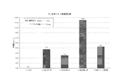
図31は、上記試験によって得られた各サンプルのフッ化物イオン吸着能の比較結果を表す。この図に示す結果から、本発明のサンプルはいずれも高いフッ化物イオン吸着能を持つことがわかる。さらに、(4)のBaCl2 炭と(5)のHCl処理BaCl2 炭のフッ化物イオンの吸着量を比較し、また、(6)のCaCl2 炭と(7)のHCl処理CaCl2 炭のフッ化物イオンの吸着量を比較することにより、浄化材1のフッ化物イオン吸着能をより高めるためには、浄化材1をHCl溶液に浸漬する処理(HCl処理)を行ったほうがよいことがわかる。しかし、HCl処理を行わなくても十分に高いフッ化物イオン吸着能を持った浄化材1が得られ、この場合には、HCl溶液の接触処理を行わない分だけ低いコストで浄化材1を製造することができる。
FIG. 31 shows a comparison result of fluoride ion adsorption ability of each sample obtained by the above test. From the results shown in this figure, it can be seen that all the samples of the present invention have high fluoride ion adsorption ability. Furthermore, the adsorption amounts of fluoride ions of (4) BaCl 2 charcoal and (5) HCl-treated BaCl 2 charcoal were compared, and (6) CaCl 2 charcoal and (7) HCl-treated CaCl 2 charcoal were compared. By comparing the adsorption amount of fluoride ions, it is understood that it is better to perform a treatment (HCl treatment) in which the
次に、フッ化物イオンの吸着に使用された上記浄化材1を塩酸(または硫酸)によって再生し、再生された浄化材1のフッ化物イオン吸着能を調べるために行った再生試験について説明する。
Next, a regeneration test performed to regenerate the
まず、浄化材1として、木質チップ5を10重量%のCaCl2 溶液に浸漬した後700℃で1時間加熱し炭化させて得られたCaCl2 炭を200mg用意した。そして、このCaCl2 炭を、フッ化物イオンの濃度が50mg/L(50ppm)の溶液50mL(標準液)に投入し、200rpm、20℃の条件下で、10時間振とう後、前記標準液中のフッ化物イオンの濃度を測定し、前記CaCl2 炭によるフッ化物イオンの吸着量を計算した(初回)。
First, 200 mg of CaCl 2 charcoal obtained by immersing the
続いて、前記CaCl2 炭を1mol/Lの塩酸(または硫酸)で洗浄し、さらに水洗いして再生した。その後、新たに用意した標準液(すなわち、フッ化物イオンの濃度が50mg/Lの溶液50mL)に再生したCaCl2 炭を投入し、200rpm、20℃の条件下で、10時間振とう後、前記標準液中のフッ化物イオンの濃度を測定し、前記CaCl2 炭によるフッ化物イオンの吸着量を計算した。そして、このCaCl2 炭の再生からフッ化物イオンの吸着量の計算までの処理を計3回行った(再生一回目〜三回目)。 Subsequently, the CaCl 2 charcoal was washed with 1 mol / L hydrochloric acid (or sulfuric acid) and further regenerated by washing with water. Thereafter, the regenerated CaCl 2 charcoal was added to a newly prepared standard solution (that is, 50 mL of a solution having a fluoride ion concentration of 50 mg / L), shaken at 200 rpm and 20 ° C. for 10 hours, The concentration of fluoride ions in the standard solution was measured, and the adsorption amount of fluoride ions by the CaCl 2 charcoal was calculated. Then, the processing up to the calculation of the adsorption amount of fluoride ions from the reproduction of the CaCl 2 charcoal was carried out three times (reproducing first time - third time).
上記再生試験の結果、すなわち、CaCl2 炭によるフッ化物イオンの吸着量は、
初回 …22.5mg/g
再生一回目…22.4mg/g
再生二回目…21.7mg/g
再生三回目…21.9mg/g
であった。以上のことから、フッ化物イオンの吸着に使用した浄化材1(CaCl2 炭)は、濃い塩酸(または硫酸)で洗浄しさらに水洗いすれば再生することが確認された。これは、フッ化物イオンを吸着したCaCl2 炭を塩酸(または硫酸)で洗浄し、さらに水洗いすることにより、CaCl2 炭からフッ化物イオンが除去され、この除去されたフッ化物イオンに代わってCl- (またはSO4 2- )が官能基に結合されるためであると考えられる。また、上記再生試験の結果から、浄化材1(CaCl2 炭)は、塩酸(または硫酸)を用いた洗浄と水洗いとを行うことにより再生させれば、フッ化物イオンの吸着に複数回使用することができることも確認された。
As a result of the regeneration test, that is, the adsorption amount of fluoride ions by CaCl 2 charcoal,
First time ... 22.5mg / g
The first reproduction… 22.4mg / g
Second regeneration: 21.7 mg / g
The third regeneration ... 21.9mg / g
Met. From the above, it was confirmed that the purification material 1 (CaCl 2 charcoal) used for the adsorption of fluoride ions was regenerated by washing with concentrated hydrochloric acid (or sulfuric acid) and further with water. This is because the fluoride ions are removed from the CaCl 2 charcoal by washing the CaCl 2 charcoal on which the fluoride ions have been adsorbed with hydrochloric acid (or sulfuric acid) and then washing with water, and instead of the removed fluoride ions, Cl - (Or SO 4 2- ) is considered to be bonded to the functional group. Further, from the result of the regeneration test, the purification material 1 (CaCl 2 charcoal) is used for adsorption of fluoride ions multiple times if it is regenerated by washing with hydrochloric acid (or sulfuric acid) and washing with water. It was also confirmed that it was possible.
次に、第6実施例の浄化材1として、木質チップ5を10重量%のCaCl2 溶液に浸漬した後700℃で1時間加熱し炭化させ、その後、5mol/LのHCl溶液に浸漬処理して得られたHCl処理CaCl2 炭を用い、このHCl処理CaCl2 炭について上記と同様に再生試験を行った結果を示す。
Next, as the
上記再生試験の結果、すなわち、HCl処理CaCl2 炭によるフッ化物イオンの吸着量は、
初回 …32.0mg/g
再生一回目…31.5mg/g
再生二回目…31.4mg/g
再生三回目…31.2mg/g
であった。以上のことから、炭化後にHCl溶液に浸漬処理して得られる浄化材1(HCl処理CaCl2 炭)についても、フッ化物イオンの吸着に使用後、塩酸(または硫酸)溶液で洗浄し、さらに水洗いすることにより、再生することが確認された。また、HCl溶液への浸漬処理によって向上したHCl処理CaCl2 炭のフッ化物イオン吸着能は、塩酸(または硫酸)を用いた洗浄と水洗いとを行ってHCl処理CaCl2 炭を繰り返し再生させても持続すること(向上したままであること)が確認された。
As a result of the regeneration test, that is, the adsorption amount of fluoride ions by the HCl-treated CaCl 2 charcoal,
First time… 32.0mg / g
First reproduction: 31.5mg / g
Second regeneration: 31.4mg / g
The third regeneration ... 31.2mg / g
Met. From the above, purifying material 1 (HCl-treated CaCl 2 charcoal) obtained by immersion treatment in HCl solution after carbonization is also used for adsorption of fluoride ions, then washed with hydrochloric acid (or sulfuric acid) solution, and further washed with water. By doing so, it was confirmed that it was reproduced. Further, the fluoride ion adsorption ability of the HCl-treated CaCl 2 charcoal improved by the immersion treatment in the HCl solution can be obtained by repeatedly regenerating the HCl-treated CaCl 2 charcoal by washing with hydrochloric acid (or sulfuric acid) and washing with water. It was confirmed that it persisted (it remained improved).
1(1a,1b) 排廃水処理用浄化材
5 原料植物
9,21 炭化物
9S,21S 炭素材料
12 酸溶液
40,60,70 排廃水処理装置
44,63 再生部
49,66〜68 浄化材取出し機構
1 (1a, 1b) Waste water
Claims (13)
Priority Applications (1)
| Application Number | Priority Date | Filing Date | Title |
|---|---|---|---|
| JP2004345751A JP3828131B2 (en) | 2003-12-05 | 2004-11-30 | Waste water treatment purification material except for sewage treatment plant, waste water purification method and waste water treatment apparatus using the same |
Applications Claiming Priority (3)
| Application Number | Priority Date | Filing Date | Title |
|---|---|---|---|
| JP2003407705 | 2003-12-05 | ||
| JP2004075056 | 2004-03-16 | ||
| JP2004345751A JP3828131B2 (en) | 2003-12-05 | 2004-11-30 | Waste water treatment purification material except for sewage treatment plant, waste water purification method and waste water treatment apparatus using the same |
Publications (3)
| Publication Number | Publication Date |
|---|---|
| JP2005296928A true JP2005296928A (en) | 2005-10-27 |
| JP2005296928A5 JP2005296928A5 (en) | 2006-02-23 |
| JP3828131B2 JP3828131B2 (en) | 2006-10-04 |
Family
ID=35329116
Family Applications (1)
| Application Number | Title | Priority Date | Filing Date |
|---|---|---|---|
| JP2004345751A Expired - Fee Related JP3828131B2 (en) | 2003-12-05 | 2004-11-30 | Waste water treatment purification material except for sewage treatment plant, waste water purification method and waste water treatment apparatus using the same |
Country Status (1)
| Country | Link |
|---|---|
| JP (1) | JP3828131B2 (en) |
Cited By (1)
| Publication number | Priority date | Publication date | Assignee | Title |
|---|---|---|---|---|
| JP2011200856A (en) * | 2009-10-27 | 2011-10-13 | National Institute Of Advanced Industrial Science & Technology | Method of treating and recovering cation, and material and treating apparatus used for the same |
-
2004
- 2004-11-30 JP JP2004345751A patent/JP3828131B2/en not_active Expired - Fee Related
Cited By (1)
| Publication number | Priority date | Publication date | Assignee | Title |
|---|---|---|---|---|
| JP2011200856A (en) * | 2009-10-27 | 2011-10-13 | National Institute Of Advanced Industrial Science & Technology | Method of treating and recovering cation, and material and treating apparatus used for the same |
Also Published As
| Publication number | Publication date |
|---|---|
| JP3828131B2 (en) | 2006-10-04 |
Similar Documents
| Publication | Publication Date | Title |
|---|---|---|
| KR100795118B1 (en) | Anion Adsorption Carbon Material and Its Manufacturing Method | |
| JP3828133B2 (en) | Purifier for water purifier, water purification method using the same, and water purifier | |
| JP3828131B2 (en) | Waste water treatment purification material except for sewage treatment plant, waste water purification method and waste water treatment apparatus using the same | |
| JP2005296928A5 (en) | ||
| JP2005296930A5 (en) | ||
| JP3828130B2 (en) | Purification material for sewage treatment plant, sewage purification method and sewage treatment facility using the same | |
| JP3828134B2 (en) | Agricultural and pasture drainage purification material and agricultural and pasture drainage purification method using the same | |
| JP3828132B2 (en) | Water purification material except for water purifier, water purification method and water purification device using the same | |
| JP3718517B1 (en) | Anion adsorbing carbon material and method for producing the same | |
| CN1890027B (en) | Carbon material for anion adsorption, and method and apparatus for producing same | |
| JP3828136B2 (en) | A purification material for a farm, a farm purification method and a farm purification device using the same | |
| JP2005296929A5 (en) | ||
| JP3822888B2 (en) | Anion adsorption carbon material production equipment | |
| JP2005296926A5 (en) | ||
| JP2005296931A5 (en) | ||
| JP3790536B2 (en) | Anion adsorbing carbon material and method for producing the same | |
| JP3828135B2 (en) | Aquarium water purification material except for aquaculture, and aquarium water purification method and apparatus using the same | |
| JP2005296933A5 (en) | ||
| JP4001886B2 (en) | Soil-improved fertilizer and plant cultivation method using the same | |
| JP2007099619A (en) | Soil-improved fertilizer and plant cultivation method using the same | |
| JP3790541B2 (en) | Calcium or metal chloride-introduced plants and carbides used in the production of anion-adsorbing carbon materials and methods for producing them | |
| JP2006061770A5 (en) | ||
| JP3822894B2 (en) | Anion adsorption carbon material production equipment | |
| JP2005296932A5 (en) | ||
| JP2005306716A5 (en) |
Legal Events
| Date | Code | Title | Description |
|---|---|---|---|
| A621 | Written request for application examination |
Free format text: JAPANESE INTERMEDIATE CODE: A621 Effective date: 20051116 |
|
| A521 | Request for written amendment filed |
Free format text: JAPANESE INTERMEDIATE CODE: A523 Effective date: 20060106 |
|
| A871 | Explanation of circumstances concerning accelerated examination |
Free format text: JAPANESE INTERMEDIATE CODE: A871 Effective date: 20060207 |
|
| A975 | Report on accelerated examination |
Free format text: JAPANESE INTERMEDIATE CODE: A971005 Effective date: 20060313 |
|
| A131 | Notification of reasons for refusal |
Free format text: JAPANESE INTERMEDIATE CODE: A131 Effective date: 20060328 |
|
| A521 | Request for written amendment filed |
Free format text: JAPANESE INTERMEDIATE CODE: A523 Effective date: 20060526 |
|
| TRDD | Decision of grant or rejection written | ||
| A01 | Written decision to grant a patent or to grant a registration (utility model) |
Free format text: JAPANESE INTERMEDIATE CODE: A01 Effective date: 20060627 |
|
| A61 | First payment of annual fees (during grant procedure) |
Free format text: JAPANESE INTERMEDIATE CODE: A61 Effective date: 20060705 |
|
| R150 | Certificate of patent or registration of utility model |
Ref document number: 3828131 Country of ref document: JP Free format text: JAPANESE INTERMEDIATE CODE: R150 Free format text: JAPANESE INTERMEDIATE CODE: R150 |
|
| FPAY | Renewal fee payment (event date is renewal date of database) |
Free format text: PAYMENT UNTIL: 20100714 Year of fee payment: 4 |
|
| FPAY | Renewal fee payment (event date is renewal date of database) |
Free format text: PAYMENT UNTIL: 20110714 Year of fee payment: 5 |
|
| FPAY | Renewal fee payment (event date is renewal date of database) |
Free format text: PAYMENT UNTIL: 20110714 Year of fee payment: 5 |
|
| FPAY | Renewal fee payment (event date is renewal date of database) |
Free format text: PAYMENT UNTIL: 20120714 Year of fee payment: 6 |
|
| FPAY | Renewal fee payment (event date is renewal date of database) |
Free format text: PAYMENT UNTIL: 20120714 Year of fee payment: 6 |
|
| FPAY | Renewal fee payment (event date is renewal date of database) |
Free format text: PAYMENT UNTIL: 20130714 Year of fee payment: 7 |
|
| LAPS | Cancellation because of no payment of annual fees |