JP2005296895A - Apparatus for rotating and supporting tube - Google Patents
Apparatus for rotating and supporting tube Download PDFInfo
- Publication number
- JP2005296895A JP2005296895A JP2004120611A JP2004120611A JP2005296895A JP 2005296895 A JP2005296895 A JP 2005296895A JP 2004120611 A JP2004120611 A JP 2004120611A JP 2004120611 A JP2004120611 A JP 2004120611A JP 2005296895 A JP2005296895 A JP 2005296895A
- Authority
- JP
- Japan
- Prior art keywords
- tube
- supporting
- rotating
- support roller
- support
- Prior art date
- Legal status (The legal status is an assumption and is not a legal conclusion. Google has not performed a legal analysis and makes no representation as to the accuracy of the status listed.)
- Pending
Links
Images
Landscapes
- Spray Control Apparatus (AREA)
Abstract
Description
本発明は、管の回転支持装置に関し、例えば、金属管のような外管内に樹脂管のような内管を挿入し、両管を充填接着剤によって一体化する複合管の製造工程において、内管挿入前の外管の内周面に接着剤を塗布する際に好適な管の回転支持装置に関する。 The present invention relates to a tube rotation support device, for example, in a manufacturing process of a composite tube in which an inner tube such as a resin tube is inserted into an outer tube such as a metal tube, and both tubes are integrated by a filling adhesive. The present invention relates to a tube rotation support device suitable for applying an adhesive to the inner peripheral surface of an outer tube before tube insertion.
発泡樹脂層を形成した複合管は、発泡樹脂層の原液である充填接着剤を金属管の内面に塗布した後、樹脂管を金属管内に挿入した状態で加熱することにより、前記充填接着剤を発泡させて金属管と樹脂管との間に発泡樹脂層を形成するとともに、金属管と樹脂管とを一体化させるようにして製造されている。このような複合管の製造工程において、金属管の内面に塗布する充填接着剤の量が多すぎると発泡量が大きくなって樹脂管に亀裂が生じてしまうことがあり、充填接着剤の塗布量が少なすぎると発泡量が不足して金属管と樹脂管との間に隙間が生じてしまうことがある。 The composite pipe formed with the foamed resin layer is coated with a filling adhesive, which is a stock solution of the foamed resin layer, on the inner surface of the metal pipe, and then heated while the resin pipe is inserted into the metal pipe. The foamed resin layer is formed between the metal tube and the resin tube by foaming, and the metal tube and the resin tube are integrated. In such a composite tube manufacturing process, if the amount of filling adhesive applied to the inner surface of the metal tube is too large, the amount of foaming may increase and cracks may occur in the resin tube. If the amount is too small, the amount of foaming is insufficient and a gap may be formed between the metal tube and the resin tube.
このため、金属管の内径を1本ずつ計測し、この計測値に基づいて金属管内面に塗布する充填接着剤の量を各金属管毎に演算し、演算された塗布量の充填接着剤を金属管の内面に塗布することが行われている(例えば、特許文献1参照。)。
しかし、金属管の内径を1本ずつ計測するためには複雑な機構の装置が必要であり、充填接着剤の注入量を制御するためにも複雑な機構の装置を必要とする。また、演算手段や制御手段も必要で設備全体が高額なものとなってしまう。また、充填接着剤の塗布以外でも、例えば、管内面の薬液による洗浄、プライマー処理、接着剤や塗料の塗布等を行う場合、従来から、管を傾斜させた状態で回転させながら支持し、上部側開口からこれらの液体を流し込むことが一般的に行われている。 However, in order to measure the inner diameter of the metal pipe one by one, a device with a complicated mechanism is required, and a device with a complicated mechanism is also required to control the injection amount of the filling adhesive. Moreover, a calculation means and a control means are also required, and the whole equipment will be expensive. In addition to the application of the filling adhesive, for example, when cleaning the inner surface of the tube with a chemical solution, primer treatment, application of adhesive or paint, etc., conventionally, the tube is supported while being rotated in an inclined state. Generally, these liquids are poured from the side openings.
しかしながら、回転する管を傾斜させた状態で支持する際に管が滑り落ちないように管の下端を支持部材で支持すると、管の下部側開口から流出する液体が支持部材に付着し、これが管の下部側端面や外周面を汚したり、下部の塗布面にムラが生じた入りすることがあり、また、液体の粘性が高い場合は、支持部材や管端面に液体が付着することによって管の回転を妨げてしまうことがある。このため、支持部材を別途洗浄する必要があり、作業性や生産性に悪影響を及ぼしていた。 However, if the lower end of the tube is supported by the support member so that the tube does not slide down when the rotating tube is supported in an inclined state, the liquid flowing out from the lower side opening of the tube adheres to the support member, which is the tube. If the lower end surface or outer peripheral surface of the tube is soiled or the lower coating surface is uneven, the liquid may adhere to the support member or the tube end surface if the viscosity of the liquid is high. May interfere with rotation. For this reason, it is necessary to clean the support member separately, which has an adverse effect on workability and productivity.
そこで本発明は、簡単な装置構成で傾斜させた管を回転させながら支持することができ、管内に注入した液体が管の下部側開口から流出しても管の下部側端面や外周面が汚れたりすることがなく、また、支持部材に液体が付着することもなく、接着剤等を管内面に均一に塗布することができる管の回転支持装置を提供することを目的としている。 Therefore, the present invention can support a tilted tube with a simple apparatus configuration while rotating it, and even if the liquid injected into the tube flows out from the lower side opening of the tube, the lower end surface and outer peripheral surface of the tube become dirty. It is an object of the present invention to provide a tube rotation support device that can uniformly apply an adhesive or the like to the inner surface of a tube without causing liquid to adhere to the support member.
上記目的を達成するため、本発明の管の回転支持装置は、水平面に対して管軸を傾斜させた状態の管を少なくとも管軸方向の2箇所で支持する複数の支持ローラーと、管を回転させる駆動手段と、管の傾斜方向上部端面に当接する上部支持手段とを備えるとともに、前記支持ローラーの少なくとも一つの回転軸を管軸に対して非平行な状態で傾斜させて設置したことを特徴としている。 In order to achieve the above object, the tube rotation support device of the present invention rotates a tube with a plurality of support rollers that support the tube in a state where the tube axis is inclined with respect to a horizontal plane at least at two locations in the tube axis direction. Drive means and upper support means that abuts the upper end surface of the tube in the inclination direction, and at least one rotation shaft of the support roller is installed so as to be inclined in a non-parallel state with respect to the tube axis. It is said.
本発明の管の回転支持装置によれば、傾斜した状態で回転しながら支持される管は、管軸に対して非平行な回転軸を有する支持ローラーの作用によって傾斜方向上方に移動し、その上昇限が上部支持手段により規制されることになる。したがって、傾斜方向下部側に支持部材を設けなくても滑り落ちることがなく、下部側開口を床面等から浮かせて開放させた状態で支持することができる。したがって、管の下部側開口から流下する液体によって管端部等が汚れることがなくなる。さらに、上部側開口の位置が上部支持手段で規制されるので、管内に液体を注入するノズルの位置も正確に設定することができるので、上部側の管端部を汚すことなく、上部側開口端から液体を管内に注入することができる。 According to the tube rotation support device of the present invention, the tube supported while rotating in an inclined state moves upward in the inclination direction by the action of a support roller having a rotation axis that is non-parallel to the tube axis. The rising limit is regulated by the upper support means. Therefore, even if a support member is not provided on the lower side in the tilt direction, the lower side opening can be supported in a state of being opened by being floated from the floor surface or the like. Therefore, the pipe end and the like are not contaminated by the liquid flowing down from the lower opening of the pipe. Furthermore, since the position of the upper side opening is regulated by the upper support means, the position of the nozzle for injecting the liquid into the pipe can also be set accurately, so that the upper side opening is not contaminated. Liquid can be injected into the tube from the end.
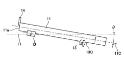
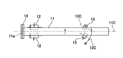
図1及び図2は、本発明の管の回転支持装置の一形態例を示すもので、図1は正面図、図2は平面図である。この管の回転支持装置は、傾斜させた状態の管11の管軸方向上部側を支持する一対の駆動側支持ローラー12,12と、管軸方向上部側を支持する一対の従動側支持ローラー13,13と、管11の傾斜方向上部端面11aに当接する上部支持手段14とで形成されている。
1 and 2 show one embodiment of the tube rotation support device of the present invention. FIG. 1 is a front view and FIG. 2 is a plan view. The tube rotation support device includes a pair of drive-
前記管11は、支持ローラー12,13で支持可能な直管で、ある程度の剛性を有しているものならば材質は特に限定されず、鋼管、ステンレス管、アルミ管等の金属管や、塩化ビニル管、ポリエチレン管等の樹脂管を使用することができる。水平面Hに対する管11の管軸11Cの傾斜角度θは、管11内に注入する液体の種類や管11の材質に応じて設定すればよいが、通常は、5〜20度の範囲が適当であり、傾斜角度θが小さ過ぎると管11を傾斜させた効果が十分に得られず、傾斜角度θが大き過ぎると管11の支持が困難になる。
The
各ローラー12,13及び上部支持手段14は、図示しないフレーム等に固定された状態となっており、駆動側支持ローラー12には、図示しないモーター等の駆動手段が、直接あるいはギアやチェーンを介して接続されている。また、前記従動側支持ローラー13の回転軸13Cは、管11の管軸11Cに対して非平行な状態に傾斜した状態で設置されている。
The
管軸11Cに対する回転軸13Cの傾斜角度αは、駆動側支持ローラー12の作用で回転している管11によって従動側支持ローラー13が無理なく回転することができ、両者が接触して互いに逆方向に回転したときに、管軸方向に自由に移動可能な管11と、固定された駆動側支持ローラー12との間に、管11を傾斜方向上部側に向けて移動させる方向の力が発生するように設定されている。さらに、管11に接触する駆動側支持ローラー12の円周面の形状、例えば、駆動側支持ローラー12が円柱状、樽型、円盤状等の形状による両者の接触状態の相違、管11の材質と駆動側支持ローラー12の円周面の材質、管11の重量、外径、傾斜角度、回転速度、その他の条件を考慮して回転軸13Cの傾斜角度αが決定される。
The inclination angle α of the rotating
例えば、駆動側支持ローラー12が矢印Aの方向に回転すると、管11は矢印Bの方向に回転し、従動側支持ローラー13は矢印Cの方向に回転する。このとき、従動側支持ローラー13における管11と接触する面の回転方向が管11の傾斜方向上部側に傾斜していれば、管11を傾斜方向上部側に向けて移動させる方向の力が発生する。
For example, when the driving
通常の場合、回転軸13Cは、図1に示すように、管外面を水平方向から見たときには、管軸11Cの傾斜角度θに対して回転軸13Cは同一角度乃至略同一角度とし、図2に示すように、管外面を鉛直方向から見たときの回転軸13Cを、管軸11Cに対して適当な角度傾斜させて非平行な状態とすればよい。
In the normal case, as shown in FIG. 1, when the outer surface of the tube is viewed from the horizontal direction, the
また、従動側支持ローラー13は、管11に対してある程度の摩擦抵抗を有するものであって、管11の回転に追随して滑らずに回転するように形成されている。従動側支持ローラー13の材質は、管11の外面に傷付けることがなく、耐摩耗性が良好で、摩擦抵抗の大きなものが望ましい。具体的には、硬質ポリウレタン樹脂、合成ゴム系樹脂等を挙げることができる。
The driven
一方、駆動側支持ローラー12は、その回転軸が管軸11Cと平行になるように設置されており、材質は、管11との回転接触で管11に傷を付けることがなければ任意の材質を選定できるが、確実な支持性を得るためには管11よりも堅い材質のものが望ましく、例えば、SUS304のようなステンレス鋼や、S45C等の鋼で形成することが好ましい。また、駆動側支持ローラー12の形状は、管11を指示した状態で回転力を伝達できればよく、円柱状、樽型状等に形成することができる。
On the other hand, the drive
上部支持手段14は、管11の傾斜方向上部端面11aに当接することにより、管11の上昇限を規制するためのものであり、回転する端面11aに当接した状態で管11の回転を妨げることなく、また、管端面11aを傷付けることのない材質及び形状に形成されている。材質としては、ステンレス鋼のような金属、塩化ビニル等の硬質合成樹脂を使用することができ、当接面に低摩耗性材料の被覆を施すこともできる。通常、上部支持手段14には板状のものを用いることができるが、必要に応じて管軸11Cに直交する方向の回転軸を有するローラーを用いることもできる。また、上部支持手段14は、管11の傾斜方向上部端面11aの上部側に当接させ、下部側に液体注入手段を設置できるようにしておくことが好ましいが、上部支持手段14と液体注入手段とを一体形成することもできる。
The upper support means 14 is for restricting the ascending limit of the
管11の回転速度は、管11の外径、管11の内面に塗布又は注入する液体の粘度等の性状や、塗布状態等の仕上がりにより適当に設定することができる。通常は、毎分200回転以下の回転速度が適当であり、高速で回転させると従動側支持ローラー13との間に過度な摩擦が発生して管11や従動側支持ローラー13に損傷を与えるおそれがあり、低速で回転させると塗布膜にムラができやすくなる。
The rotational speed of the
管11の内面に液体を注入する手段は、液体の状態に応じて任意に選定することができるが、管11の傾斜方向上部側開口のできるだけ端面に近い位置にノズル等を設置し、回転する管11の内面に直接接触させた状態で液体を管内面に注入することにより、管内面の上端部まで均一に液体を注入することができる。また、管11の上部側開口の位置は、前記上部支持手段14によって一定位置に規制されているので、液体注入手段から注入する液体を管内面の同じ位置に確実に注入することができる。
The means for injecting the liquid into the inner surface of the
また、管11の傾斜角度と液体の注入速度とを適切に設定することにより、上部側開口から液体が流れ落ちることがなくなり、上部支持手段14や管外面に液体が付着することを防止できる。さらに、液体注入後は、管11の一方の開口から熱風等を供給することにより、短時間で乾燥させることができる。
Further, by appropriately setting the inclination angle of the
このように形成した回転支持装置は、所定位置に配置した駆動側支持ローラー12及び従動側支持ローラー13の上に適当に管11を載置して駆動側支持ローラー12を所定の方向に所定の回転速度で回転させると、前述の従動側支持ローラー13の作用で管11が傾斜方向上部側に向けて移動し、管11の傾斜方向上部端面11aが上部支持手段14に当接した状態で支持されて回転することになる。この状態で液体注入手段から接着剤等の液体を管内に注入することにより、管内面に均一に接着剤等を塗布することができる。
The thus formed rotation support device appropriately places the
なお、本形態例では、一対の駆動側支持ローラー12と一対の従動側支持ローラー13とで管11の2箇所を支持するようにしたが、3箇所以上の支持ローラーで管11を支持するようにしてもよく、管11の回転駆動は、支持ローラーとは別の駆動手段、例えばベルト等で行うことも可能である。
In this embodiment, the pair of driving
JIS G 3452に規定された呼び径100の配管用炭素鋼鋼管(外径114.3mm、長さ4000mm)を、水平面からの傾斜角度θが10度で支持されるように駆動側支持ローラー12及び従動側支持ローラー13をそれぞれ設置した。駆動側支持ローラー12は、S45C鋼で最大外径が60mm、長さが60mmの樽型形状に形成した。従動側支持ローラー13は、硬質ポリウレタンで外径が90mm、長さ30mmの円柱状に形成し、管軸11Cに対する回転軸13Cの傾斜角度αは4度に設定した。上部支持手段14には、厚さ1.5mmのステンレス鋼(SUS304)製パンチングプレートを使用した。
A drive-
管11を毎分17回転(周速度毎秒100mm)で回転させると、従動側支持ローラー13の作用で管11が毎分200mmの速度で傾斜方向上部側に向けて移動し、管11の傾斜方向上部端面11aが上部支持手段14に当接した位置で停止し、そのままの状態で回転を継続した。
When the
比較として、管軸11Cに対する回転軸13Cの傾斜角度αを2度に設定したときは、管11は傾斜方向いずれにも移動せず、最初に管11を載置した位置のままで回転を続けた。また、管軸11Cに対する回転軸13Cの傾斜角度αを0度に設定すると、管11は傾斜方向下方に移動してしまった。
As a comparison, when the inclination angle α of the
本発明の管の回転支持装置は、発泡樹脂層を形成した複合管を製造する際に充填接着剤を金属管の内面に塗布する工程や、樹脂ライニング鋼管を製造する際に接着剤を金属管の内面に塗布する工程、金属管や樹脂管の内面を洗浄する工程等に利用することができる。 The pipe rotation support device of the present invention includes a step of applying a filling adhesive to the inner surface of a metal pipe when manufacturing a composite pipe formed with a foamed resin layer, and an adhesive agent when manufacturing a resin-lined steel pipe. It can utilize for the process of apply | coating to the inner surface of this, the process of wash | cleaning the inner surface of a metal tube or a resin tube, etc.
11…管、11a…傾斜方向上部端面、11C…管軸、12…駆動側支持ローラー、13…従動側支持ローラー、13C…回転軸、14…上部支持手段、H…水平面、α…管軸11Cに対する回転軸13Cの傾斜角度、θ…水平面Hに対する管11の管軸11Cの傾斜角度
DESCRIPTION OF
Claims (1)
Priority Applications (1)
| Application Number | Priority Date | Filing Date | Title |
|---|---|---|---|
| JP2004120611A JP2005296895A (en) | 2004-04-15 | 2004-04-15 | Apparatus for rotating and supporting tube |
Applications Claiming Priority (1)
| Application Number | Priority Date | Filing Date | Title |
|---|---|---|---|
| JP2004120611A JP2005296895A (en) | 2004-04-15 | 2004-04-15 | Apparatus for rotating and supporting tube |
Publications (1)
| Publication Number | Publication Date |
|---|---|
| JP2005296895A true JP2005296895A (en) | 2005-10-27 |
Family
ID=35329086
Family Applications (1)
| Application Number | Title | Priority Date | Filing Date |
|---|---|---|---|
| JP2004120611A Pending JP2005296895A (en) | 2004-04-15 | 2004-04-15 | Apparatus for rotating and supporting tube |
Country Status (1)
| Country | Link |
|---|---|
| JP (1) | JP2005296895A (en) |
Cited By (2)
| Publication number | Priority date | Publication date | Assignee | Title |
|---|---|---|---|---|
| CN110180721A (en) * | 2019-06-27 | 2019-08-30 | 北京无线电计量测试研究所 | A kind of supporting tool structure for the japanning of revolving shell inner wall |
| CN113083565A (en) * | 2021-06-08 | 2021-07-09 | 山东奥扬新能源科技股份有限公司 | Clamping tool for bottle processing |
-
2004
- 2004-04-15 JP JP2004120611A patent/JP2005296895A/en active Pending
Cited By (2)
| Publication number | Priority date | Publication date | Assignee | Title |
|---|---|---|---|---|
| CN110180721A (en) * | 2019-06-27 | 2019-08-30 | 北京无线电计量测试研究所 | A kind of supporting tool structure for the japanning of revolving shell inner wall |
| CN113083565A (en) * | 2021-06-08 | 2021-07-09 | 山东奥扬新能源科技股份有限公司 | Clamping tool for bottle processing |
Similar Documents
| Publication | Publication Date | Title |
|---|---|---|
| EP3472857B1 (en) | Device and method for treating substrates using a support roller having a porous material | |
| JP2014024160A (en) | Pipe inner surface polishing device | |
| JP2005296895A (en) | Apparatus for rotating and supporting tube | |
| JP2007130559A (en) | Rotary ultrasonic cleaning apparatus for roll | |
| JP5902927B2 (en) | Coating apparatus and coating method | |
| JP6355507B2 (en) | Elastic roller manufacturing method and coating apparatus | |
| JPH09174742A (en) | Laminate, cleaning blade and manufacture thereof | |
| CN117225626A (en) | Spraying equipment for nonmetallic expansion joint | |
| WO2015145817A1 (en) | Coating device, coating method, and method for producing resin film having coating film | |
| JP4068449B2 (en) | Coating film forming apparatus and coating film forming method | |
| JP2007111658A (en) | Coating roll | |
| JP5268530B2 (en) | Adhesive application apparatus and method | |
| KR102172665B1 (en) | Driving Apparatus For Non Contact Vertical Typed Developing System For Board | |
| JP6989053B1 (en) | Coating device and coating method | |
| CN104275319A (en) | Surface cleaning apparatus | |
| JP2005315594A (en) | Measuring method of coefficient of friction and measuring instrument therefor | |
| JP2004066215A (en) | Coating roller, roller type coating machine, roller type coating machine usable for curved surface, and automatic coating machine | |
| BE617096A (en) | ||
| JP4953867B2 (en) | Painting equipment | |
| JP5062125B2 (en) | Coating method and coating apparatus | |
| JP4599863B2 (en) | Annular coating device, annular coating method | |
| JP4806903B2 (en) | Cylindrical core, coating device, and method for producing polyimide resin endless belt | |
| JPS625665B2 (en) | ||
| JP2006281172A (en) | Coating device and coating method of web, and manufacturing method of coating film-formed web | |
| JP2005111305A (en) | Method and apparatus for coating inner surface of existing piping |