JP2005296894A - Stirring blade - Google Patents
Stirring blade Download PDFInfo
- Publication number
- JP2005296894A JP2005296894A JP2004120610A JP2004120610A JP2005296894A JP 2005296894 A JP2005296894 A JP 2005296894A JP 2004120610 A JP2004120610 A JP 2004120610A JP 2004120610 A JP2004120610 A JP 2004120610A JP 2005296894 A JP2005296894 A JP 2005296894A
- Authority
- JP
- Japan
- Prior art keywords
- stirring blade
- plate
- stirring
- blade
- wing
- Prior art date
- Legal status (The legal status is an assumption and is not a legal conclusion. Google has not performed a legal analysis and makes no representation as to the accuracy of the status listed.)
- Pending
Links
Images
Landscapes
- Mixers Of The Rotary Stirring Type (AREA)
Abstract
Description
本発明は、化学工業や薬品工業や食品工業等における液−液又は固−液の混合を効率的に行うことができる撹拌翼に関する。 The present invention relates to a stirring blade capable of efficiently performing liquid-liquid or solid-liquid mixing in the chemical industry, the pharmaceutical industry, the food industry, and the like.
出願人による略台形状に形成した複数の板状翼体を回転軸に嵌着するハブ部に組込む撹拌翼が知られている(特許文献1参照)。
前記撹拌翼によれば、該撹拌翼の回転に伴い各翼体の回転方向と逆の後退側の背面に負圧が生じこの負圧に取り込まれた流れがその後慣性力によって吐出されるが、撹拌翼の回転動力の割に吐出効率が高くない問題点があった。 According to the stirring blade, a negative pressure is generated on the back side opposite to the rotation direction of each blade body with the rotation of the stirring blade, and the flow taken into the negative pressure is then discharged by the inertial force. There was a problem that the discharge efficiency was not high for the rotational power of the stirring blade.
本発明はこのような問題点を解消し、撹拌翼の回転動力が低く吐出効率が高い、低コストの撹拌翼を提供することを目的とする。 An object of the present invention is to solve such problems and to provide a low-cost stirring blade having low rotational power of the stirring blade and high discharge efficiency.
この目的を達成すべく本発明は複数の板状翼体を、該板状翼体の根部において回転中心から回転方向の前進側へ隔離して配置し、互に連結固定した。 In order to achieve this object, in the present invention, a plurality of plate-like wing bodies are arranged at the root of the plate-like wing body so as to be separated from the rotation center toward the forward side in the rotation direction, and are connected and fixed to each other.
本発明によれば、構造の簡単な板状翼体を用いて高い吐出効率を有する撹拌翼とすることができるので、低コストでしかも高効率の撹拌翼を提供できる効果を有する。 According to the present invention, it is possible to provide a stirring blade having high discharge efficiency using a plate-like blade body having a simple structure, and therefore, it is possible to provide a low-cost and high-efficiency stirring blade.
本発明の撹拌翼の最良の形態の各実施例を以下に示す。 Examples of the best mode of the stirring blade of the present invention are shown below.
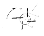
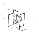
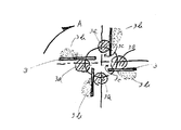
図1は実施例1の撹拌翼1の平面図であり、図2は該撹拌翼1の斜視図である。 FIG. 1 is a plan view of the stirring blade 1 of Example 1, and FIG. 2 is a perspective view of the stirring blade 1.
前記撹拌翼1は、中心部の回転円盤状体2と4枚の板状翼体3とからなり、矢印Aの方向に回転する。
The stirring blade 1 is composed of a rotating disk-
前記板状翼体3は平板状で縦長の長方形に形成され、各板状翼体3の根部を回転中心2aから回転方向の前進側へ間隔Dだけ離して、オフセット状に前記円盤状体2に固定されている。
The plate-
尚、該間隔Dは、前記回転円盤状体2の直径の10分の1乃至2分の1に相当する長さとする。
The distance D is a length corresponding to one-tenth to one-half of the diameter of the rotating disk-
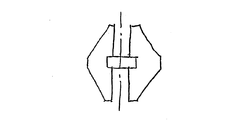
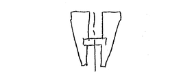
又、前記板状翼体3は長方形以外の、例えば図3に示す如き側方へ凸の梯形状としてもよく、又は図4に示す如く、頂点を上部に配置した三角形状としてもよく、或いは又図5の如く、頂点を下部に配置した逆三角形状としてもよい。
Further, the plate-
尚、図1乃至図5では、回転円盤状体2を前記板状翼体3の上下方向の中間部に固定したが、これは前記回転円盤状体2を前記板状翼体3の下端部、又はその他の部位に固定するようにしてもよい。
In FIG. 1 to FIG. 5, the rotating disk-
次に本実施例の使用方法及びその効果について説明する。 Next, the usage method and effects of the present embodiment will be described.
撹拌翼1を撹拌槽内に垂設して使用するときは、前記回転円盤状体2の中心部2aに回転軸(図示せず)を挿通固定して、該回転軸を図6の矢印Aの方向に回転駆動して撹拌槽内の液体等の撹拌を行なう。
When the stirring blade 1 is used while being suspended in the stirring tank, a rotating shaft (not shown) is inserted and fixed in the central portion 2a of the rotating disk-
撹拌翼1の板状翼体3の先端部付近における撹拌液の流れは、回転中心に対して放射状に板状翼体を配置した従来の撹拌翼とは異なって、前記板状翼体3の前面に対して90度よりも少許少ない角度で衝突する。
The flow of the stirring liquid in the vicinity of the tip of the plate-
これは丁度、後方湾曲翼と同じ効果となり、直線放射翼と較べて後方湾曲翼の方が高効率であることから、間隔Dだけオフセットした本撹拌翼1もその撹拌抵抗が低下して高効率が得られる。 This is exactly the same effect as the backward curved blade, and the backward curved blade is more efficient than the straight radiating blade. Therefore, the stirring blade 1 offset by the distance D also has lower stirring resistance and is highly efficient. Is obtained.
更に又、本撹拌翼1の板状翼体3は、該板状翼体3が回転中心から間隔Dだけオフセットして配置されているため、図6に示すように板状翼体3の背面に発生する負圧3aが増大して、板状翼体3の腹側の正圧3b側から前記負圧3a側へと導かれる流れ3cを生ずる。この流れ3cの発生により撹拌翼1は高い吐出効率を実現することができ、前述した撹拌低下との相乗効果により更に高効率が得られる。
Furthermore, the plate-
尚、本実施例では撹拌翼1に板状翼体3を4枚取付けた例を示したが、これは4枚以外の数であってもよい。
In the present embodiment, an example in which four plate-
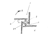
図7は実施例2の撹拌翼5の平面図である。
FIG. 7 is a plan view of the
撹拌翼5を形成する4枚の板状翼体6は、各、その根部において連結杆7を介してボス8に、該ボス8の回転方向(矢印A)の前進側へ間隔Dだけ離して、オフセット状に連結固定している。
The four plate-
前記ボス8の中心部には回転軸が挿通する軸孔8aを有している。
A central hole of the
各板状翼体6は、前記実施例1における板状翼体3と同様の形状を有しており、又、前記間隔Dも前記実施例1の間隔Dと略同様の長さに形成されている。
Each plate-
撹拌翼5の使用方法及びその効果は、前記実施例1と同様である。
The method of using the
尚、本実施例で撹拌翼5は板状翼体6を4枚有する例を示したが、これは4枚以外の数であってもよい。
In the present embodiment, the example in which the
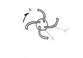
本発明の実施例3の撹拌翼10の平面図を図8に示した。
The top view of the
撹拌翼10は、板状翼体11が撹拌翼10の回転方向(矢印A)とは逆の後退側へ向かって3段に折り曲げて形成されている以外は、前記実施例1の構造と同じである。
The
即ち、該板状翼体11の根部を回転中心2aから回転方向の前進側へ間隔Dだけ離して、オフセット状に回転円盤状体2に固定している。
That is, the root part of the plate-
このように後方湾曲翼とすることにより、撹拌翼10は前記実施例1の撹拌翼1よりも更に高効率な撹拌翼とすることができる。
By using the backward curved blade as described above, the stirring
尚、前記板状翼体11の折り曲げは3段以外の数の折り曲げ数としてもよく、又は図9に示す板状翼体11´の如く、後退側へ湾曲させて形成してもよい。
Note that the plate-
本発明の実施例4を図10乃至図12により説明する。 A fourth embodiment of the present invention will be described with reference to FIGS.
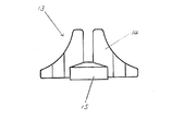
図10は本実施例の撹拌翼13の平面図であり、図11にその側面図(一部省略)を示した。
FIG. 10 is a plan view of the stirring
本撹拌翼13は、4枚の板状翼体14と回転円盤状体15とからなり、各板状翼体14が回転方向(矢印A)とは逆の後退側へ向かって3段に折り曲げて形成され、回転中心に対してオフセット状に配置されている点は、前記実施例3の撹拌翼10(図8)と同様である。
The main
本実施例4の板状翼体14は、頂点を上部に配置した三角形状に形成され、回転円盤状体15の上に固定されている。
The plate-
前記回転円盤状体15は、上部を頭截円錐状に形成すると共に下面を前記板状翼体14よりも少許下方に突出させて、該回転円盤状体15の底部には永久磁石のマグネットカップリングを装着した。
The rotating disk-
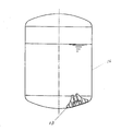
本撹拌翼13は、図12に示す如く、撹拌槽16内の底部に配置し、撹拌槽16の外側に設置した回転磁力発生装置(図示せず)によって該撹拌翼13を回転駆動して、撹拌槽16内の撹拌を行なう。本発明の撹拌翼13は吐出効率が良いので、伝達動力の低いマグネットカップリング方式であっても充分な撹拌を行なうことができる。
As shown in FIG. 12, the
又、前記回転円盤状体14の上面をテーパーを有する頭截円錐状としたので、撹拌液の流動面及び撹拌翼の洗浄性の面が向上して、好結果が得られる。
In addition, since the upper surface of the rotating disk-
尚、本実施例では、撹拌翼13の板状翼体15の数を4枚としたが、これは4枚以外の数であってもよい。
In this embodiment, the number of the plate-
本発明の撹拌翼は、化学工業や食品工業等における液−液、又は固−液の混合の分野で、安価でしかも効率の良い撹拌翼として有望である。 The stirring blade of the present invention is promising as an inexpensive and efficient stirring blade in the field of liquid-liquid or solid-liquid mixing in the chemical industry, food industry and the like.
1、5、10、13 撹拌翼
2、15 回転円盤状体
3、6、11、11´、14 板状翼体
7 連結杆
D 間隔(回転方向の前進側への隔離)
1, 5, 10, 13
Claims (4)
4. The plate-like wing body according to any one of claims 1 to 3, wherein the plate-like wing body is bent or curved toward a retreating side opposite to a rotation direction at an intermediate portion or a tip portion thereof. Stirring blade.
Priority Applications (1)
| Application Number | Priority Date | Filing Date | Title |
|---|---|---|---|
| JP2004120610A JP2005296894A (en) | 2004-04-15 | 2004-04-15 | Stirring blade |
Applications Claiming Priority (1)
| Application Number | Priority Date | Filing Date | Title |
|---|---|---|---|
| JP2004120610A JP2005296894A (en) | 2004-04-15 | 2004-04-15 | Stirring blade |
Publications (1)
| Publication Number | Publication Date |
|---|---|
| JP2005296894A true JP2005296894A (en) | 2005-10-27 |
Family
ID=35329085
Family Applications (1)
| Application Number | Title | Priority Date | Filing Date |
|---|---|---|---|
| JP2004120610A Pending JP2005296894A (en) | 2004-04-15 | 2004-04-15 | Stirring blade |
Country Status (1)
| Country | Link |
|---|---|
| JP (1) | JP2005296894A (en) |
Cited By (9)
| Publication number | Priority date | Publication date | Assignee | Title |
|---|---|---|---|---|
| US20100331488A1 (en) * | 2009-06-29 | 2010-12-30 | Konica Minolta Business Technologies, Inc. | Tubular flow reactor and method for producing resin particle using the same |
| JP2011245415A (en) * | 2010-05-26 | 2011-12-08 | Freund Corp | Stirring blade and stirring granulator |
| JP2015073963A (en) * | 2013-10-10 | 2015-04-20 | 株式会社カジワラ | Agitation device |
| US9134635B1 (en) | 2014-04-14 | 2015-09-15 | Xerox Corporation | Method for continuous aggregation of pre-toner particles |
| JP6263658B1 (en) * | 2017-03-24 | 2018-01-17 | 佐竹化学機械工業株式会社 | Stirrer |
| CN108246143A (en) * | 2018-02-06 | 2018-07-06 | 中国科学院过程工程研究所 | A kind of percolation agitating paddle |
| WO2018131339A1 (en) * | 2017-01-11 | 2018-07-19 | 三広アステック株式会社 | Parallel stirring blade |
| JP2018161643A (en) * | 2017-12-18 | 2018-10-18 | 佐竹化学機械工業株式会社 | Stirring device for vaporization and condensation |
| CN114797529A (en) * | 2022-05-24 | 2022-07-29 | 重庆大学 | Elastic folding stirring paddle for strengthening acid hydrolysis of phosphate ore |
Citations (10)
| Publication number | Priority date | Publication date | Assignee | Title |
|---|---|---|---|---|
| JPS5912737A (en) * | 1982-07-13 | 1984-01-23 | Yoshihiro Sakata | Stirring assisting apparatus in recirculation tank |
| JPS6138621A (en) * | 1984-07-31 | 1986-02-24 | Toko Sangyo Kk | Dissolver |
| JPH02133425U (en) * | 1989-04-10 | 1990-11-06 | ||
| JPH05107668A (en) * | 1991-10-14 | 1993-04-30 | Mitsubishi Paper Mills Ltd | Apparatus for producing silver halide photographic emulsion |
| JPH06304463A (en) * | 1993-04-21 | 1994-11-01 | Yamakawa Sangyo Kk | Agitator for granulating apparatus |
| JPH1099671A (en) * | 1996-10-01 | 1998-04-21 | Nara Kikai Seisakusho:Kk | Agitation type mixing granulator |
| JPH10510583A (en) * | 1995-09-27 | 1998-10-13 | レンツィング アクチェンゲゼルシャフト | Thin film processing equipment |
| JPH11276871A (en) * | 1998-03-31 | 1999-10-12 | Sumitomo Heavy Ind Ltd | Vertical agitating apparatus |
| JP2001353434A (en) * | 2000-04-13 | 2001-12-25 | Toli Corp | Stirring implement |
| JP2002273188A (en) * | 2001-03-19 | 2002-09-24 | Aoki Kk | Stirrer |
-
2004
- 2004-04-15 JP JP2004120610A patent/JP2005296894A/en active Pending
Patent Citations (10)
| Publication number | Priority date | Publication date | Assignee | Title |
|---|---|---|---|---|
| JPS5912737A (en) * | 1982-07-13 | 1984-01-23 | Yoshihiro Sakata | Stirring assisting apparatus in recirculation tank |
| JPS6138621A (en) * | 1984-07-31 | 1986-02-24 | Toko Sangyo Kk | Dissolver |
| JPH02133425U (en) * | 1989-04-10 | 1990-11-06 | ||
| JPH05107668A (en) * | 1991-10-14 | 1993-04-30 | Mitsubishi Paper Mills Ltd | Apparatus for producing silver halide photographic emulsion |
| JPH06304463A (en) * | 1993-04-21 | 1994-11-01 | Yamakawa Sangyo Kk | Agitator for granulating apparatus |
| JPH10510583A (en) * | 1995-09-27 | 1998-10-13 | レンツィング アクチェンゲゼルシャフト | Thin film processing equipment |
| JPH1099671A (en) * | 1996-10-01 | 1998-04-21 | Nara Kikai Seisakusho:Kk | Agitation type mixing granulator |
| JPH11276871A (en) * | 1998-03-31 | 1999-10-12 | Sumitomo Heavy Ind Ltd | Vertical agitating apparatus |
| JP2001353434A (en) * | 2000-04-13 | 2001-12-25 | Toli Corp | Stirring implement |
| JP2002273188A (en) * | 2001-03-19 | 2002-09-24 | Aoki Kk | Stirrer |
Cited By (16)
| Publication number | Priority date | Publication date | Assignee | Title |
|---|---|---|---|---|
| US20100331488A1 (en) * | 2009-06-29 | 2010-12-30 | Konica Minolta Business Technologies, Inc. | Tubular flow reactor and method for producing resin particle using the same |
| CN101934213A (en) * | 2009-06-29 | 2011-01-05 | 柯尼卡美能达商用科技株式会社 | The cast flow reactor, used the manufacture method of the resin particle of this cast flow reactor |
| US8293181B2 (en) * | 2009-06-29 | 2012-10-23 | Konica Minolta Business Technologies, Inc. | Tubular flow reactor and method for producing resin particle using the same |
| JP2011245415A (en) * | 2010-05-26 | 2011-12-08 | Freund Corp | Stirring blade and stirring granulator |
| JP2015073963A (en) * | 2013-10-10 | 2015-04-20 | 株式会社カジワラ | Agitation device |
| US9134635B1 (en) | 2014-04-14 | 2015-09-15 | Xerox Corporation | Method for continuous aggregation of pre-toner particles |
| WO2018131339A1 (en) * | 2017-01-11 | 2018-07-19 | 三広アステック株式会社 | Parallel stirring blade |
| KR20190067231A (en) * | 2017-01-11 | 2019-06-14 | 산코아스텍 가부시키가이샤 | Parallel stirring wing |
| KR102360366B1 (en) * | 2017-01-11 | 2022-02-10 | 산코아스텍 가부시키가이샤 | parallel stirring blades |
| US11484851B2 (en) | 2017-01-11 | 2022-11-01 | Sanko Astec Inc. | Parallel stirring blade |
| JP6263658B1 (en) * | 2017-03-24 | 2018-01-17 | 佐竹化学機械工業株式会社 | Stirrer |
| JP2018161614A (en) * | 2017-03-24 | 2018-10-18 | 佐竹化学機械工業株式会社 | Stirring device |
| JP2018161643A (en) * | 2017-12-18 | 2018-10-18 | 佐竹化学機械工業株式会社 | Stirring device for vaporization and condensation |
| CN108246143A (en) * | 2018-02-06 | 2018-07-06 | 中国科学院过程工程研究所 | A kind of percolation agitating paddle |
| CN108246143B (en) * | 2018-02-06 | 2020-12-25 | 中国科学院过程工程研究所 | Cross-flow stirring paddle |
| CN114797529A (en) * | 2022-05-24 | 2022-07-29 | 重庆大学 | Elastic folding stirring paddle for strengthening acid hydrolysis of phosphate ore |
Similar Documents
| Publication | Publication Date | Title |
|---|---|---|
| US5791780A (en) | Impeller assembly with asymmetric concave blades | |
| CN103958041B (en) | There is the agitator arm of blade paddle shape | |
| JP2005296894A (en) | Stirring blade | |
| BR112015031637B1 (en) | MIXING ASSEMBLIES INCLUDING MAGNETIC IMPELLERS | |
| TWM495896U (en) | Agitator | |
| EP1582253A3 (en) | An agitator, a circulatory cleaning device attached to the agitator, and a circulatory line system comprising the circulatory cleaning device | |
| AU720728B2 (en) | Mixer sparging apparatus | |
| JP6393694B2 (en) | Stirring blade and stirring device | |
| JP2006177125A (en) | Steel pipe pile | |
| US9108170B2 (en) | Mixing impeller having channel-shaped vanes | |
| JP3598736B2 (en) | Stirrer | |
| US20090141586A1 (en) | Mixing apparatus | |
| CA2506286A1 (en) | An agitator, a circulatory cleaning device attached to the agitator, and a circulatory line system comprising the circulatory cleaning device | |
| JP2001321651A (en) | Agitating device | |
| JP5758345B2 (en) | Impeller | |
| JP2014233676A (en) | Agitation blade | |
| JP6074647B2 (en) | Stirring method and stirrer | |
| JP2006043668A (en) | Fluid stirring device, turbine-type stirrer and baffle used therefor | |
| WO2018119842A1 (en) | Bladeless stirrer | |
| JP2005146649A (en) | Tip part structure of pile body | |
| EP2153885A1 (en) | A foaming device for foaming a liquid substance | |
| CN204352596U (en) | For the electromagnetic agitation separator of bio-pharmaceuticals | |
| CN217013594U (en) | Stirring assembly of cold extraction coffee machine | |
| JP4040373B2 (en) | Mechanism to prevent generation of water surface swirl in agitator | |
| KR200428560Y1 (en) | A blade member for bubble of mixer |
Legal Events
| Date | Code | Title | Description |
|---|---|---|---|
| A621 | Written request for application examination |
Free format text: JAPANESE INTERMEDIATE CODE: A621 Effective date: 20070410 |
|
| A977 | Report on retrieval |
Free format text: JAPANESE INTERMEDIATE CODE: A971007 Effective date: 20090514 |
|
| A131 | Notification of reasons for refusal |
Free format text: JAPANESE INTERMEDIATE CODE: A131 Effective date: 20090520 |
|
| A521 | Written amendment |
Free format text: JAPANESE INTERMEDIATE CODE: A523 Effective date: 20090629 |
|
| A131 | Notification of reasons for refusal |
Free format text: JAPANESE INTERMEDIATE CODE: A131 Effective date: 20091030 |
|
| A131 | Notification of reasons for refusal |
Free format text: JAPANESE INTERMEDIATE CODE: A131 Effective date: 20100329 |
|
| A02 | Decision of refusal |
Free format text: JAPANESE INTERMEDIATE CODE: A02 Effective date: 20100729 |
