JP2005296883A - Droplet production apparatus - Google Patents
Droplet production apparatus Download PDFInfo
- Publication number
- JP2005296883A JP2005296883A JP2004119831A JP2004119831A JP2005296883A JP 2005296883 A JP2005296883 A JP 2005296883A JP 2004119831 A JP2004119831 A JP 2004119831A JP 2004119831 A JP2004119831 A JP 2004119831A JP 2005296883 A JP2005296883 A JP 2005296883A
- Authority
- JP
- Japan
- Prior art keywords
- orifice
- droplets
- droplet
- orifice holes
- holes
- Prior art date
- Legal status (The legal status is an assumption and is not a legal conclusion. Google has not performed a legal analysis and makes no representation as to the accuracy of the status listed.)
- Pending
Links
- 238000004519 manufacturing process Methods 0.000 title claims abstract description 14
- 239000002002 slurry Substances 0.000 claims abstract description 21
- 229920000642 polymer Polymers 0.000 claims description 15
- 239000000178 monomer Substances 0.000 claims description 13
- 239000011324 bead Substances 0.000 claims description 11
- 239000007788 liquid Substances 0.000 abstract description 13
- 239000006185 dispersion Substances 0.000 abstract description 3
- 230000006866 deterioration Effects 0.000 abstract description 2
- PPBRXRYQALVLMV-UHFFFAOYSA-N Styrene Chemical compound C=CC1=CC=CC=C1 PPBRXRYQALVLMV-UHFFFAOYSA-N 0.000 description 33
- 239000002245 particle Substances 0.000 description 15
- 238000000034 method Methods 0.000 description 13
- 238000006116 polymerization reaction Methods 0.000 description 7
- 239000004372 Polyvinyl alcohol Substances 0.000 description 5
- 230000000379 polymerizing effect Effects 0.000 description 5
- 229920002451 polyvinyl alcohol Polymers 0.000 description 5
- 239000002270 dispersing agent Substances 0.000 description 4
- -1 pn-butylstyrene Chemical compound 0.000 description 4
- 239000003505 polymerization initiator Substances 0.000 description 4
- 238000010557 suspension polymerization reaction Methods 0.000 description 4
- UHOVQNZJYSORNB-UHFFFAOYSA-N Benzene Chemical compound C1=CC=CC=C1 UHOVQNZJYSORNB-UHFFFAOYSA-N 0.000 description 3
- XEKOWRVHYACXOJ-UHFFFAOYSA-N Ethyl acetate Chemical compound CCOC(C)=O XEKOWRVHYACXOJ-UHFFFAOYSA-N 0.000 description 3
- MHAJPDPJQMAIIY-UHFFFAOYSA-N Hydrogen peroxide Chemical compound OO MHAJPDPJQMAIIY-UHFFFAOYSA-N 0.000 description 3
- 239000002202 Polyethylene glycol Substances 0.000 description 3
- YXFVVABEGXRONW-UHFFFAOYSA-N Toluene Chemical compound CC1=CC=CC=C1 YXFVVABEGXRONW-UHFFFAOYSA-N 0.000 description 3
- 239000002253 acid Substances 0.000 description 3
- 239000007864 aqueous solution Substances 0.000 description 3
- 239000010419 fine particle Substances 0.000 description 3
- 239000000203 mixture Substances 0.000 description 3
- VLKZOEOYAKHREP-UHFFFAOYSA-N n-Hexane Chemical compound CCCCCC VLKZOEOYAKHREP-UHFFFAOYSA-N 0.000 description 3
- 229920001223 polyethylene glycol Polymers 0.000 description 3
- 239000007787 solid Substances 0.000 description 3
- 238000003756 stirring Methods 0.000 description 3
- MYRTYDVEIRVNKP-UHFFFAOYSA-N 1,2-Divinylbenzene Chemical compound C=CC1=CC=CC=C1C=C MYRTYDVEIRVNKP-UHFFFAOYSA-N 0.000 description 2
- UAJRSHJHFRVGMG-UHFFFAOYSA-N 1-ethenyl-4-methoxybenzene Chemical compound COC1=CC=C(C=C)C=C1 UAJRSHJHFRVGMG-UHFFFAOYSA-N 0.000 description 2
- OZAIFHULBGXAKX-UHFFFAOYSA-N 2-(2-cyanopropan-2-yldiazenyl)-2-methylpropanenitrile Chemical compound N#CC(C)(C)N=NC(C)(C)C#N OZAIFHULBGXAKX-UHFFFAOYSA-N 0.000 description 2
- SMZOUWXMTYCWNB-UHFFFAOYSA-N 2-(2-methoxy-5-methylphenyl)ethanamine Chemical compound COC1=CC=C(C)C=C1CCN SMZOUWXMTYCWNB-UHFFFAOYSA-N 0.000 description 2
- NIXOWILDQLNWCW-UHFFFAOYSA-N 2-Propenoic acid Natural products OC(=O)C=C NIXOWILDQLNWCW-UHFFFAOYSA-N 0.000 description 2
- XFCMNSHQOZQILR-UHFFFAOYSA-N 2-[2-(2-methylprop-2-enoyloxy)ethoxy]ethyl 2-methylprop-2-enoate Chemical compound CC(=C)C(=O)OCCOCCOC(=O)C(C)=C XFCMNSHQOZQILR-UHFFFAOYSA-N 0.000 description 2
- CSCPPACGZOOCGX-UHFFFAOYSA-N Acetone Chemical compound CC(C)=O CSCPPACGZOOCGX-UHFFFAOYSA-N 0.000 description 2
- HRPVXLWXLXDGHG-UHFFFAOYSA-N Acrylamide Chemical compound NC(=O)C=C HRPVXLWXLXDGHG-UHFFFAOYSA-N 0.000 description 2
- SOGAXMICEFXMKE-UHFFFAOYSA-N Butylmethacrylate Chemical compound CCCCOC(=O)C(C)=C SOGAXMICEFXMKE-UHFFFAOYSA-N 0.000 description 2
- XDTMQSROBMDMFD-UHFFFAOYSA-N Cyclohexane Chemical compound C1CCCCC1 XDTMQSROBMDMFD-UHFFFAOYSA-N 0.000 description 2
- WOBHKFSMXKNTIM-UHFFFAOYSA-N Hydroxyethyl methacrylate Chemical compound CC(=C)C(=O)OCCO WOBHKFSMXKNTIM-UHFFFAOYSA-N 0.000 description 2
- CERQOIWHTDAKMF-UHFFFAOYSA-N Methacrylic acid Chemical compound CC(=C)C(O)=O CERQOIWHTDAKMF-UHFFFAOYSA-N 0.000 description 2
- BAPJBEWLBFYGME-UHFFFAOYSA-N Methyl acrylate Chemical compound COC(=O)C=C BAPJBEWLBFYGME-UHFFFAOYSA-N 0.000 description 2
- IMNFDUFMRHMDMM-UHFFFAOYSA-N N-Heptane Chemical compound CCCCCCC IMNFDUFMRHMDMM-UHFFFAOYSA-N 0.000 description 2
- CDBYLPFSWZWCQE-UHFFFAOYSA-L Sodium Carbonate Chemical compound [Na+].[Na+].[O-]C([O-])=O CDBYLPFSWZWCQE-UHFFFAOYSA-L 0.000 description 2
- 238000009825 accumulation Methods 0.000 description 2
- 230000000052 comparative effect Effects 0.000 description 2
- GMSCBRSQMRDRCD-UHFFFAOYSA-N dodecyl 2-methylprop-2-enoate Chemical compound CCCCCCCCCCCCOC(=O)C(C)=C GMSCBRSQMRDRCD-UHFFFAOYSA-N 0.000 description 2
- FJKIXWOMBXYWOQ-UHFFFAOYSA-N ethenoxyethane Chemical compound CCOC=C FJKIXWOMBXYWOQ-UHFFFAOYSA-N 0.000 description 2
- STVZJERGLQHEKB-UHFFFAOYSA-N ethylene glycol dimethacrylate Substances CC(=C)C(=O)OCCOC(=O)C(C)=C STVZJERGLQHEKB-UHFFFAOYSA-N 0.000 description 2
- FQPSGWSUVKBHSU-UHFFFAOYSA-N methacrylamide Chemical compound CC(=C)C(N)=O FQPSGWSUVKBHSU-UHFFFAOYSA-N 0.000 description 2
- 150000003839 salts Chemical class 0.000 description 2
- XLYOFNOQVPJJNP-UHFFFAOYSA-N water Substances O XLYOFNOQVPJJNP-UHFFFAOYSA-N 0.000 description 2
- QEQBMZQFDDDTPN-UHFFFAOYSA-N (2-methylpropan-2-yl)oxy benzenecarboperoxoate Chemical compound CC(C)(C)OOOC(=O)C1=CC=CC=C1 QEQBMZQFDDDTPN-UHFFFAOYSA-N 0.000 description 1
- UUGXDEDGRPYWHG-UHFFFAOYSA-N (dimethylamino)methyl 2-methylprop-2-enoate Chemical compound CN(C)COC(=O)C(C)=C UUGXDEDGRPYWHG-UHFFFAOYSA-N 0.000 description 1
- WVAFEFUPWRPQSY-UHFFFAOYSA-N 1,2,3-tris(ethenyl)benzene Chemical compound C=CC1=CC=CC(C=C)=C1C=C WVAFEFUPWRPQSY-UHFFFAOYSA-N 0.000 description 1
- ZJQIXGGEADDPQB-UHFFFAOYSA-N 1,2-bis(ethenyl)-3,4-dimethylbenzene Chemical group CC1=CC=C(C=C)C(C=C)=C1C ZJQIXGGEADDPQB-UHFFFAOYSA-N 0.000 description 1
- BJQFWAQRPATHTR-UHFFFAOYSA-N 1,2-dichloro-4-ethenylbenzene Chemical compound ClC1=CC=C(C=C)C=C1Cl BJQFWAQRPATHTR-UHFFFAOYSA-N 0.000 description 1
- VDYWHVQKENANGY-UHFFFAOYSA-N 1,3-Butyleneglycol dimethacrylate Chemical compound CC(=C)C(=O)OC(C)CCOC(=O)C(C)=C VDYWHVQKENANGY-UHFFFAOYSA-N 0.000 description 1
- MWZJGRDWJVHRDV-UHFFFAOYSA-N 1,4-bis(ethenoxy)butane Chemical compound C=COCCCCOC=C MWZJGRDWJVHRDV-UHFFFAOYSA-N 0.000 description 1
- MPPPKRYCTPRNTB-UHFFFAOYSA-N 1-bromobutane Chemical compound CCCCBr MPPPKRYCTPRNTB-UHFFFAOYSA-N 0.000 description 1
- KTZVZZJJVJQZHV-UHFFFAOYSA-N 1-chloro-4-ethenylbenzene Chemical compound ClC1=CC=C(C=C)C=C1 KTZVZZJJVJQZHV-UHFFFAOYSA-N 0.000 description 1
- SAMJGBVVQUEMGC-UHFFFAOYSA-N 1-ethenoxy-2-(2-ethenoxyethoxy)ethane Chemical compound C=COCCOCCOC=C SAMJGBVVQUEMGC-UHFFFAOYSA-N 0.000 description 1
- OZCMOJQQLBXBKI-UHFFFAOYSA-N 1-ethenoxy-2-methylpropane Chemical compound CC(C)COC=C OZCMOJQQLBXBKI-UHFFFAOYSA-N 0.000 description 1
- OEVVKKAVYQFQNV-UHFFFAOYSA-N 1-ethenyl-2,4-dimethylbenzene Chemical compound CC1=CC=C(C=C)C(C)=C1 OEVVKKAVYQFQNV-UHFFFAOYSA-N 0.000 description 1
- NVZWEEGUWXZOKI-UHFFFAOYSA-N 1-ethenyl-2-methylbenzene Chemical compound CC1=CC=CC=C1C=C NVZWEEGUWXZOKI-UHFFFAOYSA-N 0.000 description 1
- JZHGRUMIRATHIU-UHFFFAOYSA-N 1-ethenyl-3-methylbenzene Chemical compound CC1=CC=CC(C=C)=C1 JZHGRUMIRATHIU-UHFFFAOYSA-N 0.000 description 1
- CTXUTPWZJZHRJC-UHFFFAOYSA-N 1-ethenylpyrrole Chemical compound C=CN1C=CC=C1 CTXUTPWZJZHRJC-UHFFFAOYSA-N 0.000 description 1
- QEDJMOONZLUIMC-UHFFFAOYSA-N 1-tert-butyl-4-ethenylbenzene Chemical compound CC(C)(C)C1=CC=C(C=C)C=C1 QEDJMOONZLUIMC-UHFFFAOYSA-N 0.000 description 1
- IGGDKDTUCAWDAN-UHFFFAOYSA-N 1-vinylnaphthalene Chemical class C1=CC=C2C(C=C)=CC=CC2=C1 IGGDKDTUCAWDAN-UHFFFAOYSA-N 0.000 description 1
- BJELTSYBAHKXRW-UHFFFAOYSA-N 2,4,6-triallyloxy-1,3,5-triazine Chemical compound C=CCOC1=NC(OCC=C)=NC(OCC=C)=N1 BJELTSYBAHKXRW-UHFFFAOYSA-N 0.000 description 1
- STMDPCBYJCIZOD-UHFFFAOYSA-N 2-(2,4-dinitroanilino)-4-methylpentanoic acid Chemical compound CC(C)CC(C(O)=O)NC1=CC=C([N+]([O-])=O)C=C1[N+]([O-])=O STMDPCBYJCIZOD-UHFFFAOYSA-N 0.000 description 1
- OEPOKWHJYJXUGD-UHFFFAOYSA-N 2-(3-phenylmethoxyphenyl)-1,3-thiazole-4-carbaldehyde Chemical compound O=CC1=CSC(C=2C=C(OCC=3C=CC=CC=3)C=CC=2)=N1 OEPOKWHJYJXUGD-UHFFFAOYSA-N 0.000 description 1
- JKNCOURZONDCGV-UHFFFAOYSA-N 2-(dimethylamino)ethyl 2-methylprop-2-enoate Chemical compound CN(C)CCOC(=O)C(C)=C JKNCOURZONDCGV-UHFFFAOYSA-N 0.000 description 1
- GOXQRTZXKQZDDN-UHFFFAOYSA-N 2-Ethylhexyl acrylate Chemical compound CCCCC(CC)COC(=O)C=C GOXQRTZXKQZDDN-UHFFFAOYSA-N 0.000 description 1
- WHBAYNMEIXUTJV-UHFFFAOYSA-N 2-chloroethyl prop-2-enoate Chemical compound ClCCOC(=O)C=C WHBAYNMEIXUTJV-UHFFFAOYSA-N 0.000 description 1
- WBIQQQGBSDOWNP-UHFFFAOYSA-N 2-dodecylbenzenesulfonic acid Chemical compound CCCCCCCCCCCCC1=CC=CC=C1S(O)(=O)=O WBIQQQGBSDOWNP-UHFFFAOYSA-N 0.000 description 1
- WDQMWEYDKDCEHT-UHFFFAOYSA-N 2-ethylhexyl 2-methylprop-2-enoate Chemical compound CCCCC(CC)COC(=O)C(C)=C WDQMWEYDKDCEHT-UHFFFAOYSA-N 0.000 description 1
- OMIGHNLMNHATMP-UHFFFAOYSA-N 2-hydroxyethyl prop-2-enoate Chemical compound OCCOC(=O)C=C OMIGHNLMNHATMP-UHFFFAOYSA-N 0.000 description 1
- HFCUBKYHMMPGBY-UHFFFAOYSA-N 2-methoxyethyl prop-2-enoate Chemical compound COCCOC(=O)C=C HFCUBKYHMMPGBY-UHFFFAOYSA-N 0.000 description 1
- XVTXLKJBAYGTJS-UHFFFAOYSA-N 2-methylpenta-1,4-dien-3-one Chemical compound CC(=C)C(=O)C=C XVTXLKJBAYGTJS-UHFFFAOYSA-N 0.000 description 1
- CFVWNXQPGQOHRJ-UHFFFAOYSA-N 2-methylpropyl prop-2-enoate Chemical compound CC(C)COC(=O)C=C CFVWNXQPGQOHRJ-UHFFFAOYSA-N 0.000 description 1
- JLBJTVDPSNHSKJ-UHFFFAOYSA-N 4-Methylstyrene Chemical compound CC1=CC=C(C=C)C=C1 JLBJTVDPSNHSKJ-UHFFFAOYSA-N 0.000 description 1
- DBCAQXHNJOFNGC-UHFFFAOYSA-N 4-bromo-1,1,1-trifluorobutane Chemical compound FC(F)(F)CCCBr DBCAQXHNJOFNGC-UHFFFAOYSA-N 0.000 description 1
- SBVKVAIECGDBTC-UHFFFAOYSA-N 4-hydroxy-2-methylidenebutanamide Chemical compound NC(=O)C(=C)CCO SBVKVAIECGDBTC-UHFFFAOYSA-N 0.000 description 1
- JTHZUSWLNCPZLX-UHFFFAOYSA-N 6-fluoro-3-methyl-2h-indazole Chemical compound FC1=CC=C2C(C)=NNC2=C1 JTHZUSWLNCPZLX-UHFFFAOYSA-N 0.000 description 1
- NIXOWILDQLNWCW-UHFFFAOYSA-M Acrylate Chemical compound [O-]C(=O)C=C NIXOWILDQLNWCW-UHFFFAOYSA-M 0.000 description 1
- NLHHRLWOUZZQLW-UHFFFAOYSA-N Acrylonitrile Chemical compound C=CC#N NLHHRLWOUZZQLW-UHFFFAOYSA-N 0.000 description 1
- 239000004342 Benzoyl peroxide Substances 0.000 description 1
- OMPJBNCRMGITSC-UHFFFAOYSA-N Benzoylperoxide Chemical compound C=1C=CC=CC=1C(=O)OOC(=O)C1=CC=CC=C1 OMPJBNCRMGITSC-UHFFFAOYSA-N 0.000 description 1
- LSNNMFCWUKXFEE-UHFFFAOYSA-M Bisulfite Chemical compound OS([O-])=O LSNNMFCWUKXFEE-UHFFFAOYSA-M 0.000 description 1
- DKPFZGUDAPQIHT-UHFFFAOYSA-N Butyl acetate Natural products CCCCOC(C)=O DKPFZGUDAPQIHT-UHFFFAOYSA-N 0.000 description 1
- RGWYKIVTLWGQHS-UHFFFAOYSA-N CC(C)CCC(C)(C)OC(=O)OO Chemical compound CC(C)CCC(C)(C)OC(=O)OO RGWYKIVTLWGQHS-UHFFFAOYSA-N 0.000 description 1
- 229920002134 Carboxymethyl cellulose Polymers 0.000 description 1
- JIGUQPWFLRLWPJ-UHFFFAOYSA-N Ethyl acrylate Chemical compound CCOC(=O)C=C JIGUQPWFLRLWPJ-UHFFFAOYSA-N 0.000 description 1
- YCKRFDGAMUMZLT-UHFFFAOYSA-N Fluorine atom Chemical compound [F] YCKRFDGAMUMZLT-UHFFFAOYSA-N 0.000 description 1
- 108010010803 Gelatin Proteins 0.000 description 1
- 239000004354 Hydroxyethyl cellulose Substances 0.000 description 1
- VQTUBCCKSQIDNK-UHFFFAOYSA-N Isobutene Chemical group CC(C)=C VQTUBCCKSQIDNK-UHFFFAOYSA-N 0.000 description 1
- YIVJZNGAASQVEM-UHFFFAOYSA-N Lauroyl peroxide Chemical compound CCCCCCCCCCCC(=O)OOC(=O)CCCCCCCCCCC YIVJZNGAASQVEM-UHFFFAOYSA-N 0.000 description 1
- VVQNEPGJFQJSBK-UHFFFAOYSA-N Methyl methacrylate Chemical compound COC(=O)C(C)=C VVQNEPGJFQJSBK-UHFFFAOYSA-N 0.000 description 1
- GYCMBHHDWRMZGG-UHFFFAOYSA-N Methylacrylonitrile Chemical compound CC(=C)C#N GYCMBHHDWRMZGG-UHFFFAOYSA-N 0.000 description 1
- CNCOEDDPFOAUMB-UHFFFAOYSA-N N-Methylolacrylamide Chemical compound OCNC(=O)C=C CNCOEDDPFOAUMB-UHFFFAOYSA-N 0.000 description 1
- WHNWPMSKXPGLAX-UHFFFAOYSA-N N-Vinyl-2-pyrrolidone Chemical compound C=CN1CCCC1=O WHNWPMSKXPGLAX-UHFFFAOYSA-N 0.000 description 1
- CTQNGGLPUBDAKN-UHFFFAOYSA-N O-Xylene Chemical compound CC1=CC=CC=C1C CTQNGGLPUBDAKN-UHFFFAOYSA-N 0.000 description 1
- 229920002472 Starch Polymers 0.000 description 1
- OKKRPWIIYQTPQF-UHFFFAOYSA-N Trimethylolpropane trimethacrylate Chemical compound CC(=C)C(=O)OCC(CC)(COC(=O)C(C)=C)COC(=O)C(C)=C OKKRPWIIYQTPQF-UHFFFAOYSA-N 0.000 description 1
- XTXRWKRVRITETP-UHFFFAOYSA-N Vinyl acetate Chemical compound CC(=O)OC=C XTXRWKRVRITETP-UHFFFAOYSA-N 0.000 description 1
- BZHJMEDXRYGGRV-UHFFFAOYSA-N Vinyl chloride Chemical compound ClC=C BZHJMEDXRYGGRV-UHFFFAOYSA-N 0.000 description 1
- QYKIQEUNHZKYBP-UHFFFAOYSA-N Vinyl ether Chemical class C=COC=C QYKIQEUNHZKYBP-UHFFFAOYSA-N 0.000 description 1
- HVVWZTWDBSEWIH-UHFFFAOYSA-N [2-(hydroxymethyl)-3-prop-2-enoyloxy-2-(prop-2-enoyloxymethyl)propyl] prop-2-enoate Chemical compound C=CC(=O)OCC(CO)(COC(=O)C=C)COC(=O)C=C HVVWZTWDBSEWIH-UHFFFAOYSA-N 0.000 description 1
- UKMBKKFLJMFCSA-UHFFFAOYSA-N [3-hydroxy-2-(2-methylprop-2-enoyloxy)propyl] 2-methylprop-2-enoate Chemical compound CC(=C)C(=O)OCC(CO)OC(=O)C(C)=C UKMBKKFLJMFCSA-UHFFFAOYSA-N 0.000 description 1
- 150000001298 alcohols Chemical class 0.000 description 1
- 239000003945 anionic surfactant Substances 0.000 description 1
- 150000001491 aromatic compounds Chemical class 0.000 description 1
- 235000019400 benzoyl peroxide Nutrition 0.000 description 1
- MPMBRWOOISTHJV-UHFFFAOYSA-N but-1-enylbenzene Chemical compound CCC=CC1=CC=CC=C1 MPMBRWOOISTHJV-UHFFFAOYSA-N 0.000 description 1
- CQEYYJKEWSMYFG-UHFFFAOYSA-N butyl acrylate Chemical compound CCCCOC(=O)C=C CQEYYJKEWSMYFG-UHFFFAOYSA-N 0.000 description 1
- UPIWXMRIPODGLE-UHFFFAOYSA-N butyl benzenecarboperoxoate Chemical compound CCCCOOC(=O)C1=CC=CC=C1 UPIWXMRIPODGLE-UHFFFAOYSA-N 0.000 description 1
- 239000001506 calcium phosphate Substances 0.000 description 1
- 229910000389 calcium phosphate Inorganic materials 0.000 description 1
- 235000011010 calcium phosphates Nutrition 0.000 description 1
- 239000001768 carboxy methyl cellulose Substances 0.000 description 1
- 235000010948 carboxy methyl cellulose Nutrition 0.000 description 1
- 150000001735 carboxylic acids Chemical class 0.000 description 1
- 229920003090 carboxymethyl hydroxyethyl cellulose Polymers 0.000 description 1
- 239000008112 carboxymethyl-cellulose Substances 0.000 description 1
- 229920003086 cellulose ether Polymers 0.000 description 1
- 238000004581 coalescence Methods 0.000 description 1
- 229920006037 cross link polymer Polymers 0.000 description 1
- 230000003247 decreasing effect Effects 0.000 description 1
- XZTWHWHGBBCSMX-UHFFFAOYSA-J dimagnesium;phosphonato phosphate Chemical compound [Mg+2].[Mg+2].[O-]P([O-])(=O)OP([O-])([O-])=O XZTWHWHGBBCSMX-UHFFFAOYSA-J 0.000 description 1
- 229940060296 dodecylbenzenesulfonic acid Drugs 0.000 description 1
- 230000007613 environmental effect Effects 0.000 description 1
- 150000002148 esters Chemical class 0.000 description 1
- UIWXSTHGICQLQT-UHFFFAOYSA-N ethenyl propanoate Chemical compound CCC(=O)OC=C UIWXSTHGICQLQT-UHFFFAOYSA-N 0.000 description 1
- SUPCQIBBMFXVTL-UHFFFAOYSA-N ethyl 2-methylprop-2-enoate Chemical compound CCOC(=O)C(C)=C SUPCQIBBMFXVTL-UHFFFAOYSA-N 0.000 description 1
- 229910052731 fluorine Inorganic materials 0.000 description 1
- 239000011737 fluorine Substances 0.000 description 1
- 229920000159 gelatin Polymers 0.000 description 1
- 239000008273 gelatin Substances 0.000 description 1
- 235000019322 gelatine Nutrition 0.000 description 1
- 235000011852 gelatine desserts Nutrition 0.000 description 1
- VOZRXNHHFUQHIL-UHFFFAOYSA-N glycidyl methacrylate Chemical compound CC(=C)C(=O)OCC1CO1 VOZRXNHHFUQHIL-UHFFFAOYSA-N 0.000 description 1
- PBZROIMXDZTJDF-UHFFFAOYSA-N hepta-1,6-dien-4-one Chemical compound C=CCC(=O)CC=C PBZROIMXDZTJDF-UHFFFAOYSA-N 0.000 description 1
- FUZZWVXGSFPDMH-UHFFFAOYSA-N hexanoic acid Chemical compound CCCCCC(O)=O FUZZWVXGSFPDMH-UHFFFAOYSA-N 0.000 description 1
- 235000019447 hydroxyethyl cellulose Nutrition 0.000 description 1
- 229910052588 hydroxylapatite Inorganic materials 0.000 description 1
- 229910017053 inorganic salt Inorganic materials 0.000 description 1
- ZFSLODLOARCGLH-UHFFFAOYSA-N isocyanuric acid Chemical compound OC1=NC(O)=NC(O)=N1 ZFSLODLOARCGLH-UHFFFAOYSA-N 0.000 description 1
- 238000005304 joining Methods 0.000 description 1
- PBOSTUDLECTMNL-UHFFFAOYSA-N lauryl acrylate Chemical compound CCCCCCCCCCCCOC(=O)C=C PBOSTUDLECTMNL-UHFFFAOYSA-N 0.000 description 1
- XJRBAMWJDBPFIM-UHFFFAOYSA-N methyl vinyl ether Chemical compound COC=C XJRBAMWJDBPFIM-UHFFFAOYSA-N 0.000 description 1
- 150000005673 monoalkenes Chemical class 0.000 description 1
- ZIUHHBKFKCYYJD-UHFFFAOYSA-N n,n'-methylenebisacrylamide Chemical compound C=CC(=O)NCNC(=O)C=C ZIUHHBKFKCYYJD-UHFFFAOYSA-N 0.000 description 1
- KKFHAJHLJHVUDM-UHFFFAOYSA-N n-vinylcarbazole Chemical compound C1=CC=C2N(C=C)C3=CC=CC=C3C2=C1 KKFHAJHLJHVUDM-UHFFFAOYSA-N 0.000 description 1
- HILCQVNWWOARMT-UHFFFAOYSA-N non-1-en-3-one Chemical compound CCCCCCC(=O)C=C HILCQVNWWOARMT-UHFFFAOYSA-N 0.000 description 1
- HMZGPNHSPWNGEP-UHFFFAOYSA-N octadecyl 2-methylprop-2-enoate Chemical compound CCCCCCCCCCCCCCCCCCOC(=O)C(C)=C HMZGPNHSPWNGEP-UHFFFAOYSA-N 0.000 description 1
- TVMXDCGIABBOFY-UHFFFAOYSA-N octane Chemical compound CCCCCCCC TVMXDCGIABBOFY-UHFFFAOYSA-N 0.000 description 1
- ANISOHQJBAQUQP-UHFFFAOYSA-N octyl prop-2-enoate Chemical compound CCCCCCCCOC(=O)C=C ANISOHQJBAQUQP-UHFFFAOYSA-N 0.000 description 1
- 150000001451 organic peroxides Chemical class 0.000 description 1
- RPQRDASANLAFCM-UHFFFAOYSA-N oxiran-2-ylmethyl prop-2-enoate Chemical compound C=CC(=O)OCC1CO1 RPQRDASANLAFCM-UHFFFAOYSA-N 0.000 description 1
- HDBWAWNLGGMZRQ-UHFFFAOYSA-N p-Vinylbiphenyl Chemical compound C1=CC(C=C)=CC=C1C1=CC=CC=C1 HDBWAWNLGGMZRQ-UHFFFAOYSA-N 0.000 description 1
- UCUUFSAXZMGPGH-UHFFFAOYSA-N penta-1,4-dien-3-one Chemical class C=CC(=O)C=C UCUUFSAXZMGPGH-UHFFFAOYSA-N 0.000 description 1
- DBSDMAPJGHBWAL-UHFFFAOYSA-N penta-1,4-dien-3-ylbenzene Chemical compound C=CC(C=C)C1=CC=CC=C1 DBSDMAPJGHBWAL-UHFFFAOYSA-N 0.000 description 1
- XYJRXVWERLGGKC-UHFFFAOYSA-D pentacalcium;hydroxide;triphosphate Chemical compound [OH-].[Ca+2].[Ca+2].[Ca+2].[Ca+2].[Ca+2].[O-]P([O-])([O-])=O.[O-]P([O-])([O-])=O.[O-]P([O-])([O-])=O XYJRXVWERLGGKC-UHFFFAOYSA-D 0.000 description 1
- PNJWIWWMYCMZRO-UHFFFAOYSA-N pent‐4‐en‐2‐one Natural products CC(=O)CC=C PNJWIWWMYCMZRO-UHFFFAOYSA-N 0.000 description 1
- JRKICGRDRMAZLK-UHFFFAOYSA-L persulfate group Chemical group S(=O)(=O)([O-])OOS(=O)(=O)[O-] JRKICGRDRMAZLK-UHFFFAOYSA-L 0.000 description 1
- QIWKUEJZZCOPFV-UHFFFAOYSA-N phenyl 2-methylprop-2-enoate Chemical compound CC(=C)C(=O)OC1=CC=CC=C1 QIWKUEJZZCOPFV-UHFFFAOYSA-N 0.000 description 1
- WRAQQYDMVSCOTE-UHFFFAOYSA-N phenyl prop-2-enoate Chemical compound C=CC(=O)OC1=CC=CC=C1 WRAQQYDMVSCOTE-UHFFFAOYSA-N 0.000 description 1
- 230000000704 physical effect Effects 0.000 description 1
- 229920002401 polyacrylamide Polymers 0.000 description 1
- 235000019422 polyvinyl alcohol Nutrition 0.000 description 1
- 229920006216 polyvinyl aromatic Polymers 0.000 description 1
- 229920000036 polyvinylpyrrolidone Polymers 0.000 description 1
- 239000001267 polyvinylpyrrolidone Substances 0.000 description 1
- 235000013855 polyvinylpyrrolidone Nutrition 0.000 description 1
- FBCQUCJYYPMKRO-UHFFFAOYSA-N prop-2-enyl 2-methylprop-2-enoate Chemical compound CC(=C)C(=O)OCC=C FBCQUCJYYPMKRO-UHFFFAOYSA-N 0.000 description 1
- NHARPDSAXCBDDR-UHFFFAOYSA-N propyl 2-methylprop-2-enoate Chemical compound CCCOC(=O)C(C)=C NHARPDSAXCBDDR-UHFFFAOYSA-N 0.000 description 1
- PNXMTCDJUBJHQJ-UHFFFAOYSA-N propyl prop-2-enoate Chemical compound CCCOC(=O)C=C PNXMTCDJUBJHQJ-UHFFFAOYSA-N 0.000 description 1
- 239000007870 radical polymerization initiator Substances 0.000 description 1
- 239000000243 solution Substances 0.000 description 1
- 239000002904 solvent Substances 0.000 description 1
- 239000008107 starch Substances 0.000 description 1
- 235000019698 starch Nutrition 0.000 description 1
- QORWJWZARLRLPR-UHFFFAOYSA-H tricalcium bis(phosphate) Chemical compound [Ca+2].[Ca+2].[Ca+2].[O-]P([O-])([O-])=O.[O-]P([O-])([O-])=O QORWJWZARLRLPR-UHFFFAOYSA-H 0.000 description 1
- KOZCZZVUFDCZGG-UHFFFAOYSA-N vinyl benzoate Chemical compound C=COC(=O)C1=CC=CC=C1 KOZCZZVUFDCZGG-UHFFFAOYSA-N 0.000 description 1
- 229920001567 vinyl ester resin Polymers 0.000 description 1
- 125000000391 vinyl group Chemical group [H]C([*])=C([H])[H] 0.000 description 1
- FUSUHKVFWTUUBE-UHFFFAOYSA-N vinyl methyl ketone Natural products CC(=O)C=C FUSUHKVFWTUUBE-UHFFFAOYSA-N 0.000 description 1
- 229920002554 vinyl polymer Polymers 0.000 description 1
- 239000008096 xylene Substances 0.000 description 1
- 239000004711 α-olefin Substances 0.000 description 1
Images
Landscapes
- Polymerisation Methods In General (AREA)
Abstract
Description
本発明は、均一な粒径の液滴を製造する液滴製造装置に関する。詳しくは、連続相中に、分散相をオリフィス孔から噴出させる装置において均一性の高い液滴が得られる装置に関する。 The present invention relates to a droplet manufacturing apparatus that manufactures droplets having a uniform particle diameter. More specifically, the present invention relates to an apparatus capable of obtaining highly uniform droplets in an apparatus for ejecting a dispersed phase from an orifice hole in a continuous phase.
従来より、均一な大きさのポリマービーズを製造する方法として、重合に先立って、別の装置で分散相となる重合モノマーを連続相中にオリフィス孔を通して噴出させることによって均一な液滴を作製し、この分散液を重合装置で懸濁重合させる方法が知られている。そして、より均一な液滴を生成する方法として、分散相と連続相の粘度比を選択することにより液滴の均一性を向上させる方法(例えば、特許文献1)、分散相がオリフィス孔を噴出する際の噴出流に振動を与えることにより液滴の均一性を向上させる方法(例えば、特許文献2)、オリフィス孔の配列を選択することにより液滴の均一性を向上させる方法(例えば、特許文献3)、分散相と連続相の温度を個別に制御することにより、液滴の均一性を向上させる方法(例えば、特許文献4)などが提案されている。また、高い生産性を得る方法として噴出孔を増加させる方法(例えば、特許文献5)や、商業的な大規模で液滴を製造する方法として小さな加振機で大きなオリフィスプレートを用いて液滴を製造する方法(特許文献6)などが提案されている。 Conventionally, as a method of producing polymer beads of a uniform size, uniform droplets are prepared by ejecting a polymerization monomer that becomes a dispersed phase in a continuous phase through an orifice hole in another device prior to polymerization. A method is known in which this dispersion is subjected to suspension polymerization in a polymerization apparatus. As a method for generating more uniform droplets, a method for improving the uniformity of droplets by selecting the viscosity ratio between the dispersed phase and the continuous phase (for example, Patent Document 1), the dispersed phase ejects orifice holes. A method for improving the uniformity of droplets by applying vibration to the jet flow (for example, Patent Document 2), and a method for improving the uniformity of droplets by selecting an arrangement of orifice holes (for example, patents) Document 3), a method for improving the uniformity of droplets by individually controlling the temperature of the dispersed phase and the continuous phase (for example, Patent Document 4) has been proposed. Further, as a method for obtaining high productivity, a method for increasing the number of ejection holes (for example, Patent Document 5), and a method for producing droplets on a large commercial scale, a droplet using a large orifice plate with a small shaker. There has been proposed a method (Patent Document 6) and the like.
しかしながら、均一な液滴を作製する条件で運転しても、その均一な液滴の生産量が多くなると、スラリー容器内に液滴が溜まって噴出孔間際まで到達し、噴出孔から噴出された分散相が液滴になる前あるいはなった直後の不安定な液滴の状態でこの液滴溜まりと衝突することにより、液滴が互いに合一または分裂して均一性が悪くなるという問題が生じる。特許文献7や特許文献8の発明は、オリフィス孔の配列を選択することにより、作製した均一な液滴の連続相内での流れを変え、液滴が互いに合一または分裂するのを防ぐ方法であって、噴出直後に存在する液滴溜まりとの衝突を避ける方法ではない。
液滴の生産量が多くなると、スラリー容器内に液滴が溜まって噴出孔間際まで到達し、噴出孔から噴出された液体が液滴になる前あるいはなった直後の不安定な液滴の状態でこの液滴溜まりと衝突することにより、液滴が互いに合一または分裂して均一性が悪くなるという問題の解決が望まれている。本発明は、液滴溜まりと噴出孔との距離を上記衝突が起こらないように保ち、液滴同士の合一をなくして均一性の悪化を防止する装置を提供するものである。 When the production volume of the droplet increases, the droplet accumulates in the slurry container and reaches the point just before the ejection hole, and the unstable liquid droplet state before or immediately after the liquid ejected from the ejection hole becomes a droplet Therefore, it is desired to solve the problem that the liquid droplets coalesce with each other or break up due to collision with the liquid droplet pool, resulting in poor uniformity. The present invention provides an apparatus that keeps the distance between a droplet reservoir and an ejection hole so that the above-mentioned collision does not occur, eliminates coalescence of droplets, and prevents deterioration of uniformity.
即ち、本発明は、連続相を満たしたスラリー容器中に、分散相をオリフィス孔から噴出させて均一な液滴を製造する装置において、オリフィス孔が最も密に配置されている箇所の10cm2当たりに存在するオリフィス孔の数をN’、該容器断面10cm2当たりに存在するオリフィス孔の平均個数をNとしたときに、NとN’が特定の関係を充足することで、オリフィス孔から液滴溜まりの最短距離が大きくなり、均一な液滴が得られることを見出し本発明の完成に至った。 That is, the present invention relates to an apparatus for producing uniform droplets by ejecting a dispersed phase from an orifice hole in a slurry container filled with a continuous phase, per 10 cm 2 where the orifice holes are arranged most densely. Where N ′ is the number of orifice holes present in the container and N is the average number of orifice holes present per 10 cm 2 of the cross section of the container, N and N ′ satisfy the specific relationship, It has been found that the shortest distance of the droplet pool is increased and uniform droplets can be obtained, and the present invention has been completed.
即ち本発明の第1は、連続相を満たしたスラリー容器中に、オリフィス孔から分散相を噴出させて液滴を製造する装置において、オリフィス孔が最も密に配置されている箇所の10cm2当たりに存在するオリフィス孔の数をN’、該容器断面10cm2当たりに存在するオリフィス孔の平均個数をN、作製した液滴の体積をV[mm3]としたときに、V、N’、Nが、式(1)の関係を満たすことを特徴とする液滴製造装置に関する。 That is, according to the first aspect of the present invention, in an apparatus for producing droplets by ejecting a dispersed phase from an orifice hole in a slurry container filled with a continuous phase, per 10 cm 2 where the orifice holes are arranged most densely. Where N ′ is the number of orifice holes present in the container, N is the average number of orifice holes present per 10 cm 2 of the cross section of the container, and V [mm 3 ] is the volume of the produced droplets, V, N ′, The present invention relates to a droplet manufacturing apparatus characterized in that N satisfies the relationship of Expression (1).
V×(N’/N)≧0.05 …(1)
好ましい実施態様としては、連続相を満たしたスラリー容器中に、オリフィス孔から分散相を噴出させて液滴を製造する装置において、オリフィス孔が最も密に配置されている箇所の10cm2当たりに存在するオリフィス孔の数をN’、該容器断面10cm2当たりに存在するオリフィス孔の平均個数をN、作製した液滴の体積をV[mm3]としたときに、V、N’、Nが、式(2)の関係を満たすことを特徴とする前記記載の液滴製造装置に関する。
V × (N ′ / N) ≧ 0.05 (1)
As a preferred embodiment, in an apparatus for producing droplets by ejecting a dispersed phase from an orifice hole in a slurry container filled with a continuous phase, the orifice hole is present per 10 cm 2 where the orifice holes are most closely arranged. Where N ′ is the number of orifice holes to be produced, N is the average number of orifice holes present per 10 cm 2 of the cross section of the container, and V [mm 3 ] is the volume of the produced droplets Further, the present invention relates to the above-described droplet manufacturing apparatus, characterized by satisfying the relationship of the formula (2).
V×(N’/N)≧0.2 …(2)
本発明の第2は、前記記載の液滴製造装置で製造した液滴に関し、本発明の第3は、前記記載の液滴が重合性単量体を含んでなり、該液滴から得られることを特徴とするポリマービーズに関する。
V × (N ′ / N) ≧ 0.2 (2)
A second aspect of the present invention relates to a liquid droplet produced by the above-described liquid droplet production apparatus, and a third aspect of the present invention relates to a liquid droplet obtained from the liquid droplet containing the polymerizable monomer. The present invention relates to a polymer bead.
本発明の液滴製造装置によれば、オリフィス孔から液滴溜まり迄の距離を大きくすることによって、液滴同士の合一をなくして均一性の良好な液滴を得ることが出来る。 According to the droplet manufacturing apparatus of the present invention, by increasing the distance from the orifice hole to the droplet pool, it is possible to obtain droplets with good uniformity without causing the droplets to coalesce.
本発明は、連続相を満たしたスラリー容器中に、オリフィス孔から分散相を噴出させて液滴を製造する装置において、オリフィス孔が最も密に配置されている箇所の10cm2当たりに存在するオリフィス孔の数をN’、該容器断面10cm2当たりに存在するオリフィス孔の平均個数をN、作製した液滴の体積をV[mm3]としたときに、V、N’、N)が、式(1)、好ましくは式(2)の関係を満たすことを特徴とする液滴製造装置である。
The present invention relates to an apparatus for producing droplets by ejecting a dispersed phase from an orifice hole in a slurry container filled with a continuous phase, and an orifice present per 10 cm 2 where the orifice holes are arranged most densely. the number of holes N ', the average number of orifices present in the
V×(N’/N)≧0.05 …(1)
V×(N’/N)≧0.2 …(2)
本発明においてNとは、全オリフィス孔数を容器断面積で割って10cm2あたりに換算した値をいい、オリフィス孔が最も密に配置されている箇所とは、オリフィスプレート上を直径3.57cmの円で宛い、該円中に最も多くオリフィス孔がある場所をいい、N’とは、オリフィス孔が最も密に配置されている箇所の孔数を直径3.57cmの円の面積で割って、10cm2あたりに換算したものである。
V × (N ′ / N) ≧ 0.05 (1)
V × (N ′ / N) ≧ 0.2 (2)
In the present invention, N means a value obtained by dividing the total number of orifice holes by the cross-sectional area of the container and converted to about 10 cm 2 , and the place where the orifice holes are arranged most densely is 3.57 cm in diameter on the orifice plate. Where N ′ is the number of holes where the orifice holes are most closely arranged divided by the area of the circle having a diameter of 3.57 cm. In terms of 10 cm 2 .
作製した液滴の体積V[mm3]とは、スラリー容器からサンプリングした作製液滴の直径を顕微鏡観察より求め、作製液滴を真球とみなして上記直径より体積換算したものである。 The volume V [mm 3 ] of the produced droplet is obtained by observing the diameter of the produced droplet sampled from the slurry container by microscopic observation, considering the produced droplet as a true sphere, and converting the volume from the above diameter.
本発明において、粒子の均一性とは、本装置で作製された液滴を重合して得られた粒子の粒径が、目的粒子径の±5μmの範囲に存在する重量%であり、好ましくは90%以上より好ましくは95%以上特に好ましくは98%以上である。粒子径は、得られた粒子の顕微鏡観察より測定することができる。 In the present invention, the uniformity of the particles is a weight% in which the particle size of the particles obtained by polymerizing the droplets produced by this apparatus is in the range of ± 5 μm of the target particle size, preferably 90% or more, more preferably 95% or more, and particularly preferably 98% or more. The particle diameter can be measured by microscopic observation of the obtained particles.
例えば、液滴の体積が一定の場合においては、N’/N、すなわちオリフィス孔が最も密に配置されている箇所の10cm2当たりに存在するオリフィス孔の数と容器断面10cm2当たりに存在するオリフィス孔の平均個数の比を大きくすればよい。 For example, when the volume of the droplet is constant, N ′ / N, that is, the number of orifice holes present per 10 cm 2 where the orifice holes are arranged most densely and the container cross section exists per 10 cm 2. The ratio of the average number of orifice holes may be increased.
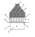
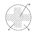
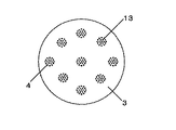
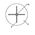
N’/Nを大きくするには、N’を大きくするか、またはNを小さくすればよい。N’を大きくするには、オリフィス孔の配置を密にすることにより、オリフィス孔が最も密に配置されている箇所の10cm2当たりに存在するオリフィス孔の数を大きくすればよい。同数のオリフィス孔を設ける場合、図2の様にオリフィスプレートにオリフィス孔を配置するよりも、例えば、図3や図4の様にオリフィス孔を配置する方が、オリフィス孔を密に配置できる。Nを小さくするには、同様のオリフィス孔の配置でもスラリー容器断面積を大きくすることにより容器断面10cm2当たりに存在するオリフィス孔の平均個数を小さくすればよい。 In order to increase N ′ / N, N ′ may be increased or N may be decreased. In order to increase N ′, it is only necessary to increase the number of orifice holes per 10 cm 2 where the orifice holes are arranged most densely by making the arrangement of the orifice holes dense. When the same number of orifice holes are provided, the orifice holes can be arranged densely, for example, by arranging the orifice holes as shown in FIGS. 3 and 4 rather than arranging the orifice holes in the orifice plate as shown in FIG. In order to reduce N, it is only necessary to reduce the average number of orifice holes per 10 cm 2 of the container cross section by increasing the cross-sectional area of the slurry container even with the same orifice hole arrangement.
好ましい態様としては、直径1〜30cm程度、より好ましくは直径3〜10cm程度のノズルに孔を設け、該ノズルをオリフィスプレートに設置することで、該ノズルをオリフィス孔が最も密に配置されている箇所と擬制でき、N’、Nの調整を容易に行うことができる。 As a preferred embodiment, holes are provided in a nozzle having a diameter of about 1 to 30 cm, more preferably about 3 to 10 cm, and the nozzles are installed in an orifice plate so that the orifice holes are arranged most densely. It is possible to simulate the location and adjust N ′ and N easily.
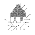
分散相をオリフィス孔を通して連続相に噴出させて均一な液滴を作製する装置としては、例えば図1の装置が考えられる。連続相1を満たしたスラリー容器2内に、オリフィスプレート3にあるオリフィス孔4を通して分散相9を噴出させる。噴出された分散相9は、液柱となった後、液滴5となり、容器内に溜まって液滴溜まり6となって、通路または出口11より他容器または外へ運ばれ、縣濁重合などの後の工程に供される。
As an apparatus for producing uniform droplets by ejecting the dispersed phase to the continuous phase through the orifice holes, for example, the apparatus shown in FIG. 1 can be considered. A dispersed
作製する液滴の粒径は、オリフィス孔径、分散相のオリフィス孔からの噴出速度、分散相の物性、さらには均一性を向上させるために用いる振動など、種々の因子によって決定されるが、代表的には0.05〜5mmであることが好ましい。この範囲の液滴を作製するオリフィス孔径は、代表的には0.001〜2mmが好ましい。 The particle size of the droplet to be prepared is determined by various factors such as the orifice hole diameter, the ejection speed of the dispersed phase from the orifice hole, the physical properties of the dispersed phase, and the vibration used to improve the uniformity. Specifically, it is preferably 0.05 to 5 mm. The orifice hole diameter for producing droplets in this range is typically preferably 0.001 to 2 mm.
オリフィス孔4から噴出される分散相の噴出特性は、分散相の密度をρ、粘度をμ’、オリフィス孔から噴出させたときの噴流速度をu、オリフィス孔径をDとした場合に、Re=ρuD/μ’で表される無次元レイノルズ数によって規定される。オリフィス孔4から噴出される分散相は、均一な液滴を作製するために層流となる必要があることを考慮すると、レイノルズ数の大きさは10〜2000になることが好ましい。
The ejection characteristics of the dispersed phase ejected from the
本発明で用いられる分散相は、連続相に不溶のものであれば特に限定されず、重合性モノマーやその混合物を用いることができる。この重合性モノマーとしては公知のものが使用できるが、例えばスチレン、o−メチルスチレン、m−メチルスチレン、p−メチルスチレン、p−メトキシスチレン、p−フェニルスチレン、p−クロルスチレン、3,4−ジクロルスチレン、エチルスチレン、2,4−ジメチルスチレン、p−n−ブチルスチレン、p−tert−ブチルスチレン、p−n−ヘキシルスチレン、p−n−オクチルスチレン、p−n−ノニルスチレン、p−n−デシルスチレン等のスチレン及びその誘導体類、エチレン、プロピレン、ブチレン、イソブチレン等のエチレン性不飽和モノオレフィン類、ジビニルベンゼン、ジビニルトルエン、ジビニルキシレン、トリビニルベンゼン等のポリビニル芳香族化合物、塩化ビニル、塩化ビニリデン、臭化ブチル、フッ化ビニル等のハロゲン化エステル類、酢酸ビニル、プロピオン酸ビニル、安息香酸ビニル等のカルボン酸のビニルエステル類、メタクリル酸、メタクリル酸メチル、メタクリル酸エチル、メタクリル酸プロピル、メタクリル酸n−ブチル、メタクリル酸n−オクチル、メタクリル酸ドデシル、メタクリル酸ラウリル、メタクリル酸ステアリル、メタクリル酸2−エチルヘキシル、メタクリル酸フェニル、メタクリル酸ジメチルアミノエチル、メタクリル酸ジメチルアミノメチル、メタクリル酸2−ヒドロキシエチル、メタクリル酸2−ヒドロキシプロピル、メタクリル酸グリシジル、メタクリル酸ポリエチレングリコール、ジメタクリル酸エチレングリコール、ジメタクリル酸ジエチレングリコール、ジメタクリル酸ポリエチレングリコール、ジメタクリル酸1,3−ブチレングリコール、ジメタクリル酸グリセロール、トリメタクリル酸トリメチロールプロパン等のメタクリル酸及びその誘導体、アクリル酸、アクリル酸メチル、アクリル酸エチル、アクリル酸プロピル、アクリル酸n−ブチル、アクリル酸イソブチル、アクリル酸n−オクチル、アクリル酸ドデシル、アクリル酸ステアリル、アクリル酸2−エチルヘキシル、アクリル酸クロルエチル、アクリル酸フェニル、アクリル酸メトキシエチル、アクリル酸グリシジル、アクリル酸2−ヒドロキシエチル、アクリル酸2−ヒドロキシプロピル、アクリル酸ポリエチレングリコール、トリアクリル酸ペンタエリスリトール等のアクリル酸及びその誘導体、メタクリル酸アリル、アリルグリシジルエーテル、トリアリルイソシアヌレート、トリアリルシアヌレート等のアリル化合物類、ビニルメチルエーテル、ビニルエチルエーテル、ビニルイソブチルエーテル、ブタンジオールジビニルエーテル、ジエチレングリコールジビニルエーテル等のビニルエーテル類、ビニルメチルケトン、ビニルヘキシルケトン、ビニルイソプロペニルケトン等のビニルケトン類、N−ビニルピロール、N−ビニルカルバゾール、N−ビニルピロリドン等のN−ビニル化合物、ビニルナフタリン類、アクリロニトリル、メタクリルニトリル、アクリルアミド、メタクリルアミド、メチレンビスアクリルアミド、ヒドロキシエチルアクリルアミド、メチロールアクリルアミド等のアクリルアミドもしくはメタクリルアミド類等の重合性単量体が挙げられる。これらは単独あるいは組み合わせて使用することができる。 The dispersed phase used in the present invention is not particularly limited as long as it is insoluble in the continuous phase, and a polymerizable monomer or a mixture thereof can be used. As this polymerizable monomer, known monomers can be used. For example, styrene, o-methylstyrene, m-methylstyrene, p-methylstyrene, p-methoxystyrene, p-phenylstyrene, p-chlorostyrene, 3,4 -Dichlorostyrene, ethylstyrene, 2,4-dimethylstyrene, pn-butylstyrene, p-tert-butylstyrene, pn-hexylstyrene, pn-octylstyrene, pn-nonylstyrene, styrene and its derivatives such as pn-decylstyrene, ethylenically unsaturated monoolefins such as ethylene, propylene, butylene and isobutylene, polyvinyl aromatic compounds such as divinylbenzene, divinyltoluene, divinylxylene and trivinylbenzene, Vinyl chloride, vinylidene chloride, butyl bromide, fluorine Halogenated esters such as vinyl halides, vinyl esters of carboxylic acids such as vinyl acetate, vinyl propionate, vinyl benzoate, methacrylic acid, methyl methacrylate, ethyl methacrylate, propyl methacrylate, n-butyl methacrylate, methacrylic acid N-octyl acid, dodecyl methacrylate, lauryl methacrylate, stearyl methacrylate, 2-ethylhexyl methacrylate, phenyl methacrylate, dimethylaminoethyl methacrylate, dimethylaminomethyl methacrylate, 2-hydroxyethyl methacrylate, 2-methacrylic acid 2- Hydroxypropyl, glycidyl methacrylate, polyethylene glycol methacrylate, ethylene glycol dimethacrylate, diethylene glycol dimethacrylate, polyethylene glycol dimethacrylate Methacrylic acid and its derivatives, such as 1,3-butylene glycol dimethacrylate, glycerol dimethacrylate, trimethylolpropane trimethacrylate, acrylic acid, methyl acrylate, ethyl acrylate, propyl acrylate, n-butyl acrylate , Isobutyl acrylate, n-octyl acrylate, dodecyl acrylate, stearyl acrylate, 2-ethylhexyl acrylate, chloroethyl acrylate, phenyl acrylate, methoxyethyl acrylate, glycidyl acrylate, 2-hydroxyethyl acrylate, acrylic 2-hydroxypropyl acid, polyethylene glycol acrylate, acrylic acid such as pentaerythritol triacrylate and derivatives thereof, allyl methacrylate, allyl glycidyl ether, triallyl iso Allyl compounds such as cyanurate and triallyl cyanurate, vinyl ethers such as vinyl methyl ether, vinyl ethyl ether, vinyl isobutyl ether, butanediol divinyl ether, diethylene glycol divinyl ether, vinyl methyl ketone, vinyl hexyl ketone, vinyl isopropenyl ketone, etc. Vinyl ketones, N-vinyl pyrrole, N-vinyl carbazole, N-vinyl compounds such as N-vinyl pyrrolidone, vinyl naphthalenes, acrylonitrile, methacrylonitrile, acrylamide, methacrylamide, methylene bisacrylamide, hydroxyethyl acrylamide, methylol acrylamide, etc. And polymerizable monomers such as acrylamide or methacrylamide. These can be used alone or in combination.
さらに分散相は、重合性モノマーと、重合開始剤、非重合性液体、線状ポリマー、固体微粒子等との混合物であっても良い。 Further, the dispersed phase may be a mixture of a polymerizable monomer and a polymerization initiator, a non-polymerizable liquid, a linear polymer, solid fine particles and the like.
例えば、重合性モノマーと必要に応じて非重合性液体、線状ポリマー、重合開始剤等の混合物を分散相に使用し、得られた液滴を重合することにより、ポリマービーズを得ることができる。この場合、重合性モノマーは架橋ポリマーを生成しうる重合性モノマーを少なくとも1つ含むのが望ましく、例えば上記例示のものが使用できる。非重合性液体としては、連続相に不溶の液体であれば特に限定されず、例えばトルエン、キシレン、ベンゼン、ヘプタン、オクタン、ヘキサン、シクロヘキサン、酢酸エチル、酢酸ブチル、アルコール類、アセトン、水等を目的に応じて単独あるいは組み合わせて使用することができる。線状ポリマーについても特に制約はないが、例えば上記例示の重合性モノマー単位を含む線状ポリマーがあげられる。なお、分散相に固体微粒子が含まれる場合は、固体微粒子の粒子径は分散相が噴出させられるオリフィス孔より小さい必要がある。 For example, a polymer bead can be obtained by using a mixture of a polymerizable monomer and, if necessary, a non-polymerizable liquid, a linear polymer, a polymerization initiator or the like as a dispersed phase and polymerizing the obtained droplets. . In this case, it is desirable that the polymerizable monomer contains at least one polymerizable monomer capable of forming a crosslinked polymer. For example, those exemplified above can be used. The non-polymerizable liquid is not particularly limited as long as it is insoluble in the continuous phase. For example, toluene, xylene, benzene, heptane, octane, hexane, cyclohexane, ethyl acetate, butyl acetate, alcohols, acetone, water, etc. They can be used alone or in combination depending on the purpose. Although there is no restriction | limiting in particular also about a linear polymer, For example, the linear polymer containing the polymerizable monomer unit of the said illustration is mention | raise | lifted. When the dispersed phase contains solid fine particles, the particle diameter of the solid fine particles needs to be smaller than the orifice hole through which the dispersed phase is ejected.
重合開始剤には公知のものを使用でき、また使用される重合性モノマーに応じて選ぶことが好ましい。例えば、ラウロイルパーオキサイド、過酸化ベンゾイル、t−ブチルパーオキシベンゾエート、イソブチル−t−ブチルパーオキシカーボネート、過安息香酸ブチル、1,1−ビス(t−ブチルパーオキシ)3,3,5−トリメチルシクロヘキサンのような有機過酸化物や、アゾビスイソブチロニトリル、アゾビスジメチルバレロニトリル、アゾビストリメチルペンタン、アゾビスシアノバレリアン酸などのアゾ化合物、過硫酸塩、過酸化水素、又はハイドロパーオキサイド等の水溶性ラジカル重合開始剤が使用でき、またこれらを併用しても何ら差し支えない。なお、重合開始剤は、分散相に直接混合しても良いし、別途溶液やスラリーとして連続相に加えても良い。 A well-known thing can be used for a polymerization initiator, It is preferable to select according to the polymerizable monomer used. For example, lauroyl peroxide, benzoyl peroxide, t-butyl peroxybenzoate, isobutyl-t-butyl peroxycarbonate, butyl perbenzoate, 1,1-bis (t-butylperoxy) 3,3,5-trimethyl Organic peroxides such as cyclohexane, azo compounds such as azobisisobutyronitrile, azobisdimethylvaleronitrile, azobistrimethylpentane, azobiscyanovaleric acid, persulfates, hydrogen peroxide, or hydroperoxide Water-soluble radical polymerization initiators such as these can be used, and they can be used in combination. The polymerization initiator may be directly mixed with the dispersed phase, or may be separately added to the continuous phase as a solution or slurry.
連続相に用いる溶媒は特に限定されないが、例えば水や水溶液が経済的で環境負荷が小さく好ましい。また連続相には分散剤や塩類を含有させてもよい。分散剤は、縣濁重合で一般に使用されるものを用いることができ、例えば、ゼラチン、ポリビニルアルコール、ポリビニルピロリドン、ポリアクリルアミド、デンプン等の高分子分散剤、燐酸カルシウム、ハイドロキシアパタイト、ピロリン酸マグネシウム等の連続相に難溶な無機塩、カルボキシメチルセルロース、ヒドロキシエチルセルロース等のセルロースエーテル類を用いることができる。また、分散剤として連続相に難溶な無機塩を用いる場合には、α−オレフィンスルホン酸ソーダ、ドデシルベンゼンスルホン酸ソーダ等のアニオン界面活性剤を併用するのが好ましい。 The solvent used for the continuous phase is not particularly limited. For example, water or an aqueous solution is preferable because it is economical and has a low environmental burden. The continuous phase may contain a dispersant and salts. As the dispersant, those commonly used in suspension polymerization can be used. For example, gelatin, polyvinyl alcohol, polyvinylpyrrolidone, polyacrylamide, starch and other polymer dispersants, calcium phosphate, hydroxyapatite, magnesium pyrophosphate, etc. Inorganic salts that are hardly soluble in the continuous phase, and cellulose ethers such as carboxymethyl cellulose and hydroxyethyl cellulose can be used. In addition, when an inorganic salt that is hardly soluble in the continuous phase is used as a dispersant, it is preferable to use an anionic surfactant such as α-olefin sulfonic acid soda and dodecylbenzene sulfonic acid soda in combination.
より均一な液滴を作製する方法として、室8に加振装置を設置し、オリフィス孔から噴出する分散相に振動を与えてもよい。分散相に与える振動数は、作製する液滴の粒径にもよるが、液滴の粒径が0.05〜5mmの場合、100〜10000Hzが好ましい。
As a method for producing more uniform droplets, a vibration device may be installed in the
本発明で得られた液滴は、連続相と共に通路または出口から排出され、懸濁重合等の後の工程に供される。例えば、分散相としてスチレンを用いた場合、液滴としてスチレンモノマーを含んだスラリーが得られ、これを重合缶へ移し、例えば、攪拌下98℃2時間重合反応を行うことでスチレンビーズが得られる。 The droplets obtained in the present invention are discharged from the passage or outlet together with the continuous phase, and are subjected to subsequent processes such as suspension polymerization. For example, when styrene is used as the dispersed phase, a slurry containing a styrene monomer is obtained as droplets, which are transferred to a polymerization can and, for example, styrene beads are obtained by performing a polymerization reaction at 98 ° C. for 2 hours with stirring. .
(実施例1)
実施例で用いた液滴生成装置を図5に示した。スラリー容器は円筒状で断面積314cm2(内径20cm)のものを用いた。オリフィス孔が最も密に配置されている箇所の10cm2当たりに存在するオリフィス孔の数N’が145.4である直径4cmのノズル(オリフィス孔の孔径0.1mm)2つをオリフィスプレートに設置した。総オリフィス孔数は296であり、このとき、容器断面10cm2当たりに存在するオリフィス孔の平均個数Nは9.4となり、N’/Nは15.4となった。
(Example 1)
The droplet generator used in the examples is shown in FIG. The slurry container was cylindrical and had a cross-sectional area of 314 cm 2 (inner diameter 20 cm). Two nozzles with a diameter of 4 cm (orifice hole diameter of 0.1 mm) having an orifice hole number N ′ of 145.4 per 10 cm 2 of the most densely arranged orifice holes are installed in the orifice plate. did. The total number of orifice holes was 296. At this time, the average number N of orifice holes existing per 10 cm 2 of the cross section of the container was 9.4, and N ′ / N was 15.4.
スラリー容器に19.5L/時のポリビニルアルコール水溶液(ポリビニルアルコール濃度は320ppm)を供給しておき、分散相入口から22.3L/時、レイノルズ数が310となる条件でスチレンを供給し、加振機で1990Hzの振動を与えて、粒径260μmの均一な液滴を作製した。このとき、V×(N’/N)=0.14となり、オリフィス孔から液滴溜まりまでの最短距離(XNE)は9mmとなって、噴出孔から噴出された分散相が液滴になる前あるいはなった直後の不安定な液滴の状態で液滴溜まりと衝突することはなかった。得られた液滴を攪拌下2時間、98℃で重合反応を行って得られた粒子は、98%以上の割合で均一なスチレンのポリマービーズが得られた。
(実施例2)
スラリー容器を断面積707cm2(内径30cm)にした以外は、実施例1と同様の条件で、スチレンの液滴を作製した。容器断面10cm2当たりに存在するオリフィス孔の平均個数Nは4.2となり。N’/Nは34.6、V×(N’/N)=0.32となった。
A 19.5 L / hour polyvinyl alcohol aqueous solution (polyvinyl alcohol concentration is 320 ppm) is supplied to the slurry container, and styrene is supplied from the inlet of the dispersed phase at 22.3 L / hour and a Reynolds number of 310. A uniform drop having a particle size of 260 μm was produced by applying vibration at 1990 Hz with a machine. At this time, V × (N ′ / N) = 0.14, the shortest distance (X NE ) from the orifice hole to the droplet reservoir is 9 mm, and the dispersed phase ejected from the ejection hole becomes a droplet. It did not collide with the droplet reservoir in the state of an unstable droplet immediately before or after it became. Uniform styrene polymer beads were obtained from the particles obtained by subjecting the obtained droplets to a polymerization reaction at 98 ° C. for 2 hours with stirring at a rate of 98% or more.
(Example 2)
Styrene droplets were produced under the same conditions as in Example 1 except that the slurry container had a cross-sectional area of 707 cm 2 (inner diameter: 30 cm). The average number N of orifice holes present per 10 cm 2 of the container cross section is 4.2. N ′ / N was 34.6, and V × (N ′ / N) = 0.32.
オリフィス孔から液滴溜まりまでの最短距離(XNE)は94mmとなって、噴出孔から噴出された分散相が液滴になる前あるいはなった直後の不安定な液滴の状態で液滴溜まりと衝突することはなかった。得られた液滴を実施例と同様の条件で重合した結果、98%以上の割合で均一なスチレンのポリマービーズが得られた。
(比較例1)
総オリフィス孔数296、孔径0.1mmのオリフィス孔を、直径19cmのオリフィスプレートに等間隔配置する以外は全て実施例1と同様の条件で、スチレンの液滴を作製する。オリフィス孔が最も密に配置されている箇所の10cm2当たりに存在するオリフィス孔の数N’は9.4、容器断面10cm2当たりに存在するオリフィス孔の平均個数Nは10.4、N’/Nは0.9であり、V×(N’/N)=0.0082となる。オリフィス孔から液滴溜まりまでの最短距離(XNE)は、0mmとなって、噴出孔から噴出された分散相が液滴になる前、或いは、なった直後の不安定な液滴の状態で液滴溜まりと衝突する。得られた液滴を実施例と同様の条件で重合すると、概ね70%の割合で均一なスチレンのポリマービーズが得られる。
(実施例3)
実施例で用いた液滴生成装置を図5に示した。スラリー容器は円筒状で断面積707cm2(内径30cm)のものを用い、孔が148存在するオリフィス孔が最も密に配置されている箇所の10cm2当たりに存在するオリフィス孔の数N’が145.4である直径4cmのノズル(オリフィス孔の孔径0.1mm)3つをオリフィスプレートに設置した。総オリフィス孔数は444であり、このとき、容器断面10cm2当たりに存在するオリフィス孔の平均個数Nは6.3となり、N’/Nは23.2となった。
The shortest distance (X NE ) from the orifice hole to the droplet reservoir is 94 mm, and the droplet reservoir is in an unstable droplet state before or just after the dispersed phase ejected from the ejection hole becomes a droplet. Did not collide with. As a result of polymerizing the obtained droplets under the same conditions as in Examples, uniform styrene polymer beads were obtained at a ratio of 98% or more.
(Comparative Example 1)
Styrene droplets are produced under the same conditions as in Example 1 except that orifice holes with a total orifice number of 296 and a hole diameter of 0.1 mm are arranged at equal intervals on an orifice plate with a diameter of 19 cm. The number N ′ of orifice holes present per 10 cm 2 where the orifice holes are most closely arranged is 9.4, the average number N of orifice holes present per 10 cm 2 of the container cross section is 10.4, N ′ / N is 0.9, and V × (N ′ / N) = 0.0006. The shortest distance (X NE ) from the orifice hole to the droplet reservoir is 0 mm, and the unstable phase immediately after the dispersed phase ejected from the ejection hole becomes a droplet. Collides with droplet reservoir. When the obtained droplets are polymerized under the same conditions as in the examples, uniform polymer beads of styrene are obtained at a ratio of approximately 70%.
(Example 3)
The droplet generator used in the examples is shown in FIG. The slurry container is cylindrical and has a cross-sectional area of 707 cm 2 (inner diameter: 30 cm), and the number N ′ of orifice holes present per 10 cm 2 where the orifice holes having 148 holes are arranged most closely is 145. 4 nozzles having a diameter of 4 cm (orifice hole diameter 0.1 mm) were placed on the orifice plate. The total number of orifice holes was 444. At this time, the average number N of orifice holes present per 10 cm 2 of the container cross section was 6.3, and N ′ / N was 23.2.
スラリー容器に29.3L/時のポリビニルアルコール水溶液(ポリビニルアルコール濃度は320ppm)を供給しておき、分散相入口から33.4L/時、レイノルズ数が310となる条件でスチレンを供給し、加振機で1990Hzの振動を与えて、粒径260μmの均一な液滴を作製した。このとき、V×(N’/N)=0.21となり、オリフィス孔から液滴溜まりまでの最短距離(XNE)は35mmとなって、噴出孔から噴出された分散相が液滴になる前あるいはなった直後の不安定な液滴の状態で液滴溜まりと衝突することはなかった。得られた液滴を攪拌下2時間、98℃で重合反応を行って得られた粒子は、98%以上の割合で均一なスチレンのポリマービーズが得られた。
(実施例4)
総オリフィス孔数542、孔が271存在するオリフィス孔が最も密に配置されている箇所の10cm2当たりに存在するオリフィス孔の数N’が266.2である直径4cmのノズル(オリフィス孔の孔径0.1mm)2つをオリフィスプレートに設置し、容器断面10cm2当たりに存在するオリフィス孔の平均個数Nを7.7、N’/Nを34.6とした以外は全て実施例3と同様の条件で、スチレンの液滴を作製した。このとき、V×(N’/N)=0.32となり、実施例3より液滴作製量が増えたにもかかわらず、オリフィス孔から液滴溜まりまでの最短距離(XNE)は実施例2よりも大きい82mmとなって、噴出孔から噴出された分散相が液滴になる前あるいはなった直後の不安定な液滴の状態で液滴溜まりと衝突することはなかった。得られた液滴を実施例と同様の条件で重合した結果、98%以上の割合で均一なスチレンのポリマービーズが得られた。
(比較例2)
スラリー容器の内径を14cm、断面積154cm2、容器断面10cm2当たりに存在するオリフィス孔の平均個数Nは28.8、N’/Nは5.04となること以外は全て実施例3と同様の条件で、スチレンの液滴を作製する。このとき、V×(N’/N)=0.046となる。オリフィス孔から液滴溜まりの最短距離は0mmとなって、噴出孔から噴出された分散相が液滴になる前あるいはなった直後の不安定な液滴の状態で液滴溜まりと衝突する。得られた液滴を実施例と同様の条件で重合した結果、概ね80%の割合で均一なスチレンのポリマービーズが得られる。
A 29.3 L / hour polyvinyl alcohol aqueous solution (polyvinyl alcohol concentration is 320 ppm) is supplied to the slurry container, and styrene is supplied from the dispersed phase inlet at 33.4 L / hour and a Reynolds number of 310, and the vibration is applied. A uniform drop having a particle size of 260 μm was produced by applying vibration at 1990 Hz with a machine. At this time, V × (N ′ / N) = 0.21, the shortest distance (X NE ) from the orifice hole to the droplet reservoir is 35 mm, and the dispersed phase ejected from the ejection hole becomes a droplet. It did not collide with the droplet reservoir in the state of an unstable droplet immediately before or after it became. Uniform styrene polymer beads were obtained from the particles obtained by subjecting the obtained droplets to a polymerization reaction at 98 ° C. for 2 hours with stirring at a rate of 98% or more.
Example 4
Nozzle with a diameter of 4 cm having a total orifice hole number of 542 and an orifice hole number of N ′ of 266.2 per 10 cm 2 where the orifice holes having 271 holes are most closely arranged (diameter of the orifice hole) 0.1 mm) are set on the orifice plate, and all are the same as in Example 3 except that the average number N of orifice holes per 10 cm 2 of the container cross section is 7.7 and N ′ / N is 34.6. Under these conditions, styrene droplets were prepared. At this time, V × (N ′ / N) = 0.32, and the shortest distance (X NE ) from the orifice hole to the droplet reservoir is the example even though the droplet production amount is increased as compared with the example 3. The dispersion phase ejected from the ejection hole did not collide with the droplet reservoir in an unstable droplet state before or immediately after becoming a droplet. As a result of polymerizing the obtained droplets under the same conditions as in Examples, uniform styrene polymer beads were obtained at a ratio of 98% or more.
(Comparative Example 2)
14cm internal diameter of the slurry container, the cross-sectional area 154cm 2, the average number N of the orifice hole present per
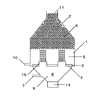
1 連続相
2 スラリー容器
3 オリフィスプレート
4 オリフィス孔
5 液滴
6 液滴溜まり
7 分散相入口
8 室
9 分散相
10 連続層入口
11 通路または出口
12 距離
13 オリフィス孔最密箇所
14 加振機
15 ノズル
DESCRIPTION OF SYMBOLS 1 Continuous phase 2
Claims (4)
V×(N’/N)≧0.05 …(1) In an apparatus for producing droplets by ejecting a dispersed phase from an orifice hole into a slurry container filled with a continuous phase, the number of orifice holes present per 10 cm 2 where the orifice holes are most closely arranged is calculated. N ′, where N is the average number of orifice holes per 10 cm 2 of the cross section of the container, and V [mm 3 ] is the volume of the produced droplets, V, N ′ and N are represented by the formula (1). A droplet manufacturing apparatus characterized by satisfying the relationship.
V × (N ′ / N) ≧ 0.05 (1)
V×(N’/N)≧0.2 …(2) In an apparatus for producing droplets by ejecting a dispersed phase from an orifice hole into a slurry container filled with a continuous phase, the number of orifice holes present per 10 cm 2 where the orifice holes are most closely arranged is calculated. N ′, where N is the average number of orifice holes per 10 cm 2 of the cross section of the container, and V [mm 3 ] is the volume of the produced droplets, V, N ′ and N are represented by the formula (2). The droplet manufacturing apparatus according to claim 1, wherein the relationship is satisfied.
V × (N ′ / N) ≧ 0.2 (2)
Priority Applications (1)
| Application Number | Priority Date | Filing Date | Title |
|---|---|---|---|
| JP2004119831A JP2005296883A (en) | 2004-04-15 | 2004-04-15 | Droplet production apparatus |
Applications Claiming Priority (1)
| Application Number | Priority Date | Filing Date | Title |
|---|---|---|---|
| JP2004119831A JP2005296883A (en) | 2004-04-15 | 2004-04-15 | Droplet production apparatus |
Publications (1)
| Publication Number | Publication Date |
|---|---|
| JP2005296883A true JP2005296883A (en) | 2005-10-27 |
Family
ID=35329074
Family Applications (1)
| Application Number | Title | Priority Date | Filing Date |
|---|---|---|---|
| JP2004119831A Pending JP2005296883A (en) | 2004-04-15 | 2004-04-15 | Droplet production apparatus |
Country Status (1)
| Country | Link |
|---|---|
| JP (1) | JP2005296883A (en) |
Cited By (1)
| Publication number | Priority date | Publication date | Assignee | Title |
|---|---|---|---|---|
| WO2010146778A1 (en) * | 2009-06-16 | 2010-12-23 | ソニー株式会社 | Substance mixing device and substance mixing method |
-
2004
- 2004-04-15 JP JP2004119831A patent/JP2005296883A/en active Pending
Cited By (6)
| Publication number | Priority date | Publication date | Assignee | Title |
|---|---|---|---|---|
| WO2010146778A1 (en) * | 2009-06-16 | 2010-12-23 | ソニー株式会社 | Substance mixing device and substance mixing method |
| JP2011000493A (en) * | 2009-06-16 | 2011-01-06 | Sony Corp | Substance mixing device and substance mixing method |
| KR20120027011A (en) * | 2009-06-16 | 2012-03-20 | 소니 주식회사 | Substance mixing device and substance mixing method |
| US9233346B2 (en) | 2009-06-16 | 2016-01-12 | Sony Corporation | Droplet collision substance mixing apparatus and droplet collision substance mixing method |
| KR101726709B1 (en) * | 2009-06-16 | 2017-04-13 | 소니 주식회사 | Substance mixing device and substance mixing method |
| US11020717B2 (en) | 2009-06-16 | 2021-06-01 | Sony Corporation | Droplet collision substance mixing apparatus and droplet collision substance mixing method |
Similar Documents
| Publication | Publication Date | Title |
|---|---|---|
| EP0051210B2 (en) | Process for preparing uniform size spheroidal polymer beads | |
| US9415530B2 (en) | Method of producing uniform polymer beads of various sizes | |
| AU2014298550B2 (en) | Reverse-phase polymerisation process | |
| EP2711074B1 (en) | Method and apparatus for preparing polymer beads of uniform particle size by suspension polymerisation | |
| WO2014149771A1 (en) | Method of producing uniform, fine polymer beads by vibration jetting | |
| US6610798B1 (en) | Controlled suspension polymerization process without mechanical agitation | |
| JP7271385B2 (en) | Method for producing O/W emulsion and method for producing fine particles | |
| KR101393969B1 (en) | Method for producing aqueous polymer dispersion | |
| US5061741A (en) | Method for preparing an oil-in-water type uniform dispersion of liquid droplets and polymerization method for preparing polymer beads of uniform particle size | |
| EP1389625B1 (en) | Method of dispersion of a non-newtonian fluid | |
| US6117939A (en) | Free radical miniemulsion polymerization with low shear and heat exchanger | |
| JP2005296883A (en) | Droplet production apparatus | |
| JP5091784B2 (en) | Emulsion production apparatus, monodisperse fine particle production apparatus, emulsion production method, and monodisperse fine particle production method | |
| EP1591158B1 (en) | Controlled shear and turbulence flow pattern within a liquid phase in a vessel | |
| JPH02305802A (en) | Method and apparatus for suspension polymerization | |
| US6727328B1 (en) | Controlled shear and turbulence flow pattern within a liquid in a vessel | |
| JP2001162147A (en) | Uniform droplet generator | |
| JPH03249931A (en) | Production of oil-in-water type uniform droplets dispersion and method for polymerizing uniform-diameter-polymer beads | |
| JP4706181B2 (en) | Droplet production equipment | |
| JP3328033B2 (en) | Suspension polymerization method | |
| JP2003192706A (en) | Method for producing oil-in-water dispersion | |
| JPS5891701A (en) | Continuous suspension polymerization method | |
| WO2023286822A1 (en) | Expandable methyl methacrylate-based resin particles, expanded methyl methacrylate-based resin particles, methyl methacrylate-based resin foam molded article, evaporative pattern, and method for producing expandable methyl methacrylate-based resin particles | |
| JPH11130816A (en) | Production of styrene-based particle and foamable styrene-based particle | |
| JP2004113933A (en) | Emulsion manufacturing method |
Legal Events
| Date | Code | Title | Description |
|---|---|---|---|
| A621 | Written request for application examination |
Free format text: JAPANESE INTERMEDIATE CODE: A621 Effective date: 20070226 |
|
| A977 | Report on retrieval |
Effective date: 20091022 Free format text: JAPANESE INTERMEDIATE CODE: A971007 |
|
| A131 | Notification of reasons for refusal |
Free format text: JAPANESE INTERMEDIATE CODE: A131 Effective date: 20091104 |
|
| A02 | Decision of refusal |
Effective date: 20100302 Free format text: JAPANESE INTERMEDIATE CODE: A02 |