JP2005296845A - Liquid droplet forming apparatus - Google Patents
Liquid droplet forming apparatus Download PDFInfo
- Publication number
- JP2005296845A JP2005296845A JP2004118052A JP2004118052A JP2005296845A JP 2005296845 A JP2005296845 A JP 2005296845A JP 2004118052 A JP2004118052 A JP 2004118052A JP 2004118052 A JP2004118052 A JP 2004118052A JP 2005296845 A JP2005296845 A JP 2005296845A
- Authority
- JP
- Japan
- Prior art keywords
- plate
- droplet
- liquid
- droplets
- nozzle
- Prior art date
- Legal status (The legal status is an assumption and is not a legal conclusion. Google has not performed a legal analysis and makes no representation as to the accuracy of the status listed.)
- Granted
Links
- 239000007788 liquid Substances 0.000 title claims abstract description 95
- 238000004519 manufacturing process Methods 0.000 claims abstract description 41
- 238000005192 partition Methods 0.000 claims abstract description 14
- 239000000178 monomer Substances 0.000 claims description 14
- 229920000642 polymer Polymers 0.000 claims description 9
- 239000011324 bead Substances 0.000 claims description 4
- 239000002245 particle Substances 0.000 abstract description 27
- 239000003223 protective agent Substances 0.000 abstract description 3
- PPBRXRYQALVLMV-UHFFFAOYSA-N Styrene Chemical compound C=CC1=CC=CC=C1 PPBRXRYQALVLMV-UHFFFAOYSA-N 0.000 description 32
- 239000002002 slurry Substances 0.000 description 25
- 239000004372 Polyvinyl alcohol Substances 0.000 description 9
- 239000007864 aqueous solution Substances 0.000 description 9
- 238000000034 method Methods 0.000 description 9
- 229920002451 polyvinyl alcohol Polymers 0.000 description 9
- 235000019422 polyvinyl alcohol Nutrition 0.000 description 9
- 239000002270 dispersing agent Substances 0.000 description 7
- 230000003993 interaction Effects 0.000 description 5
- -1 pn-butylstyrene Chemical compound 0.000 description 4
- 239000003505 polymerization initiator Substances 0.000 description 4
- UHOVQNZJYSORNB-UHFFFAOYSA-N Benzene Chemical compound C1=CC=CC=C1 UHOVQNZJYSORNB-UHFFFAOYSA-N 0.000 description 3
- XEKOWRVHYACXOJ-UHFFFAOYSA-N Ethyl acetate Chemical compound CCOC(C)=O XEKOWRVHYACXOJ-UHFFFAOYSA-N 0.000 description 3
- MHAJPDPJQMAIIY-UHFFFAOYSA-N Hydrogen peroxide Chemical compound OO MHAJPDPJQMAIIY-UHFFFAOYSA-N 0.000 description 3
- 239000002202 Polyethylene glycol Substances 0.000 description 3
- YXFVVABEGXRONW-UHFFFAOYSA-N Toluene Chemical compound CC1=CC=CC=C1 YXFVVABEGXRONW-UHFFFAOYSA-N 0.000 description 3
- 239000002253 acid Substances 0.000 description 3
- 238000004140 cleaning Methods 0.000 description 3
- 230000000052 comparative effect Effects 0.000 description 3
- 238000009826 distribution Methods 0.000 description 3
- 239000010419 fine particle Substances 0.000 description 3
- 238000012423 maintenance Methods 0.000 description 3
- 239000000203 mixture Substances 0.000 description 3
- VLKZOEOYAKHREP-UHFFFAOYSA-N n-Hexane Chemical compound CCCCCC VLKZOEOYAKHREP-UHFFFAOYSA-N 0.000 description 3
- 229920001223 polyethylene glycol Polymers 0.000 description 3
- 239000007787 solid Substances 0.000 description 3
- MYRTYDVEIRVNKP-UHFFFAOYSA-N 1,2-Divinylbenzene Chemical compound C=CC1=CC=CC=C1C=C MYRTYDVEIRVNKP-UHFFFAOYSA-N 0.000 description 2
- UAJRSHJHFRVGMG-UHFFFAOYSA-N 1-ethenyl-4-methoxybenzene Chemical compound COC1=CC=C(C=C)C=C1 UAJRSHJHFRVGMG-UHFFFAOYSA-N 0.000 description 2
- OZAIFHULBGXAKX-UHFFFAOYSA-N 2-(2-cyanopropan-2-yldiazenyl)-2-methylpropanenitrile Chemical compound N#CC(C)(C)N=NC(C)(C)C#N OZAIFHULBGXAKX-UHFFFAOYSA-N 0.000 description 2
- SMZOUWXMTYCWNB-UHFFFAOYSA-N 2-(2-methoxy-5-methylphenyl)ethanamine Chemical compound COC1=CC=C(C)C=C1CCN SMZOUWXMTYCWNB-UHFFFAOYSA-N 0.000 description 2
- NIXOWILDQLNWCW-UHFFFAOYSA-N 2-Propenoic acid Natural products OC(=O)C=C NIXOWILDQLNWCW-UHFFFAOYSA-N 0.000 description 2
- XFCMNSHQOZQILR-UHFFFAOYSA-N 2-[2-(2-methylprop-2-enoyloxy)ethoxy]ethyl 2-methylprop-2-enoate Chemical compound CC(=C)C(=O)OCCOCCOC(=O)C(C)=C XFCMNSHQOZQILR-UHFFFAOYSA-N 0.000 description 2
- CSCPPACGZOOCGX-UHFFFAOYSA-N Acetone Chemical compound CC(C)=O CSCPPACGZOOCGX-UHFFFAOYSA-N 0.000 description 2
- HRPVXLWXLXDGHG-UHFFFAOYSA-N Acrylamide Chemical compound NC(=O)C=C HRPVXLWXLXDGHG-UHFFFAOYSA-N 0.000 description 2
- SOGAXMICEFXMKE-UHFFFAOYSA-N Butylmethacrylate Chemical compound CCCCOC(=O)C(C)=C SOGAXMICEFXMKE-UHFFFAOYSA-N 0.000 description 2
- XDTMQSROBMDMFD-UHFFFAOYSA-N Cyclohexane Chemical compound C1CCCCC1 XDTMQSROBMDMFD-UHFFFAOYSA-N 0.000 description 2
- WOBHKFSMXKNTIM-UHFFFAOYSA-N Hydroxyethyl methacrylate Chemical compound CC(=C)C(=O)OCCO WOBHKFSMXKNTIM-UHFFFAOYSA-N 0.000 description 2
- CERQOIWHTDAKMF-UHFFFAOYSA-N Methacrylic acid Chemical compound CC(=C)C(O)=O CERQOIWHTDAKMF-UHFFFAOYSA-N 0.000 description 2
- BAPJBEWLBFYGME-UHFFFAOYSA-N Methyl acrylate Chemical compound COC(=O)C=C BAPJBEWLBFYGME-UHFFFAOYSA-N 0.000 description 2
- IMNFDUFMRHMDMM-UHFFFAOYSA-N N-Heptane Chemical compound CCCCCCC IMNFDUFMRHMDMM-UHFFFAOYSA-N 0.000 description 2
- CDBYLPFSWZWCQE-UHFFFAOYSA-L Sodium Carbonate Chemical compound [Na+].[Na+].[O-]C([O-])=O CDBYLPFSWZWCQE-UHFFFAOYSA-L 0.000 description 2
- 230000001133 acceleration Effects 0.000 description 2
- 230000008602 contraction Effects 0.000 description 2
- GMSCBRSQMRDRCD-UHFFFAOYSA-N dodecyl 2-methylprop-2-enoate Chemical compound CCCCCCCCCCCCOC(=O)C(C)=C GMSCBRSQMRDRCD-UHFFFAOYSA-N 0.000 description 2
- FJKIXWOMBXYWOQ-UHFFFAOYSA-N ethenoxyethane Chemical compound CCOC=C FJKIXWOMBXYWOQ-UHFFFAOYSA-N 0.000 description 2
- STVZJERGLQHEKB-UHFFFAOYSA-N ethylene glycol dimethacrylate Substances CC(=C)C(=O)OCCOC(=O)C(C)=C STVZJERGLQHEKB-UHFFFAOYSA-N 0.000 description 2
- 239000007789 gas Substances 0.000 description 2
- 230000005484 gravity Effects 0.000 description 2
- 238000009434 installation Methods 0.000 description 2
- 238000005259 measurement Methods 0.000 description 2
- FQPSGWSUVKBHSU-UHFFFAOYSA-N methacrylamide Chemical compound CC(=C)C(N)=O FQPSGWSUVKBHSU-UHFFFAOYSA-N 0.000 description 2
- 230000000644 propagated effect Effects 0.000 description 2
- 239000002994 raw material Substances 0.000 description 2
- 150000003839 salts Chemical class 0.000 description 2
- 229920001567 vinyl ester resin Polymers 0.000 description 2
- 125000000391 vinyl group Chemical group [H]C([*])=C([H])[H] 0.000 description 2
- 229920002554 vinyl polymer Polymers 0.000 description 2
- QEQBMZQFDDDTPN-UHFFFAOYSA-N (2-methylpropan-2-yl)oxy benzenecarboperoxoate Chemical compound CC(C)(C)OOOC(=O)C1=CC=CC=C1 QEQBMZQFDDDTPN-UHFFFAOYSA-N 0.000 description 1
- UUGXDEDGRPYWHG-UHFFFAOYSA-N (dimethylamino)methyl 2-methylprop-2-enoate Chemical compound CN(C)COC(=O)C(C)=C UUGXDEDGRPYWHG-UHFFFAOYSA-N 0.000 description 1
- WVAFEFUPWRPQSY-UHFFFAOYSA-N 1,2,3-tris(ethenyl)benzene Chemical group C=CC1=CC=CC(C=C)=C1C=C WVAFEFUPWRPQSY-UHFFFAOYSA-N 0.000 description 1
- ZJQIXGGEADDPQB-UHFFFAOYSA-N 1,2-bis(ethenyl)-3,4-dimethylbenzene Chemical group CC1=CC=C(C=C)C(C=C)=C1C ZJQIXGGEADDPQB-UHFFFAOYSA-N 0.000 description 1
- BJQFWAQRPATHTR-UHFFFAOYSA-N 1,2-dichloro-4-ethenylbenzene Chemical compound ClC1=CC=C(C=C)C=C1Cl BJQFWAQRPATHTR-UHFFFAOYSA-N 0.000 description 1
- VDYWHVQKENANGY-UHFFFAOYSA-N 1,3-Butyleneglycol dimethacrylate Chemical compound CC(=C)C(=O)OC(C)CCOC(=O)C(C)=C VDYWHVQKENANGY-UHFFFAOYSA-N 0.000 description 1
- MWZJGRDWJVHRDV-UHFFFAOYSA-N 1,4-bis(ethenoxy)butane Chemical compound C=COCCCCOC=C MWZJGRDWJVHRDV-UHFFFAOYSA-N 0.000 description 1
- MPPPKRYCTPRNTB-UHFFFAOYSA-N 1-bromobutane Chemical compound CCCCBr MPPPKRYCTPRNTB-UHFFFAOYSA-N 0.000 description 1
- KTZVZZJJVJQZHV-UHFFFAOYSA-N 1-chloro-4-ethenylbenzene Chemical compound ClC1=CC=C(C=C)C=C1 KTZVZZJJVJQZHV-UHFFFAOYSA-N 0.000 description 1
- SAMJGBVVQUEMGC-UHFFFAOYSA-N 1-ethenoxy-2-(2-ethenoxyethoxy)ethane Chemical compound C=COCCOCCOC=C SAMJGBVVQUEMGC-UHFFFAOYSA-N 0.000 description 1
- OZCMOJQQLBXBKI-UHFFFAOYSA-N 1-ethenoxy-2-methylpropane Chemical compound CC(C)COC=C OZCMOJQQLBXBKI-UHFFFAOYSA-N 0.000 description 1
- OEVVKKAVYQFQNV-UHFFFAOYSA-N 1-ethenyl-2,4-dimethylbenzene Chemical compound CC1=CC=C(C=C)C(C)=C1 OEVVKKAVYQFQNV-UHFFFAOYSA-N 0.000 description 1
- NVZWEEGUWXZOKI-UHFFFAOYSA-N 1-ethenyl-2-methylbenzene Chemical compound CC1=CC=CC=C1C=C NVZWEEGUWXZOKI-UHFFFAOYSA-N 0.000 description 1
- JZHGRUMIRATHIU-UHFFFAOYSA-N 1-ethenyl-3-methylbenzene Chemical compound CC1=CC=CC(C=C)=C1 JZHGRUMIRATHIU-UHFFFAOYSA-N 0.000 description 1
- CTXUTPWZJZHRJC-UHFFFAOYSA-N 1-ethenylpyrrole Chemical compound C=CN1C=CC=C1 CTXUTPWZJZHRJC-UHFFFAOYSA-N 0.000 description 1
- QEDJMOONZLUIMC-UHFFFAOYSA-N 1-tert-butyl-4-ethenylbenzene Chemical compound CC(C)(C)C1=CC=C(C=C)C=C1 QEDJMOONZLUIMC-UHFFFAOYSA-N 0.000 description 1
- IGGDKDTUCAWDAN-UHFFFAOYSA-N 1-vinylnaphthalene Chemical class C1=CC=C2C(C=C)=CC=CC2=C1 IGGDKDTUCAWDAN-UHFFFAOYSA-N 0.000 description 1
- BJELTSYBAHKXRW-UHFFFAOYSA-N 2,4,6-triallyloxy-1,3,5-triazine Chemical compound C=CCOC1=NC(OCC=C)=NC(OCC=C)=N1 BJELTSYBAHKXRW-UHFFFAOYSA-N 0.000 description 1
- STMDPCBYJCIZOD-UHFFFAOYSA-N 2-(2,4-dinitroanilino)-4-methylpentanoic acid Chemical compound CC(C)CC(C(O)=O)NC1=CC=C([N+]([O-])=O)C=C1[N+]([O-])=O STMDPCBYJCIZOD-UHFFFAOYSA-N 0.000 description 1
- OEPOKWHJYJXUGD-UHFFFAOYSA-N 2-(3-phenylmethoxyphenyl)-1,3-thiazole-4-carbaldehyde Chemical compound O=CC1=CSC(C=2C=C(OCC=3C=CC=CC=3)C=CC=2)=N1 OEPOKWHJYJXUGD-UHFFFAOYSA-N 0.000 description 1
- JKNCOURZONDCGV-UHFFFAOYSA-N 2-(dimethylamino)ethyl 2-methylprop-2-enoate Chemical compound CN(C)CCOC(=O)C(C)=C JKNCOURZONDCGV-UHFFFAOYSA-N 0.000 description 1
- GOXQRTZXKQZDDN-UHFFFAOYSA-N 2-Ethylhexyl acrylate Chemical compound CCCCC(CC)COC(=O)C=C GOXQRTZXKQZDDN-UHFFFAOYSA-N 0.000 description 1
- WHBAYNMEIXUTJV-UHFFFAOYSA-N 2-chloroethyl prop-2-enoate Chemical compound ClCCOC(=O)C=C WHBAYNMEIXUTJV-UHFFFAOYSA-N 0.000 description 1
- WBIQQQGBSDOWNP-UHFFFAOYSA-N 2-dodecylbenzenesulfonic acid Chemical compound CCCCCCCCCCCCC1=CC=CC=C1S(O)(=O)=O WBIQQQGBSDOWNP-UHFFFAOYSA-N 0.000 description 1
- WDQMWEYDKDCEHT-UHFFFAOYSA-N 2-ethylhexyl 2-methylprop-2-enoate Chemical compound CCCCC(CC)COC(=O)C(C)=C WDQMWEYDKDCEHT-UHFFFAOYSA-N 0.000 description 1
- OMIGHNLMNHATMP-UHFFFAOYSA-N 2-hydroxyethyl prop-2-enoate Chemical compound OCCOC(=O)C=C OMIGHNLMNHATMP-UHFFFAOYSA-N 0.000 description 1
- HFCUBKYHMMPGBY-UHFFFAOYSA-N 2-methoxyethyl prop-2-enoate Chemical compound COCCOC(=O)C=C HFCUBKYHMMPGBY-UHFFFAOYSA-N 0.000 description 1
- XVTXLKJBAYGTJS-UHFFFAOYSA-N 2-methylpenta-1,4-dien-3-one Chemical compound CC(=C)C(=O)C=C XVTXLKJBAYGTJS-UHFFFAOYSA-N 0.000 description 1
- CFVWNXQPGQOHRJ-UHFFFAOYSA-N 2-methylpropyl prop-2-enoate Chemical compound CC(C)COC(=O)C=C CFVWNXQPGQOHRJ-UHFFFAOYSA-N 0.000 description 1
- JLBJTVDPSNHSKJ-UHFFFAOYSA-N 4-Methylstyrene Chemical compound CC1=CC=C(C=C)C=C1 JLBJTVDPSNHSKJ-UHFFFAOYSA-N 0.000 description 1
- DBCAQXHNJOFNGC-UHFFFAOYSA-N 4-bromo-1,1,1-trifluorobutane Chemical compound FC(F)(F)CCCBr DBCAQXHNJOFNGC-UHFFFAOYSA-N 0.000 description 1
- SBVKVAIECGDBTC-UHFFFAOYSA-N 4-hydroxy-2-methylidenebutanamide Chemical compound NC(=O)C(=C)CCO SBVKVAIECGDBTC-UHFFFAOYSA-N 0.000 description 1
- JTHZUSWLNCPZLX-UHFFFAOYSA-N 6-fluoro-3-methyl-2h-indazole Chemical compound FC1=CC=C2C(C)=NNC2=C1 JTHZUSWLNCPZLX-UHFFFAOYSA-N 0.000 description 1
- NIXOWILDQLNWCW-UHFFFAOYSA-M Acrylate Chemical compound [O-]C(=O)C=C NIXOWILDQLNWCW-UHFFFAOYSA-M 0.000 description 1
- NLHHRLWOUZZQLW-UHFFFAOYSA-N Acrylonitrile Chemical compound C=CC#N NLHHRLWOUZZQLW-UHFFFAOYSA-N 0.000 description 1
- 239000004342 Benzoyl peroxide Substances 0.000 description 1
- OMPJBNCRMGITSC-UHFFFAOYSA-N Benzoylperoxide Chemical compound C=1C=CC=CC=1C(=O)OOC(=O)C1=CC=CC=C1 OMPJBNCRMGITSC-UHFFFAOYSA-N 0.000 description 1
- LSNNMFCWUKXFEE-UHFFFAOYSA-M Bisulfite Chemical compound OS([O-])=O LSNNMFCWUKXFEE-UHFFFAOYSA-M 0.000 description 1
- DKPFZGUDAPQIHT-UHFFFAOYSA-N Butyl acetate Natural products CCCCOC(C)=O DKPFZGUDAPQIHT-UHFFFAOYSA-N 0.000 description 1
- RGWYKIVTLWGQHS-UHFFFAOYSA-N CC(C)CCC(C)(C)OC(=O)OO Chemical compound CC(C)CCC(C)(C)OC(=O)OO RGWYKIVTLWGQHS-UHFFFAOYSA-N 0.000 description 1
- 229920002134 Carboxymethyl cellulose Polymers 0.000 description 1
- JIGUQPWFLRLWPJ-UHFFFAOYSA-N Ethyl acrylate Chemical compound CCOC(=O)C=C JIGUQPWFLRLWPJ-UHFFFAOYSA-N 0.000 description 1
- YCKRFDGAMUMZLT-UHFFFAOYSA-N Fluorine atom Chemical compound [F] YCKRFDGAMUMZLT-UHFFFAOYSA-N 0.000 description 1
- 108010010803 Gelatin Proteins 0.000 description 1
- 239000004354 Hydroxyethyl cellulose Substances 0.000 description 1
- VQTUBCCKSQIDNK-UHFFFAOYSA-N Isobutene Chemical group CC(C)=C VQTUBCCKSQIDNK-UHFFFAOYSA-N 0.000 description 1
- YIVJZNGAASQVEM-UHFFFAOYSA-N Lauroyl peroxide Chemical compound CCCCCCCCCCCC(=O)OOC(=O)CCCCCCCCCCC YIVJZNGAASQVEM-UHFFFAOYSA-N 0.000 description 1
- VVQNEPGJFQJSBK-UHFFFAOYSA-N Methyl methacrylate Chemical compound COC(=O)C(C)=C VVQNEPGJFQJSBK-UHFFFAOYSA-N 0.000 description 1
- GYCMBHHDWRMZGG-UHFFFAOYSA-N Methylacrylonitrile Chemical compound CC(=C)C#N GYCMBHHDWRMZGG-UHFFFAOYSA-N 0.000 description 1
- CNCOEDDPFOAUMB-UHFFFAOYSA-N N-Methylolacrylamide Chemical compound OCNC(=O)C=C CNCOEDDPFOAUMB-UHFFFAOYSA-N 0.000 description 1
- WHNWPMSKXPGLAX-UHFFFAOYSA-N N-Vinyl-2-pyrrolidone Chemical compound C=CN1CCCC1=O WHNWPMSKXPGLAX-UHFFFAOYSA-N 0.000 description 1
- CTQNGGLPUBDAKN-UHFFFAOYSA-N O-Xylene Chemical compound CC1=CC=CC=C1C CTQNGGLPUBDAKN-UHFFFAOYSA-N 0.000 description 1
- 229920002472 Starch Polymers 0.000 description 1
- OKKRPWIIYQTPQF-UHFFFAOYSA-N Trimethylolpropane trimethacrylate Chemical compound CC(=C)C(=O)OCC(CC)(COC(=O)C(C)=C)COC(=O)C(C)=C OKKRPWIIYQTPQF-UHFFFAOYSA-N 0.000 description 1
- XTXRWKRVRITETP-UHFFFAOYSA-N Vinyl acetate Chemical compound CC(=O)OC=C XTXRWKRVRITETP-UHFFFAOYSA-N 0.000 description 1
- BZHJMEDXRYGGRV-UHFFFAOYSA-N Vinyl chloride Chemical compound ClC=C BZHJMEDXRYGGRV-UHFFFAOYSA-N 0.000 description 1
- QYKIQEUNHZKYBP-UHFFFAOYSA-N Vinyl ether Chemical class C=COC=C QYKIQEUNHZKYBP-UHFFFAOYSA-N 0.000 description 1
- HVVWZTWDBSEWIH-UHFFFAOYSA-N [2-(hydroxymethyl)-3-prop-2-enoyloxy-2-(prop-2-enoyloxymethyl)propyl] prop-2-enoate Chemical compound C=CC(=O)OCC(CO)(COC(=O)C=C)COC(=O)C=C HVVWZTWDBSEWIH-UHFFFAOYSA-N 0.000 description 1
- UKMBKKFLJMFCSA-UHFFFAOYSA-N [3-hydroxy-2-(2-methylprop-2-enoyloxy)propyl] 2-methylprop-2-enoate Chemical compound CC(=C)C(=O)OCC(CO)OC(=O)C(C)=C UKMBKKFLJMFCSA-UHFFFAOYSA-N 0.000 description 1
- 150000001298 alcohols Chemical class 0.000 description 1
- 239000003945 anionic surfactant Substances 0.000 description 1
- 238000003491 array Methods 0.000 description 1
- 235000019400 benzoyl peroxide Nutrition 0.000 description 1
- MPMBRWOOISTHJV-UHFFFAOYSA-N but-1-enylbenzene Chemical compound CCC=CC1=CC=CC=C1 MPMBRWOOISTHJV-UHFFFAOYSA-N 0.000 description 1
- CQEYYJKEWSMYFG-UHFFFAOYSA-N butyl acrylate Chemical compound CCCCOC(=O)C=C CQEYYJKEWSMYFG-UHFFFAOYSA-N 0.000 description 1
- UPIWXMRIPODGLE-UHFFFAOYSA-N butyl benzenecarboperoxoate Chemical compound CCCCOOC(=O)C1=CC=CC=C1 UPIWXMRIPODGLE-UHFFFAOYSA-N 0.000 description 1
- 239000001506 calcium phosphate Substances 0.000 description 1
- 229910000389 calcium phosphate Inorganic materials 0.000 description 1
- 235000011010 calcium phosphates Nutrition 0.000 description 1
- 239000001768 carboxy methyl cellulose Substances 0.000 description 1
- 235000010948 carboxy methyl cellulose Nutrition 0.000 description 1
- 150000001732 carboxylic acid derivatives Chemical class 0.000 description 1
- 150000001735 carboxylic acids Chemical class 0.000 description 1
- 229920003090 carboxymethyl hydroxyethyl cellulose Polymers 0.000 description 1
- 239000008112 carboxymethyl-cellulose Substances 0.000 description 1
- 229920003086 cellulose ether Polymers 0.000 description 1
- 238000007796 conventional method Methods 0.000 description 1
- 229920006037 cross link polymer Polymers 0.000 description 1
- 238000013461 design Methods 0.000 description 1
- XZTWHWHGBBCSMX-UHFFFAOYSA-J dimagnesium;phosphonato phosphate Chemical compound [Mg+2].[Mg+2].[O-]P([O-])(=O)OP([O-])([O-])=O XZTWHWHGBBCSMX-UHFFFAOYSA-J 0.000 description 1
- 229940060296 dodecylbenzenesulfonic acid Drugs 0.000 description 1
- 230000000694 effects Effects 0.000 description 1
- 239000000839 emulsion Substances 0.000 description 1
- 230000007613 environmental effect Effects 0.000 description 1
- 150000002148 esters Chemical class 0.000 description 1
- UIWXSTHGICQLQT-UHFFFAOYSA-N ethenyl propanoate Chemical compound CCC(=O)OC=C UIWXSTHGICQLQT-UHFFFAOYSA-N 0.000 description 1
- SUPCQIBBMFXVTL-UHFFFAOYSA-N ethyl 2-methylprop-2-enoate Chemical compound CCOC(=O)C(C)=C SUPCQIBBMFXVTL-UHFFFAOYSA-N 0.000 description 1
- 229910052731 fluorine Inorganic materials 0.000 description 1
- 239000011737 fluorine Substances 0.000 description 1
- 229920000159 gelatin Polymers 0.000 description 1
- 239000008273 gelatin Substances 0.000 description 1
- 235000019322 gelatine Nutrition 0.000 description 1
- 235000011852 gelatine desserts Nutrition 0.000 description 1
- 239000011521 glass Substances 0.000 description 1
- VOZRXNHHFUQHIL-UHFFFAOYSA-N glycidyl methacrylate Chemical compound CC(=C)C(=O)OCC1CO1 VOZRXNHHFUQHIL-UHFFFAOYSA-N 0.000 description 1
- PBZROIMXDZTJDF-UHFFFAOYSA-N hepta-1,6-dien-4-one Chemical compound C=CCC(=O)CC=C PBZROIMXDZTJDF-UHFFFAOYSA-N 0.000 description 1
- FUZZWVXGSFPDMH-UHFFFAOYSA-N hexanoic acid Chemical compound CCCCCC(O)=O FUZZWVXGSFPDMH-UHFFFAOYSA-N 0.000 description 1
- 235000019447 hydroxyethyl cellulose Nutrition 0.000 description 1
- 229910052588 hydroxylapatite Inorganic materials 0.000 description 1
- 229910017053 inorganic salt Inorganic materials 0.000 description 1
- ZFSLODLOARCGLH-UHFFFAOYSA-N isocyanuric acid Chemical compound OC1=NC(O)=NC(O)=N1 ZFSLODLOARCGLH-UHFFFAOYSA-N 0.000 description 1
- PBOSTUDLECTMNL-UHFFFAOYSA-N lauryl acrylate Chemical compound CCCCCCCCCCCCOC(=O)C=C PBOSTUDLECTMNL-UHFFFAOYSA-N 0.000 description 1
- XJRBAMWJDBPFIM-UHFFFAOYSA-N methyl vinyl ether Chemical compound COC=C XJRBAMWJDBPFIM-UHFFFAOYSA-N 0.000 description 1
- 150000005673 monoalkenes Chemical class 0.000 description 1
- ZIUHHBKFKCYYJD-UHFFFAOYSA-N n,n'-methylenebisacrylamide Chemical compound C=CC(=O)NCNC(=O)C=C ZIUHHBKFKCYYJD-UHFFFAOYSA-N 0.000 description 1
- KKFHAJHLJHVUDM-UHFFFAOYSA-N n-vinylcarbazole Chemical compound C1=CC=C2N(C=C)C3=CC=CC=C3C2=C1 KKFHAJHLJHVUDM-UHFFFAOYSA-N 0.000 description 1
- HILCQVNWWOARMT-UHFFFAOYSA-N non-1-en-3-one Chemical compound CCCCCCC(=O)C=C HILCQVNWWOARMT-UHFFFAOYSA-N 0.000 description 1
- HMZGPNHSPWNGEP-UHFFFAOYSA-N octadecyl 2-methylprop-2-enoate Chemical compound CCCCCCCCCCCCCCCCCCOC(=O)C(C)=C HMZGPNHSPWNGEP-UHFFFAOYSA-N 0.000 description 1
- TVMXDCGIABBOFY-UHFFFAOYSA-N octane Chemical compound CCCCCCCC TVMXDCGIABBOFY-UHFFFAOYSA-N 0.000 description 1
- ANISOHQJBAQUQP-UHFFFAOYSA-N octyl prop-2-enoate Chemical compound CCCCCCCCOC(=O)C=C ANISOHQJBAQUQP-UHFFFAOYSA-N 0.000 description 1
- 150000001451 organic peroxides Chemical class 0.000 description 1
- 239000003960 organic solvent Substances 0.000 description 1
- RPQRDASANLAFCM-UHFFFAOYSA-N oxiran-2-ylmethyl prop-2-enoate Chemical compound C=CC(=O)OCC1CO1 RPQRDASANLAFCM-UHFFFAOYSA-N 0.000 description 1
- HDBWAWNLGGMZRQ-UHFFFAOYSA-N p-Vinylbiphenyl Chemical compound C1=CC(C=C)=CC=C1C1=CC=CC=C1 HDBWAWNLGGMZRQ-UHFFFAOYSA-N 0.000 description 1
- UCUUFSAXZMGPGH-UHFFFAOYSA-N penta-1,4-dien-3-one Chemical class C=CC(=O)C=C UCUUFSAXZMGPGH-UHFFFAOYSA-N 0.000 description 1
- DBSDMAPJGHBWAL-UHFFFAOYSA-N penta-1,4-dien-3-ylbenzene Chemical compound C=CC(C=C)C1=CC=CC=C1 DBSDMAPJGHBWAL-UHFFFAOYSA-N 0.000 description 1
- XYJRXVWERLGGKC-UHFFFAOYSA-D pentacalcium;hydroxide;triphosphate Chemical compound [OH-].[Ca+2].[Ca+2].[Ca+2].[Ca+2].[Ca+2].[O-]P([O-])([O-])=O.[O-]P([O-])([O-])=O.[O-]P([O-])([O-])=O XYJRXVWERLGGKC-UHFFFAOYSA-D 0.000 description 1
- PNJWIWWMYCMZRO-UHFFFAOYSA-N pent‐4‐en‐2‐one Natural products CC(=O)CC=C PNJWIWWMYCMZRO-UHFFFAOYSA-N 0.000 description 1
- JRKICGRDRMAZLK-UHFFFAOYSA-L persulfate group Chemical group S(=O)(=O)([O-])OOS(=O)(=O)[O-] JRKICGRDRMAZLK-UHFFFAOYSA-L 0.000 description 1
- QIWKUEJZZCOPFV-UHFFFAOYSA-N phenyl 2-methylprop-2-enoate Chemical compound CC(=C)C(=O)OC1=CC=CC=C1 QIWKUEJZZCOPFV-UHFFFAOYSA-N 0.000 description 1
- WRAQQYDMVSCOTE-UHFFFAOYSA-N phenyl prop-2-enoate Chemical compound C=CC(=O)OC1=CC=CC=C1 WRAQQYDMVSCOTE-UHFFFAOYSA-N 0.000 description 1
- 229920002401 polyacrylamide Polymers 0.000 description 1
- 230000000379 polymerizing effect Effects 0.000 description 1
- 229920000036 polyvinylpyrrolidone Polymers 0.000 description 1
- 239000001267 polyvinylpyrrolidone Substances 0.000 description 1
- 235000013855 polyvinylpyrrolidone Nutrition 0.000 description 1
- 239000011148 porous material Substances 0.000 description 1
- 238000012545 processing Methods 0.000 description 1
- FBCQUCJYYPMKRO-UHFFFAOYSA-N prop-2-enyl 2-methylprop-2-enoate Chemical compound CC(=C)C(=O)OCC=C FBCQUCJYYPMKRO-UHFFFAOYSA-N 0.000 description 1
- 230000001902 propagating effect Effects 0.000 description 1
- NHARPDSAXCBDDR-UHFFFAOYSA-N propyl 2-methylprop-2-enoate Chemical compound CCCOC(=O)C(C)=C NHARPDSAXCBDDR-UHFFFAOYSA-N 0.000 description 1
- PNXMTCDJUBJHQJ-UHFFFAOYSA-N propyl prop-2-enoate Chemical compound CCCOC(=O)C=C PNXMTCDJUBJHQJ-UHFFFAOYSA-N 0.000 description 1
- 239000007870 radical polymerization initiator Substances 0.000 description 1
- 238000005070 sampling Methods 0.000 description 1
- 239000000243 solution Substances 0.000 description 1
- 239000002904 solvent Substances 0.000 description 1
- 239000008107 starch Substances 0.000 description 1
- 235000019698 starch Nutrition 0.000 description 1
- 239000000725 suspension Substances 0.000 description 1
- 238000010557 suspension polymerization reaction Methods 0.000 description 1
- QORWJWZARLRLPR-UHFFFAOYSA-H tricalcium bis(phosphate) Chemical compound [Ca+2].[Ca+2].[Ca+2].[O-]P([O-])([O-])=O.[O-]P([O-])([O-])=O QORWJWZARLRLPR-UHFFFAOYSA-H 0.000 description 1
- HBOUJSBUVUATSW-UHFFFAOYSA-N undec-1-enylbenzene Chemical compound CCCCCCCCCC=CC1=CC=CC=C1 HBOUJSBUVUATSW-UHFFFAOYSA-N 0.000 description 1
- KOZCZZVUFDCZGG-UHFFFAOYSA-N vinyl benzoate Chemical compound C=COC(=O)C1=CC=CC=C1 KOZCZZVUFDCZGG-UHFFFAOYSA-N 0.000 description 1
- FUSUHKVFWTUUBE-UHFFFAOYSA-N vinyl methyl ketone Natural products CC(=O)C=C FUSUHKVFWTUUBE-UHFFFAOYSA-N 0.000 description 1
- XLYOFNOQVPJJNP-UHFFFAOYSA-N water Substances O XLYOFNOQVPJJNP-UHFFFAOYSA-N 0.000 description 1
- 239000008096 xylene Substances 0.000 description 1
- 239000004711 α-olefin Substances 0.000 description 1
Images
Landscapes
- Processing And Handling Of Plastics And Other Materials For Molding In General (AREA)
- Polymerisation Methods In General (AREA)
Abstract
Description
本発明は、均一粒径の液滴を製造する液滴製造装置に関し、更に詳しくは、特に商業的生産規模(大規模)において均一な大きさの液滴製造に好適な装置に関するものである。 The present invention relates to a droplet production apparatus for producing droplets having a uniform particle diameter, and more particularly to an apparatus suitable for producing droplets having a uniform size particularly on a commercial production scale (large scale).
従来より、多量の液滴を製造する際、プレートに直接孔を多数設けたオリフィスプレートを用いて液を噴出させる手法が採用され、均一な大きさの液滴を製造するために、例えば、孔配列に着眼した技術がある(例えば特許文献1、2)。特許文献1には、オリフィスプレートの環状領域に直接孔をあけて多数配列することで液滴の上昇流の縮流を低減して液滴径の均一化を図ることが提案されている。但し、オリフィスプレート径は100mm、全オリフィス孔数は751個と比較的少ない。特許文献2には、オリフィスプレート上に放射状領域に直接孔をあけて配列することで液滴の上昇流の縮流を小さくする方法が提案されている。この場合は、孔数が100以下であり、商業的生産規模での液滴製造には適していない。
Conventionally, when producing a large amount of liquid droplets, a technique has been adopted in which liquid is ejected using an orifice plate in which a large number of holes are directly provided in the plate. There are techniques that focus on the arrangement (for example,
一方、商業的生産規模で液滴を均一に製造することを目的として、大きな口径のオリフィスプレートに、小型の加振機を用いることにより商業的生産規模の均一粒径液滴を製造する装置を提供するものがある(例えば特許文献3参照)。 On the other hand, for the purpose of producing droplets uniformly on a commercial production scale, an apparatus that produces droplets of uniform particle size on a commercial production scale by using a small shaker on an orifice plate with a large aperture. Some are provided (see, for example, Patent Document 3).
しかしながら、例えば、孔数が1000ホール以上のオリフィスプレートを持つ商業的生産規模の液滴製造装置においてオリフィスプレートの構造に関する先行事例はない。
均一粒径の液滴を製造するためには振動法が有効であることは良く知られている。一方、商業的生産規模で製造するには、通常孔数を増やす(例えば1000ホール以上)ことが最も簡便な解決策であり、そのためにはプレートを大きくする必要がある。しかし、振動法とプレートを大きくするという2つの手法を併用するには以下のような課題がある。 It is well known that the vibration method is effective for producing droplets having a uniform particle size. On the other hand, in order to manufacture on a commercial production scale, it is usually the simplest solution to increase the number of holes (for example, 1000 holes or more). For this purpose, it is necessary to enlarge the plate. However, the combined use of the two methods of enlarging the vibration method and the plate has the following problems.
プレートに孔を密に配置すると、スラリー室内で液滴を保護する保護剤(分散剤)をプレート中心部まで運ぶための通り道が確保しにくい。そのため、プレート中心に向かうほど均一な粒径の液滴が得られにくくなる。 If the holes are densely arranged in the plate, it is difficult to secure a passage for transporting a protective agent (dispersant) that protects droplets to the center of the plate in the slurry chamber. Therefore, it becomes difficult to obtain liquid droplets having a uniform particle diameter toward the center of the plate.
プレートに設けた孔に詰まりが発生すると、装置分解、孔洗浄等の保守が難しい上、経済性において極めて不利である。 When clogging occurs in the holes provided in the plate, maintenance such as device disassembly and hole cleaning is difficult, which is extremely disadvantageous in terms of economy.
プレートに加振機を適用した場合、圧力波の強度分布ができる恐れがある。例えば、粒径300μm以下の均一粒径の液滴を振動法によって製造する場合は、振動の周波数を1000Hz以上に高くする必要がある。その場合は圧力波の波長が短い上、室内での圧力波の反射や相互干渉によってプレートに圧力波の強度分布ができる(振動が弱い場所と強い場所ができる)場合がある。また、大量生産するために孔を増加させて原料の供給量を増やす場合には、圧力波が原料の流入による流動によって伝播が弱められたり、圧力波の強度分布が発生する場合があり、部分的な位置で均一粒径の液滴が得られない場合がある。 When a shaker is applied to the plate, there is a risk that a pressure wave intensity distribution may be formed. For example, when producing droplets having a uniform particle diameter of 300 μm or less by the vibration method, the vibration frequency needs to be increased to 1000 Hz or more. In this case, the pressure wave has a short wavelength, and the pressure wave intensity distribution may be generated on the plate (a place where the vibration is weak and a place where the vibration is weak) due to reflection of the pressure wave in the room or mutual interference. In addition, when increasing the supply amount of raw materials by increasing the number of holes for mass production, the propagation of pressure waves may be weakened by the flow due to the inflow of raw materials, or the intensity distribution of pressure waves may occur. In some cases, a droplet having a uniform particle diameter cannot be obtained at a certain position.
また、プレート径を大きくするためには、構造的にプレート厚みを大きくする必要があり、プレートに直接孔を加工することが難しい。 Further, in order to increase the plate diameter, it is necessary to increase the plate thickness structurally, and it is difficult to process holes directly in the plate.
本発明は、これらの課題を解決して、均一粒径の液滴を商業的規模の均一粒径液滴を製造する装置を提供するものである。 The present invention solves these problems and provides an apparatus for producing a uniform particle size droplet from a commercial particle size droplet.
以上の課題に鑑みて鋭意検討した結果、液体を噴出する孔を有するプレートを備えた液滴製造装置において、プレートに直接孔を設けるのではなく、孔を設けたノズル2以上をプレートに設置することで前記課題が解決することを見出し、本発明の完成に至った。 As a result of intensive studies in view of the above problems, in a droplet manufacturing apparatus provided with a plate having holes for ejecting liquid, instead of directly providing holes in the plate, two or more nozzles having holes are installed in the plate. As a result, the inventors have found that the above problems can be solved, and have completed the present invention.
即ち、本発明の第1は、液体導入口と、液滴対象液を噴出する孔を有するプレートを備えた液滴製造装置において、前記液滴対象液を噴出する孔をノズルに設け、該ノズルをプレートに2以上設置することによってプレートに孔を備えることを特徴とする液滴製造装置に関する。好ましい態様としては、液滴対象液に振動を与えるための振動隔壁、加振機を備えてなる前記記載の液滴製造装置に関する。更に好ましい態様としては、振動隔壁よりも大きな口径を有するプレートと、該プレートと振動隔壁とを接続する側壁を備えてなる前記記載の液滴製造装置に関する。 Specifically, according to a first aspect of the present invention, in a droplet manufacturing apparatus including a liquid inlet and a plate having a hole for ejecting a droplet target liquid, the nozzle is provided with a hole for ejecting the droplet target liquid. It is related with the droplet manufacturing apparatus characterized by providing a hole in a plate by installing 2 or more in a plate. As a preferable aspect, the present invention relates to the above-described droplet manufacturing apparatus including a vibrating partition wall and a vibration exciter for applying vibration to the droplet target liquid. As a more preferred aspect, the present invention relates to the above-described droplet manufacturing apparatus comprising a plate having a larger diameter than the vibrating partition and a side wall connecting the plate and the vibrating partition.
本発明の第2は、前記記載の液滴製造装置によって製造される液滴に関する。 A second aspect of the present invention relates to a droplet manufactured by the droplet manufacturing apparatus described above.
本発明の第3は、前記記載の液滴が重合性単量体を含んでなり、該液滴から得られることを特徴とするポリマービーズに関する。 A third aspect of the present invention relates to a polymer bead characterized in that the droplet described above comprises a polymerizable monomer and is obtained from the droplet.
本発明の液滴製造装置によれば、ノズル間に液滴保護剤(分散剤)の通り道を確保でき、商業的生産規模において均一粒径の液滴が得られ易くなる。プレートのノズルを個別に取り外しでき、洗浄、孔修理などメインテナンスがしやすく、また、使用不能なノズルのみ交換できる。プレートのノズル穴を使用しないことも可能であり、その場合には、閉止板を設置すれば、必要な数のノズルを使用することができる。 According to the droplet manufacturing apparatus of the present invention, it is possible to secure a passage for the droplet protective agent (dispersant) between the nozzles, and it becomes easy to obtain droplets having a uniform particle diameter on a commercial production scale. The nozzles on the plate can be removed individually for easy maintenance such as cleaning and hole repair. Only nozzles that are not usable can be replaced. It is also possible not to use the nozzle holes of the plate. In that case, if a closing plate is installed, the necessary number of nozzles can be used.
プレート上に設置するノズルの位置を任意に変えることができる。振動による圧力波の不均一によって均一粒径の液滴が得られにくい位置を除き、最適な位置にノズルを配置することができる。 The position of the nozzle installed on the plate can be arbitrarily changed. The nozzle can be arranged at an optimum position except for a position where it is difficult to obtain a droplet having a uniform particle diameter due to nonuniform pressure waves due to vibration.
プレートに直接微細加工して孔をあける必要がないため、プレートの厚みを構造的に必要な厚さで装置設計することが可能になる。 Since it is not necessary to drill holes directly in the plate, it is possible to design the device with a structurally required thickness of the plate.
以下、実施例を示す図面に基づいて本発明を詳細に説明する。 Hereinafter, the present invention will be described in detail with reference to the drawings illustrating embodiments.
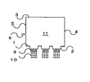
図1は、本発明の液滴製造装置を示す概略断面図であり、気体中に液滴を発生する装置の一例である。本発明の液滴製造装置は、液体導入口6と、液滴対象液を噴出する孔を有するプレートを備えた液滴製造装置において、前記液滴対象液を噴出する孔をノズル2に設け、該ノズル2をプレート1に2以上設置することによってプレート1に孔を備えることを特徴とし、具体的には、該液滴製造装置は、容器5を含んでなり、容器5は、一方にプレート1、ノズル2を、振動隔壁3を備え、該プレート1と振動隔壁3を接続する側壁4、該側壁に取り付けられた液体導入口6とからなる。プレート1、ノズル2、振動隔壁3及び側壁4により形成される空間を室11と称す。
FIG. 1 is a schematic cross-sectional view showing a droplet manufacturing apparatus of the present invention, which is an example of an apparatus for generating droplets in a gas. The droplet manufacturing apparatus of the present invention is a droplet manufacturing apparatus including a
プレート1には、液滴対象液を噴出させるための多数の孔が設けられたノズル2が2以上取り付けられる。商業的生産規模で液滴を製造する装置の場合、全孔数は300個以上が好ましく、例えば、孔径0.17mmのノズルを用いて月産120トン以上の液滴を製造する場合の全孔数は1000個以上である。
Two or
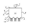
図2は、振動隔壁3の直径と等しい内径の側壁4を有する円筒部と、プレート1の直径と等しい内径の側壁4を有する円筒部を直接接続した構造で、図1の均一液滴製造装置の振動隔壁3に加振機7を接続したものである。より均一粒径の液滴を製造するには、液滴対象液に振動を与えるための振動隔壁3、加振機7を備えてなり、室11の液滴対象液に振動を加えて、孔から出た液滴対象液の噴出流を切断するほうが望ましい。
2 is a structure in which a cylindrical portion having a side wall 4 having an inner diameter equal to the diameter of the
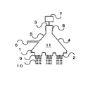
図3は、本発明の均一粒径液滴製造装置の別の一例を示す概略断面図で、気体中に液滴を発生する装置である。振動隔壁3よりも大きな口径を有するプレート1と、該プレート1と振動隔壁3とを接続する側壁4を備えてなる。振動隔壁3をプレート1の口径より小さくすることで、小さな加振機を用いて商業的規模で経済的に有利に液滴を製造できるため好ましい。図3において、本発明の均一粒径液滴製造装置は、振動隔壁3よりプレート1の口径が大きいことから、プレート1と側壁4の間にプレート1と同径の円筒部を設けても良いし、振動隔壁3と側壁4の間に振動隔壁3と同径の円筒部を設けても良い。
FIG. 3 is a schematic cross-sectional view showing another example of the uniform particle size droplet producing apparatus of the present invention, which is an apparatus for generating droplets in a gas. A
加振機7の振動は、振動隔壁3によって均一に室11へ伝播される。振動隔壁3の振動が直接室11の壁へ伝播しないように、好ましくは防振装置8を介して接続される。振動隔壁3は一般に振動板であり、以下振動隔壁3を振動板3で代表させて説明する。
The vibration of the
振動板の振動は振動板3に接続された加振機7によって与えられる。その振動が液体導入口6より導入され室11に充満した液滴対象液中を圧力パルスとして伝播し、液滴対象液の噴出流の液柱9表面に表面波を形成する。一定振動の表面波によって液滴対象液の噴出流が切断され、均一な大きさの液滴10が生成される。
The vibration of the diaphragm is given by a
液滴対象液の噴出流の液柱9に伝播される振動は、室11に設置された圧力センサー(図示せず)で測定される圧力パルスを所定の値になすように調節される。圧力パルスの所定の値は、圧力センサーの出力を加振機7の制御器(図示せず)にフィードバックして加振機の加速度を自動調節するか、手動で圧力センサーの出力が所定の値になるように加振機7の加速度を調節する方法等により設定される。
The vibration propagated to the
液滴の大きさは通常0.05〜5mmの間の均一な液滴径であるので、通常の振動の周波数は約100〜10000Hzを用いることが好ましい。これより小さな液滴の場合には10000Hz以上、またはこれより大きな液滴の場合には100Hz以下の周波数であってよい。 Since the droplet size is usually a uniform droplet diameter between 0.05 and 5 mm, it is preferable to use a frequency of normal vibration of about 100 to 10000 Hz. For smaller droplets, the frequency may be 10000 Hz or more, or for larger droplets, the frequency may be 100 Hz or less.
防振装置8、加振機7、室11の形状についての詳細は特開平5−345125号公報に詳しく記述されている。
Details of the shape of the vibration isolator 8, the
上記装置において、液滴対象液は、液体導入口6を通じ、流量調節装置(図示せず)を経由して所定の流量で室11に導入され、室11内に充満した液滴対象液はプレート1に設置したノズル2の孔から層流状態で液柱9を形成するように噴出され、噴出された液柱9は振動板3から液滴対象液中を伝播してきた振動により液滴10となる。液滴対象液の所定の流量とは、孔から噴出する液滴対象液の液柱が層流状態で噴出する流量であって、液滴対象液の密度ρ、粘度μ、液滴対象液の液柱の直径d(概ね孔の直径に等しい。)と噴出流速uで表される無次元数Re=ρud/μが10から2000になる噴出速度を与える流速である。例えば、孔の孔径がd=0.17mmの場合は噴流速度u=180cm/secが選ばれ、d=0.1mmの場合は噴流速度270cm/secが選ばれる。液滴対象液の流量は、例えば液滴対象液の流量計とフィードバック回路で接続された調節弁又は液滴対象液の供給ポンプの回転数等によって調節される。本発明で使用される液滴対象液は特に限定されず、有機溶剤、水溶液、重合性単量体、微細なエマルジョンやサスペンションも含まれる。中でも重合性単量体やその混合物を用いることが望ましい。この重合性単量体としては公知のものが使用できるが、例えば、スチレン、o−メチルスチレン、m−メチルスチレン、p−メチルスチレン、p−メトキシスチレン、p−フェニルスチレン、p−クロルスチレン、3,4−ジクロルスチレン、エチルスチレン、2,4−ジメチルスチレン、p−n−ブチルスチレン、p−tert−ブチルスチレン、p−n−ヘキシルスチレン、p−n−オクチルスチレン、p−n−ノニルスチレン、p−n−デシルスチレン等のスチレン及びその誘導体類、エチレン、プロピレン、ブチレン、イソブチレン等のエチレン性不飽和モノオレフィン類、ジビニルベンゼン、ジビニルトルエン、ジビニルキシレン、トリビニルベンゼン等のポリビニル芳香族化合物、塩化ビニル、塩化ビニリデン、臭化ブチル、フッ化ビニル等のハロゲン化エステル類、酢酸ビニル、プロピオン酸ビニル、安息香酸ビニル等のカルボン酸のビニルエステル類、メタクリル酸、メタクリル酸メチル、メタクリル酸エチル、メタクリル酸プロピル、メタクリル酸n−ブチル、メタクリル酸n−オクチル、メタクリル酸ドデシル、メタクリル酸ラウリル、メタクリル酸ステアリル、メタクリル酸2−エチルヘキシル、メタクリル酸フェニル、メタクリル酸ジメチルアミノエチル、メタクリル酸ジメチルアミノメチル、メタクリル酸2−ヒドロキシエチル、メタクリル酸2−ヒドロキシプロピル、メタクリル酸グリシジル、メタクリル酸ポリエチレングリコール、ジメタクリル酸エチレングリコール、ジメタクリル酸ジエチレングリコール、ジメタクリル酸ポリエチレングリコール、ジメタクリル酸1,3−ブチレングリコール、ジメタクリル酸グリセロール、トリメタクリル酸トリメチロールプロパン等のメタクリル酸及びその誘導体、アクリル酸、アクリル酸メチル、アクリル酸エチル、アクリル酸プロピル、アクリル酸n−ブチル、アクリル酸イソブチル、アクリル酸n−オクチル、アクリル酸ドデシル、アクリル酸ステアリル、アクリル酸2−エチルヘキシル、アクリル酸クロルエチル、アクリル酸フェニル、アクリル酸メトキシエチル、アクリル酸グリシジル、アクリル酸2−ヒドロキシエチル、アクリル酸2−ヒドロキシプロピル、アクリル酸ポリエチレングリコール、トリアクリル酸ペンタエリスリトール等のアクリル酸及びその誘導体、メタクリル酸アリル、アリルグリシジルエーテル、トリアリルイソシアヌレート、トリアリルシアヌレート等のアリル化合物類、ビニルメチルエーテル、ビニルエチルエーテル、ビニルイソブチルエーテル、ブタンジオールジビニルエーテル、ジエチレングリコールジビニルエーテル等のビニルエーテル類、ビニルメチルケトン、ビニルヘキシルケトン、ビニルイソプロペニルケトン等のビニルケトン類、N−ビニルピロール、N−ビニルカルバゾール、N−ビニルピロリドン等のN−ビニル化合物、ビニルナフタリン類、アクリロニトリル、メタクリルニトリル、アクリルアミド、メタクリルアミド、メチレンビスアクリルアミド、ヒドロキシエチルアクリルアミド、メチロールアクリルアミド等のアクリルアミドもしくはメタクリルアミド類等の重合性単量体が挙げられる。これらは単独あるいは組み合わせて使用することができる。
In the above apparatus, the liquid droplet target liquid is introduced into the
さらに液滴対象液は、重合性単量体と、重合開始剤、非重合性液体、線状ポリマー、固体微粒子等との混合物であっても良い。 Furthermore, the droplet target liquid may be a mixture of a polymerizable monomer and a polymerization initiator, a non-polymerizable liquid, a linear polymer, solid fine particles, and the like.
例えば、重合性単量体を含み、必要に応じて非重合性液体、線状ポリマー、重合開始剤等を含んだ混合物を液滴対象液に使用し、得られた液滴を重合することにより、ポリマービーズを得ることができる。この場合、重合性単量体は架橋ポリマーを生成しうる重合性単量体を少なくとも1つ含むのが望ましく、例えば上記例示のものが使用できる。中でも、スチレン及びその誘導体類、カルボン酸のビニルエステル類について好適に用いることが出来る。非重合性液体としては、特に限定されず、例えばトルエン、キシレン、ベンゼン、ヘプタン、オクタン、ヘキサン、シクロヘキサン、酢酸エチル、酢酸ブチル、アルコール類、アセトン、水等を目的に応じて単独あるいは組み合わせて使用することができる。線状ポリマーについても特に制約はないが、例えば上記例示の重合性単量体単位を含む線状ポリマーがあげられる。なお、液滴対象液に固体微粒子が含まれる場合は、固体微粒子の粒子径は分散相が噴出させられる孔より小さいことが好ましい。 For example, by using a mixture containing a polymerizable monomer and, if necessary, a non-polymerizable liquid, a linear polymer, a polymerization initiator, etc., as a droplet target liquid, and polymerizing the obtained droplets , Polymer beads can be obtained. In this case, the polymerizable monomer desirably contains at least one polymerizable monomer capable of forming a crosslinked polymer, and for example, those exemplified above can be used. Of these, styrene and its derivatives, and vinyl esters of carboxylic acid can be preferably used. The non-polymerizable liquid is not particularly limited, and for example, toluene, xylene, benzene, heptane, octane, hexane, cyclohexane, ethyl acetate, butyl acetate, alcohols, acetone, water, etc. are used alone or in combination depending on the purpose. can do. Although there is no restriction | limiting in particular also about a linear polymer, For example, the linear polymer containing the polymerizable monomer unit of the said illustration is mention | raise | lifted. In the case where the droplet target liquid contains solid fine particles, the particle size of the solid fine particles is preferably smaller than the holes through which the dispersed phase is ejected.
重合開始剤には公知のものを使用でき、また使用される重合性単量体に応じて選ぶことが好ましい。例えば、ラウロイルパーオキサイド、過酸化ベンゾイル、t−ブチルパーオキシベンゾエート、イソブチル−t−ブチルパーオキシカーボネート、過安息香酸ブチル、1,1−ビス(t−ブチルパーオキシ)3,3,5−トリメチルシクロヘキサンのような有機過酸化物や、アゾビスイソブチロニトリル、アゾビスジメチルバレロニトリル、アゾビストリメチルペンタン、アゾビスシアノバレリアン酸などのアゾ化合物、過硫酸塩、過酸化水素、又はハイドロパーオキサイド等の水溶性ラジカル重合開始剤が使用でき、またこれらを併用しても何ら差し支えない。なお、重合開始剤は、液滴対象液に直接混合しても良い。 A well-known thing can be used for a polymerization initiator, It is preferable to select according to the polymerizable monomer used. For example, lauroyl peroxide, benzoyl peroxide, t-butyl peroxybenzoate, isobutyl-t-butyl peroxycarbonate, butyl perbenzoate, 1,1-bis (t-butylperoxy) 3,3,5-trimethyl Organic peroxides such as cyclohexane, azo compounds such as azobisisobutyronitrile, azobisdimethylvaleronitrile, azobistrimethylpentane, azobiscyanovaleric acid, persulfates, hydrogen peroxide, or hydroperoxide Water-soluble radical polymerization initiators such as these can be used, and they can be used in combination. The polymerization initiator may be directly mixed with the liquid to be dropped.
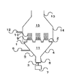
図4は、本発明装置の更に別の実施例を示す概略断面図で互いに難溶性の2液体を用い、一方の液体中に他方の液体の液滴を形成させ、液滴スラリーを形成する装置である。この装置は、図3に示した装置のプレート1の面に液滴供給口12とスラリー排出口13を有する円錐台状の容器14を付設した構造からなり、お互いに難溶性の液体を用いて一方の液体(この場合は、他方より比重が等しいか又は大きい。)中に他方の液体(この場合は、他方より比重が等しいか又は小さい。)の液滴を形成する装置である。上記装置においては、液体供給口12から供給され、容器14内のスラリー室15に充満する液体中に、上記した操作により、スラリー室15に充満している液体に対して難溶性の液滴対象液を液体導入口6より導入して液滴を製造し、液滴を含むスラリーを排出口13より回収する。
FIG. 4 is a schematic cross-sectional view showing still another embodiment of the apparatus of the present invention, which uses two liquids that are sparingly soluble with each other, forms droplets of the other liquid in one liquid, and forms a droplet slurry. It is. This apparatus has a structure in which a
スラリー室15に充満させる液体(連続相)としては、液滴対象液(分散相)に対して難溶性であれば特に限定はなく、連続相に用いる溶媒は特に限定されないが、例えば水や水溶液が経済的で環境負荷が小さく好ましい。また連続相には分散剤や塩類を含有させてもよい。分散剤は、懸濁重合で一般に使用されるものを用いることができ、例えば、ゼラチン、ポリビニルアルコール、ポリビニルピロリドン、ポリアクリルアミド、デンプン等の高分子分散剤、燐酸カルシウム、ハイドロキシアパタイト、ピロリン酸マグネシウム等の連続相に難溶な無機塩、カルボキシメチルセルロース、ヒドロキシエチルセルロース等のセルロースエーテル類を用いることができる。また、分散剤として連続相に難溶な無機塩を用いる場合には、α−オレフィンスルホン酸ソーダ、ドデシルベンゼンスルホン酸ソーダ等のアニオン界面活性剤を併用するのが好ましい。
The liquid (continuous phase) to be filled in the
以下、プレート1とノズル2について記述する。プレート1の形状は角形、円形等、任意の形状であってよく、プレート1に設置するノズル2の配置も任意の位置に設置してよい。商業生産規模で均一粒径の液滴を製造するためのプレート1の大きさは約200〜約3000mmの大きさが望ましい。これ以上大きくなると、ノズル設置作業等のメインテナンス負荷が大きく、時間もかかる上、経済性において極めて不利であることが多い。これ以下の大きさでは、商業的生産規模とは考えにくい上、プレート本体に直接、孔をあけ、隣接する孔から噴出する液体の相互作用により、液滴の均一性が乱されないような数と配列にする従来の方法に比べ、本発明を実施する効果は小さい。プレート下面(ノズル設置面との反対側)に平面部を作ると、気泡が付着し、圧力伝播を阻害し、均一粒径の液滴が生成できにくくする恐れがある。従って、プレート1に設けるノズル穴の周囲はテーパーとし、平面部を作らないように加工することが望ましい。さらに、その上に気泡の付着を防止ためのコーティングをすることが望ましい。
Hereinafter, the
図4の構造を持つ液滴製造装置の場合、液体供給口12から供給される容器14内のスラリー室15に充満する液体(分散剤)がプレート中心部まで均一にいきわたるためには容器14は円筒形、プレート1は円形板が望ましく、ノズルは中心円周上で一定間隔に配置することが望ましい。プレートに配置するノズル配列は何列あっても良い。
In the case of the droplet manufacturing apparatus having the structure of FIG. 4, in order for the liquid (dispersant) filling the
ノズル2を取り付ける位置にはノズル2の大きさに合った貫通穴(以下、ノズル穴と記す。)が必要な数だけあけられている。多数のノズル穴を持つプレートを使用して、その数より少ないノズル数で液滴を製造する場合は、ノズルを設置しないノズル穴には閉止板を取り付ける。それによって必要な生産量の液滴の製造が可能になる。また、振動の圧力パルスが弱く、均一粒径の液滴が得られにくい位置は、閉止板にするか、あらかじめその位置を除外してノズル穴をあけて使用する。
A necessary number of through holes (hereinafter referred to as nozzle holes) matching the size of the
ノズル2、閉止板をプレートに設置する場合、ボルト締め付けによってプレート1とOリングを挟み込んで固定され、内部の液体が漏れないようにシールされる。ノズル2には2個以上の孔が設けられ、隣接する孔から噴出する液体の相互作用により、液滴の均一性が乱されないような数と配列になっている。
When the
ノズル2の形状は円形や角型などの任意形状の平板、円形や角型部を凸型にしてその周囲にフランジを付けた形状等、どんな形状でも良い。ノズルは孔詰まりを取り除くための洗浄、孔修理をするためには概ね10mm以上300mm以下の径を有することが、取り扱い易く、望ましい大きさであり、更には30〜100mmが好ましい。ノズルに付与する孔の数は特に限定はなく、所望とする生産規模に応じて適宜選択することが出来るが、1つのノズルには、ノズルの大きさにもよるが、概ね2以上1000以下の孔を有していることが好ましく、更に好ましくは、30以上300以下であることが好ましい。
The shape of the
本発明の液滴製造装置を用いて製造した液滴は、粒子径が均一であることが好ましい。その均一性は、好ましくは80%以上であり、より好ましくは85%以上であり、最も好ましくは95%以上である。ここで本発明における均一性とは、得られた液滴を実体顕微鏡で拡大撮影し、少なくとも100個以上の液滴を画像処理して液滴径を測定し、目標の粒子径の±5μmの粒径範囲内に含まれる液滴の重量%で表した値である。 The droplets manufactured using the droplet manufacturing apparatus of the present invention preferably have a uniform particle size. The uniformity is preferably 80% or more, more preferably 85% or more, and most preferably 95% or more. Here, the uniformity in the present invention means that the obtained droplet is magnified and photographed with a stereomicroscope, and at least 100 droplets are image-processed to measure the droplet diameter, and the target particle diameter is ± 5 μm. It is a value expressed by weight% of droplets included in the particle size range.
また、重合性単量体を含んでなる本発明の液滴から得られたポリマービーズもまた良好な均一性を有するものである。 The polymer beads obtained from the droplets of the present invention comprising a polymerizable monomer also have good uniformity.
次に、実施例に基づいて本発明を更に詳細に説明するが、本発明はこれら実施例に限定されるものではない。各例における液滴の均一性は、回収したスラリーを密閉ガラスセルにサンプリングし、実体顕微鏡で拡大撮影し、画像処理して液滴径を測定した。測定個数は測定精度を上げるため多数測定する方が望ましい。その液滴を重量換算して目標粒径の±5μm範囲内に含まれる液滴の重量%で評価した。目標の均一性は98%以上と設定した。
(実施例1)
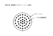
内径950mm、高さ2160mmのスラリー室15に設置して図4と同様の商業規模で2種類の液体よりなる液滴スラリー製造装置を用いた。プレートは径509mmのものを使用した。ノズルを設置する場所に内径40mmのノズル穴を持っている。本実施例では37個のノズルを取り付ける構造となっている。ノズルはプレートとOリングでシールし、ボルトで4点締めして取り付ける構造となっている。ノズルは外形70mm(フランジ部幅15mmを含む)、径36mm内に孔を開けることができる。ノズルは内径0.17mmの孔を45個有し、隣同士の孔の距離は4mmとし、孔から噴出する液体の相互作用によって液滴の均一性が乱れないように配列した。このノズルをプレートに37個設置して使用した。全孔数は1665個である。37個のノズル配置は、図5に示すように、プレートの中心に1個、中心から半径78mmの同心円状に6個、半径156mm円状に12個、半径234mm円状に18個を配置した。ノズルは同心円上で均等距離に配置されている。
EXAMPLES Next, although this invention is demonstrated further in detail based on an Example, this invention is not limited to these Examples. The uniformity of the droplets in each example was measured by sampling the recovered slurry in a sealed glass cell, enlarging and photographing with a stereomicroscope, image processing, and measuring the droplet diameter. It is desirable to measure a large number of measurements in order to increase measurement accuracy. The droplets were converted to weight and evaluated by the weight% of the droplets included in the target particle size within ± 5 μm. The target uniformity was set at 98% or more.
(Example 1)
A droplet slurry production apparatus comprising two kinds of liquids on a commercial scale similar to that shown in FIG. 4 was used in the
スラリー室に196リットル/時のPVA水溶液(PVA濃度は320ppmの希薄なもの)を供給しておき、液体導入口から246リットル/時のスチレンを供給し、加振機で800Hzの振動を与えてO/W型の水溶液/スチレン液滴スラリーを製造した。必要な強さの加振を与えることにより、98%以上の割合で粒子径450μmの均一なスチレン液滴を得た。
(実施例2)
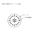
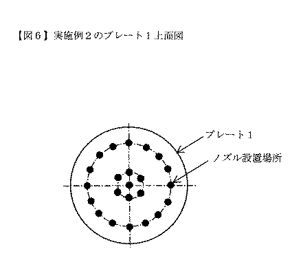
プレートは23個のノズルを取り付ける構造とした以外は、実施例1と同様な商業規模の2種類の液体よりなる液滴スラリー製造装置を用いてスチレン液滴スラリーを製造した。ノズルは、内径0.10mmの孔を148個有し、隣同士の孔の距離は2mmとし、孔から噴出する液体の相互作用によって液滴の均一性が乱れないように配列した。このノズルをプレートに23個設置して使用した。全孔数は3404個である。23個のノズル配置は、図6に示すように、プレートの中心に1個、中心から半径78mmの同心円状に6個、半径210mm円状に16個を配置した。ノズルは同心円上で均等距離に配置されている。スラリー室に206リットル/時のPVA水溶液(PVA濃度は320ppmの希薄なもの)を供給しておき、液体導入口から257リットル/時のスチレンを供給し、加振機で1990Hzの振動を与えてO/W型の水溶液/スチレン液滴スラリーを製造した。必要な強さの加振を与えることにより、98%以上の割合で粒子径270μmの均一なスチレン液滴を得た。
(実施例3)
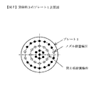
実施例1と同様な商業規模の2種類の液体よりなる液滴スラリー製造装置を用いた。使用したプレート、ノズルは実施例1と同様なものを用いた。プレートには37個のノズルを取り付けることができる。ノズルは内径0.10mmの孔を148個有し、隣同士の孔の距離は2mmとし、孔から噴出する液体の相互作用によって液滴の均一性が乱れないように配列した。このノズルをプレートに22個設置して使用した。残りの15個は閉止板を取り付けた。全孔数は3256個である。22個のノズル配置は、図7に示すように、プレートの中心に1個、中心から半径78mmの同心円状に6個、半径234mm円状に15個を取り付けた。半径156mm円状に12個、半径234mm円状に3個、計15個の閉止板を取り付けた。スラリー室に197リットル/時のPVA水溶液(PVA濃度は320ppmの希薄なもの)を供給しておき、液体導入口から246リットル/時のスチレンを供給し、加振機で1900Hzの振動を与えてO/W型の水溶液/スチレン液滴スラリーを製造した。必要な強さの加振を与えることにより、98%以上の割合で粒子径270μmの均一なスチレン液滴を得た。
(比較例1)
実施例1と同様な商業規模の2種類の液体よりなる液滴スラリー製造装置を用いた。本比較例ではノズルを使用せず、プレートに直接孔をあけて用いた。本比較例で使用したプレートは内径0.10mmの孔を3367個有する。隣同士の孔の間隔は実施例2と同じ2mmとした。スラリー室に204リットル/時のPVA水溶液(PVA濃度は320ppmの希薄なもの)を供給しておき、液体導入口から254リットル/時のスチレンを供給し、加振機で1990Hzの振動を与えてO/W型の水溶液/スチレン液滴スラリーを製造した。必要な強さの加振を与えたが、粒子径270μmの均一なスチレン液滴は65%の割合であった。
196 liters / hour of PVA aqueous solution (PVA concentration is 320 ppm dilute) is supplied to the slurry chamber, 246 liters / hour of styrene is supplied from the liquid inlet, and vibration of 800 Hz is applied by a vibrator. An O / W type aqueous solution / styrene droplet slurry was prepared. By applying the required intensity of vibration, uniform styrene droplets having a particle diameter of 450 μm were obtained at a ratio of 98% or more.
(Example 2)
A styrene droplet slurry was produced using a droplet slurry production apparatus composed of two types of liquids on a commercial scale similar to Example 1, except that the plate was configured to mount 23 nozzles. The nozzle had 148 holes with an inner diameter of 0.10 mm, the distance between adjacent holes was 2 mm, and was arranged so that the uniformity of the droplets was not disturbed by the interaction of the liquid ejected from the holes. 23 nozzles were installed on the plate and used. The total number of holes is 3404. As shown in FIG. 6, the nozzle arrangement of 23 nozzles was 1 at the center of the plate, 6 concentrically with a radius of 78 mm from the center, and 16 with a radius of 210 mm. The nozzles are arranged at equal distances on a concentric circle. Supply 206 liters / hour of PVA aqueous solution (a dilute PVA concentration of 320 ppm) to the slurry chamber, supply 257 liters / hour of styrene from the liquid inlet, and give vibration of 1990 Hz with a vibrator. An O / W type aqueous solution / styrene droplet slurry was prepared. By applying the required strength, uniform styrene droplets having a particle size of 270 μm were obtained at a ratio of 98% or more.
(Example 3)
The same droplet slurry production apparatus consisting of two kinds of liquids on a commercial scale as in Example 1 was used. The same plate and nozzle as used in Example 1 were used. 37 nozzles can be attached to the plate. The nozzle had 148 holes with an inner diameter of 0.10 mm, the distance between adjacent holes was 2 mm, and was arranged so that the uniformity of the droplets was not disturbed by the interaction of the liquid ejected from the holes. Twenty-two nozzles were installed on the plate for use. The remaining 15 were fitted with closing plates. The total number of holes is 3256. As shown in FIG. 7, the 22 nozzles were arranged in such a manner that one at the center of the plate, six in a concentric circle with a radius of 78 mm from the center, and 15 in a circle with a radius of 234 mm. A total of 15 closing plates, 12 in a circular shape with a radius of 156 mm and 3 in a circular shape with a radius of 234 mm, were attached. A 197 liter / hour PVA aqueous solution (a dilute PVA concentration of 320 ppm) was supplied to the slurry chamber, 246 liter / hour styrene was supplied from the liquid inlet, and a vibration of 1900 Hz was applied by a vibrator. An O / W type aqueous solution / styrene droplet slurry was prepared. By applying the required strength, uniform styrene droplets having a particle size of 270 μm were obtained at a ratio of 98% or more.
(Comparative Example 1)
The same droplet slurry production apparatus consisting of two kinds of liquids on a commercial scale as in Example 1 was used. In this comparative example, a nozzle was not used, but a hole was directly made in the plate. The plate used in this comparative example has 3367 holes with an inner diameter of 0.10 mm. The distance between adjacent holes was 2 mm, the same as in Example 2. 204 L / hr of PVA aqueous solution (PVA concentration is 320 ppm dilute) is supplied to the slurry chamber, 254 L / hr of styrene is supplied from the liquid inlet, and vibration of 1990 Hz is applied by a vibrator. An O / W type aqueous solution / styrene droplet slurry was prepared. Although the required strength was applied, uniform styrene droplets with a particle size of 270 μm accounted for 65%.
1 プレート
2 ノズル
3 振動隔壁
4 側壁
5 容器
6 液体導入口
7 加振機
8 防振装置
9 液柱
10 液滴
11 室
12 液体供給口
13 スラリー排出口
14 容器
15 スラリー室
DESCRIPTION OF
Claims (5)
Priority Applications (1)
| Application Number | Priority Date | Filing Date | Title |
|---|---|---|---|
| JP2004118052A JP4706181B2 (en) | 2004-04-13 | 2004-04-13 | Droplet production equipment |
Applications Claiming Priority (1)
| Application Number | Priority Date | Filing Date | Title |
|---|---|---|---|
| JP2004118052A JP4706181B2 (en) | 2004-04-13 | 2004-04-13 | Droplet production equipment |
Publications (2)
| Publication Number | Publication Date |
|---|---|
| JP2005296845A true JP2005296845A (en) | 2005-10-27 |
| JP4706181B2 JP4706181B2 (en) | 2011-06-22 |
Family
ID=35329038
Family Applications (1)
| Application Number | Title | Priority Date | Filing Date |
|---|---|---|---|
| JP2004118052A Expired - Fee Related JP4706181B2 (en) | 2004-04-13 | 2004-04-13 | Droplet production equipment |
Country Status (1)
| Country | Link |
|---|---|
| JP (1) | JP4706181B2 (en) |
Cited By (1)
| Publication number | Priority date | Publication date | Assignee | Title |
|---|---|---|---|---|
| WO2010058661A1 (en) * | 2008-11-20 | 2010-05-27 | フロイント産業株式会社 | Seamless capsule-manufacturing device |
Citations (10)
| Publication number | Priority date | Publication date | Assignee | Title |
|---|---|---|---|---|
| JPS5649154A (en) * | 1979-09-26 | 1981-05-02 | Morishita Jintan Co | Manufacture of capsule that can continuously masssproduce ultramicroocapsule and its manufacturing device |
| JPS5822062A (en) * | 1981-08-03 | 1983-02-09 | 森下仁丹株式会社 | Method and apparatus for producing microcapsule filled with high melting substance |
| JPH03249931A (en) * | 1989-11-16 | 1991-11-07 | Mitsubishi Kasei Corp | Production of oil-in-water type uniform droplets dispersion and method for polymerizing uniform-diameter-polymer beads |
| JPH0411937A (en) * | 1990-04-27 | 1992-01-16 | Mitsui Toatsu Chem Inc | Nozzle disk for granulation tower |
| JPH05345125A (en) * | 1992-06-12 | 1993-12-27 | Kanegafuchi Chem Ind Co Ltd | Uniform particle size droplet manufacturing equipment |
| JPH06134276A (en) * | 1992-10-27 | 1994-05-17 | Chiyoda Corp | Dripping nozzle for countercurrent granulation equipment |
| JP2001149765A (en) * | 1999-12-01 | 2001-06-05 | Kao Corp | Droplet generator |
| JP2002534402A (en) * | 1999-01-07 | 2002-10-15 | バイエル アクチェンゲゼルシャフト | Method and apparatus for producing bisphenol A prill, and bisphenol A prill produced according to the method and apparatus |
| JP2002536154A (en) * | 1999-02-04 | 2002-10-29 | バイエル アクチェンゲゼルシャフト | Die plate exchange apparatus for injection granulation tower and automated exchange method |
| JP2003190258A (en) * | 2001-12-28 | 2003-07-08 | Kao Corp | Forming component liquid curing device |
-
2004
- 2004-04-13 JP JP2004118052A patent/JP4706181B2/en not_active Expired - Fee Related
Patent Citations (10)
| Publication number | Priority date | Publication date | Assignee | Title |
|---|---|---|---|---|
| JPS5649154A (en) * | 1979-09-26 | 1981-05-02 | Morishita Jintan Co | Manufacture of capsule that can continuously masssproduce ultramicroocapsule and its manufacturing device |
| JPS5822062A (en) * | 1981-08-03 | 1983-02-09 | 森下仁丹株式会社 | Method and apparatus for producing microcapsule filled with high melting substance |
| JPH03249931A (en) * | 1989-11-16 | 1991-11-07 | Mitsubishi Kasei Corp | Production of oil-in-water type uniform droplets dispersion and method for polymerizing uniform-diameter-polymer beads |
| JPH0411937A (en) * | 1990-04-27 | 1992-01-16 | Mitsui Toatsu Chem Inc | Nozzle disk for granulation tower |
| JPH05345125A (en) * | 1992-06-12 | 1993-12-27 | Kanegafuchi Chem Ind Co Ltd | Uniform particle size droplet manufacturing equipment |
| JPH06134276A (en) * | 1992-10-27 | 1994-05-17 | Chiyoda Corp | Dripping nozzle for countercurrent granulation equipment |
| JP2002534402A (en) * | 1999-01-07 | 2002-10-15 | バイエル アクチェンゲゼルシャフト | Method and apparatus for producing bisphenol A prill, and bisphenol A prill produced according to the method and apparatus |
| JP2002536154A (en) * | 1999-02-04 | 2002-10-29 | バイエル アクチェンゲゼルシャフト | Die plate exchange apparatus for injection granulation tower and automated exchange method |
| JP2001149765A (en) * | 1999-12-01 | 2001-06-05 | Kao Corp | Droplet generator |
| JP2003190258A (en) * | 2001-12-28 | 2003-07-08 | Kao Corp | Forming component liquid curing device |
Cited By (3)
| Publication number | Priority date | Publication date | Assignee | Title |
|---|---|---|---|---|
| WO2010058661A1 (en) * | 2008-11-20 | 2010-05-27 | フロイント産業株式会社 | Seamless capsule-manufacturing device |
| JP2010119356A (en) * | 2008-11-20 | 2010-06-03 | Freunt Ind Co Ltd | Seamless capsule production system |
| US8992196B2 (en) | 2008-11-20 | 2015-03-31 | Freund Corporation | Seamless capsule manufacturing apparatus |
Also Published As
| Publication number | Publication date |
|---|---|
| JP4706181B2 (en) | 2011-06-22 |
Similar Documents
| Publication | Publication Date | Title |
|---|---|---|
| JP5346109B2 (en) | Equipment for sonicating liquids | |
| EP0051210B2 (en) | Process for preparing uniform size spheroidal polymer beads | |
| EP0173518B1 (en) | Process for preparing uniformly sized polymer particles | |
| JP5987218B2 (en) | Method for producing uniform polymer beads of various sizes | |
| EP4234588A2 (en) | Method of producing uniform, fine polymer beads by vibration jetting | |
| US9095832B2 (en) | Method and apparatus for preparing polymer beads of uniform particle size by suspension polymerisation | |
| EP2938427B1 (en) | Swept membrane emulsification | |
| JP4706181B2 (en) | Droplet production equipment | |
| JP2006117871A (en) | Apparatus for producing droplet | |
| WO2009044926A1 (en) | Method and apparatus for regulating particle diameter and particle diameter distribution of emulsified particles in emulsion | |
| JP2007044654A (en) | Apparatus for preparing liquid droplet | |
| JP2004250630A (en) | Method for producing hydrophobic droplet, method and apparatus for producing polymer beads, and method for producing ion exchange resin | |
| JP4070717B2 (en) | Method for producing resin fine particles | |
| CN101027123A (en) | An angular flow distribution bottom head | |
| JP2005296883A (en) | Droplet production apparatus | |
| JP2001162147A (en) | Uniform droplet generator | |
| JP3529685B2 (en) | Droplet generator | |
| JP3712744B2 (en) | Uniform particle size droplet production equipment | |
| JP3467220B2 (en) | Droplet generator | |
| JP2008095115A (en) | Manufacturing method of resin fine particles, resin fine particles and resin fine particle manufacturing apparatus | |
| JPH06145207A (en) | Production of singly dispersed polymer beads | |
| US9674616B1 (en) | Dynamic acoustic impedance matching device and method | |
| JP2010195863A (en) | Continuous polymerization apparatus for monomer droplet, continuous manufacturing apparatus of polymer particle and continuous polymerization method of monomer droplet | |
| KR20190012014A (en) | Distribution plate |
Legal Events
| Date | Code | Title | Description |
|---|---|---|---|
| A621 | Written request for application examination |
Free format text: JAPANESE INTERMEDIATE CODE: A621 Effective date: 20070226 |
|
| A977 | Report on retrieval |
Free format text: JAPANESE INTERMEDIATE CODE: A971007 Effective date: 20091022 |
|
| A131 | Notification of reasons for refusal |
Free format text: JAPANESE INTERMEDIATE CODE: A131 Effective date: 20091104 |
|
| RD03 | Notification of appointment of power of attorney |
Free format text: JAPANESE INTERMEDIATE CODE: A7423 Effective date: 20091119 |
|
| A521 | Request for written amendment filed |
Free format text: JAPANESE INTERMEDIATE CODE: A523 Effective date: 20091224 |
|
| A131 | Notification of reasons for refusal |
Free format text: JAPANESE INTERMEDIATE CODE: A131 Effective date: 20100413 |
|
| A521 | Request for written amendment filed |
Free format text: JAPANESE INTERMEDIATE CODE: A523 Effective date: 20100607 |
|
| A131 | Notification of reasons for refusal |
Free format text: JAPANESE INTERMEDIATE CODE: A131 Effective date: 20100629 |
|
| A521 | Request for written amendment filed |
Free format text: JAPANESE INTERMEDIATE CODE: A523 Effective date: 20100823 |
|
| A02 | Decision of refusal |
Free format text: JAPANESE INTERMEDIATE CODE: A02 Effective date: 20100914 |
|
| A521 | Request for written amendment filed |
Free format text: JAPANESE INTERMEDIATE CODE: A523 Effective date: 20101209 |
|
| A911 | Transfer to examiner for re-examination before appeal (zenchi) |
Free format text: JAPANESE INTERMEDIATE CODE: A911 Effective date: 20101216 |
|
| TRDD | Decision of grant or rejection written | ||
| A01 | Written decision to grant a patent or to grant a registration (utility model) |
Free format text: JAPANESE INTERMEDIATE CODE: A01 Effective date: 20110215 |
|
| A61 | First payment of annual fees (during grant procedure) |
Free format text: JAPANESE INTERMEDIATE CODE: A61 Effective date: 20110228 |
|
| R150 | Certificate of patent or registration of utility model |
Ref document number: 4706181 Country of ref document: JP Free format text: JAPANESE INTERMEDIATE CODE: R150 |
|
| S531 | Written request for registration of change of domicile |
Free format text: JAPANESE INTERMEDIATE CODE: R313531 |
|
| FPAY | Renewal fee payment (event date is renewal date of database) |
Free format text: PAYMENT UNTIL: 20140325 Year of fee payment: 3 |
|
| R350 | Written notification of registration of transfer |
Free format text: JAPANESE INTERMEDIATE CODE: R350 |
|
| R250 | Receipt of annual fees |
Free format text: JAPANESE INTERMEDIATE CODE: R250 |
|
| R250 | Receipt of annual fees |
Free format text: JAPANESE INTERMEDIATE CODE: R250 |
|
| R250 | Receipt of annual fees |
Free format text: JAPANESE INTERMEDIATE CODE: R250 |
|
| R250 | Receipt of annual fees |
Free format text: JAPANESE INTERMEDIATE CODE: R250 |
|
| R250 | Receipt of annual fees |
Free format text: JAPANESE INTERMEDIATE CODE: R250 |
|
| R250 | Receipt of annual fees |
Free format text: JAPANESE INTERMEDIATE CODE: R250 |
|
| R250 | Receipt of annual fees |
Free format text: JAPANESE INTERMEDIATE CODE: R250 |
|
| R250 | Receipt of annual fees |
Free format text: JAPANESE INTERMEDIATE CODE: R250 |
|
| R250 | Receipt of annual fees |
Free format text: JAPANESE INTERMEDIATE CODE: R250 |
|
| LAPS | Cancellation because of no payment of annual fees |